PSK Modulations
This article focus on Phase Shift Keying (PSK), which belongs to a digital modulation scheme available to transmit digital data.
Note: The article combines mathematical expressions with visuals with the goal to help understanding the concepts from different perspectives. The goal by presenting math equations is not to overwhelm the reader but rather an attempt to connect the theory with the practical world.
PSK Modulation
In the "Phase Modulation (PM)" section we focused mainly on analog information signal being modulated on the carrier angle. We saw that analog angle modulation is not that useful and digital angle modulation is more promising to use.
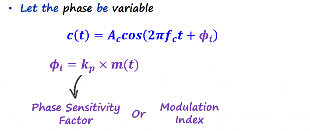
For PSK modulations schemes, the phase is divided in a finite number of phases where each phase is assigned a unique pattern of binary digits. We are no longer affecting the information signal directly to the carrier but we perform an intermediate step of converting the digital information into a phase (through what I am going to call in this article mapping rules). Usually, each phase encodes an equal number of bits. "IQ sampling" and "IQ Plots/Constellations" are key to understand PSK modulation schemes, if this is new to you, go ahead and review those concepts before keep reading.
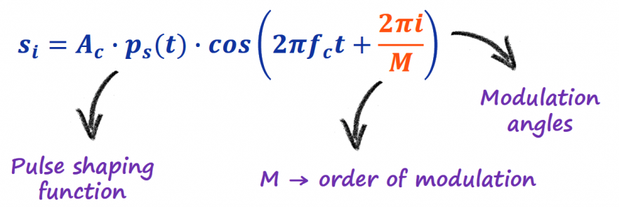
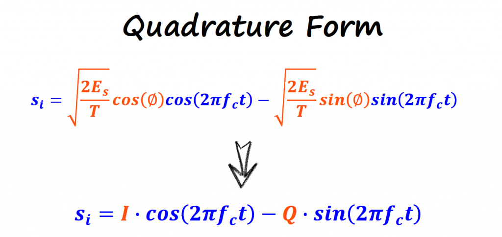
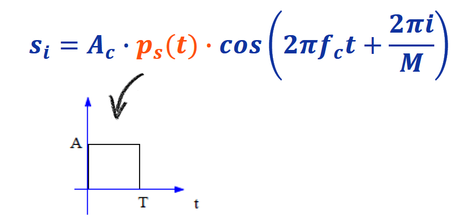
The equation that normally represents the majority of PSK schemes is below.
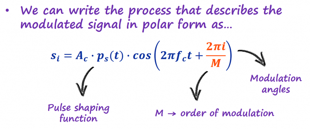
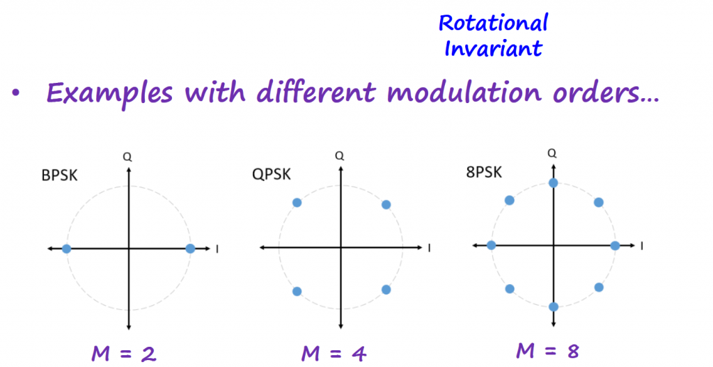
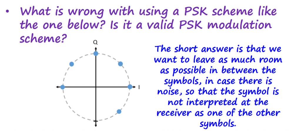
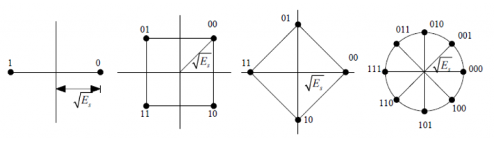
This equation contains a lot of hidden steps that we will go over with some detail in the "Connection Between PSK and IQ Channels" section below. For now, the idea is to see that for different M (order of modulation) I can divide the complex plane into different constellations. All the points in the complex plane have the same amplitude (or distance to the origin).
Connection Between PSK and IQ Channels
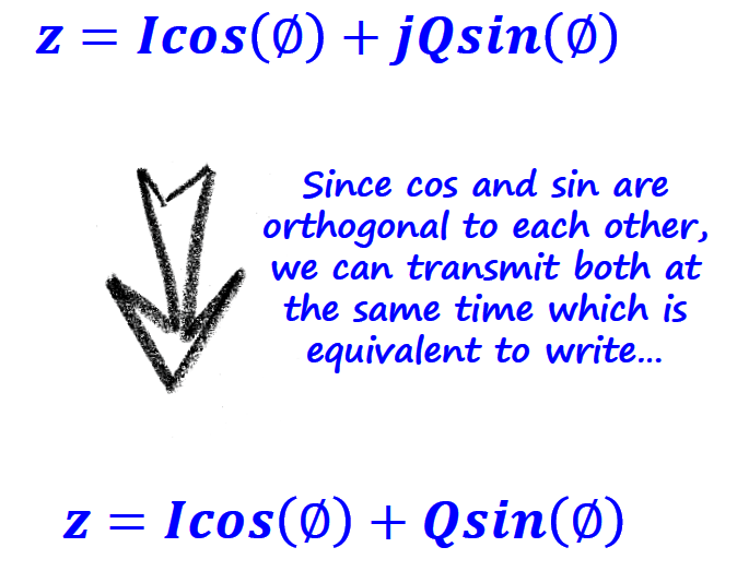
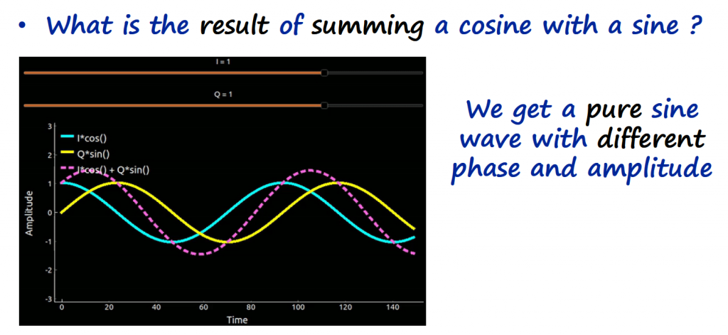
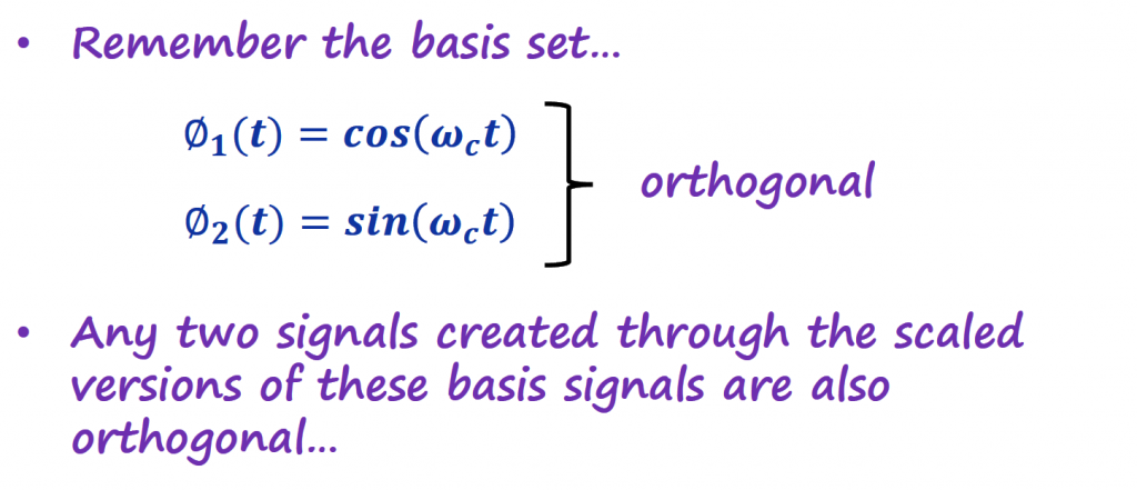
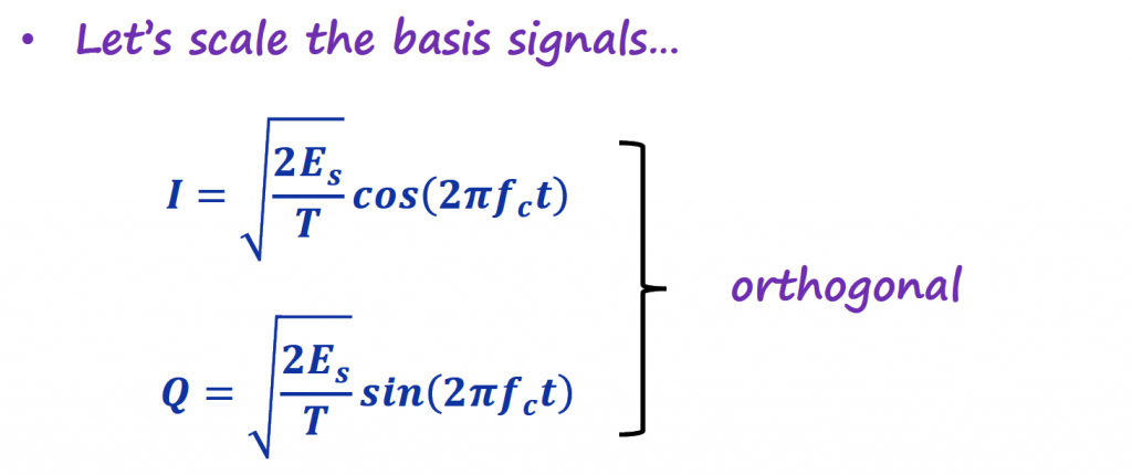
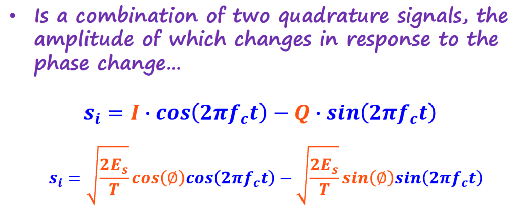
From the "IQ Sampling" section, we covered that we can use this IQ channel concept to create and control a single sinusoidal function. This control is done by simply changing the magnitudes of I and Q, which in turn control the amplitudes of two signals that are orthogonal to each other.
I know IQ channels can be confusing, but spend some time grasping this concept because SDRs rely heavily on this.
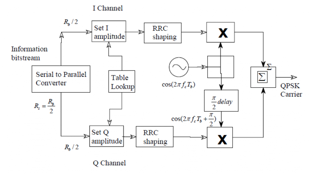
The block diagram below shows the physical implementation of the IQ channels (we will call it in this article IQ Modulator). Notice on how I and Q are modulated into the carrier, and added together to form a single sinusoidal function. That sinusoid will be transmitted by the SDR.
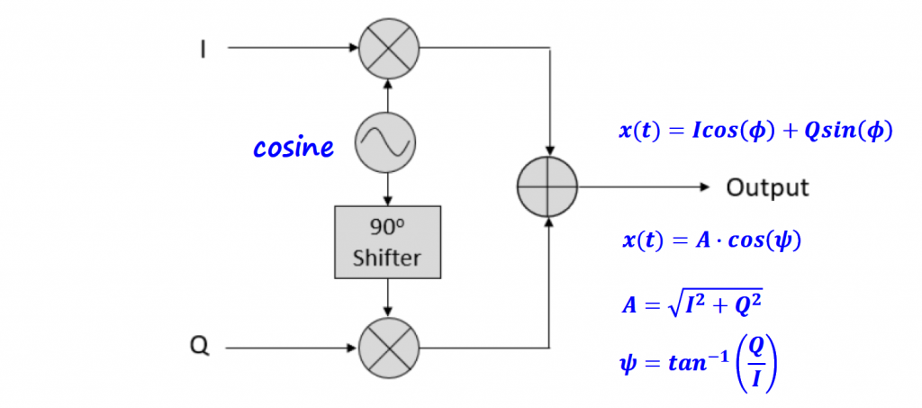
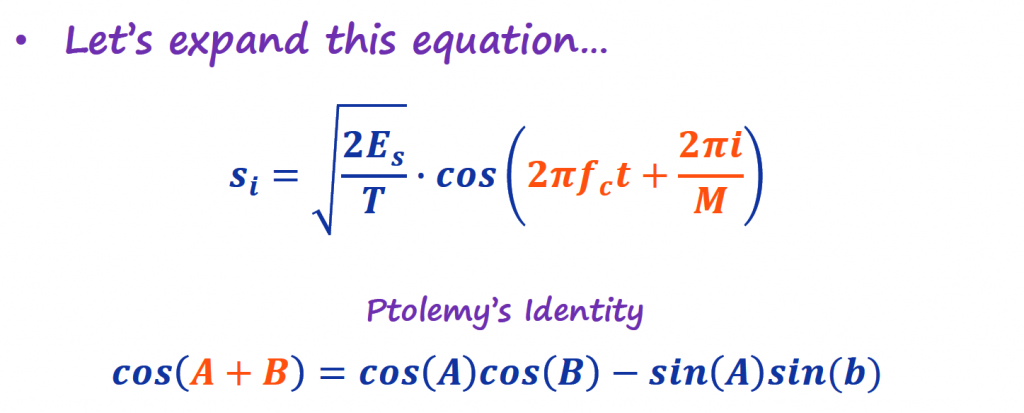
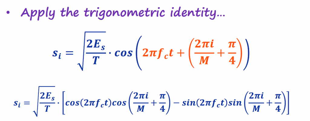
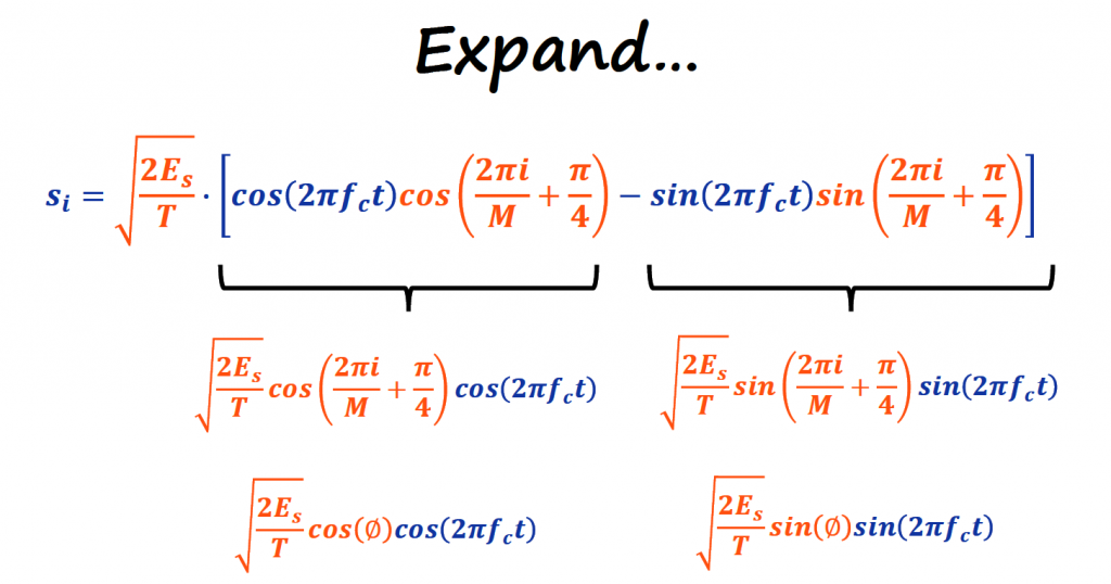
The PSK equation from the previous section is the result coming out of the IQ Modulator. Let's expand it and see how the IQ channel are related with the carrier.
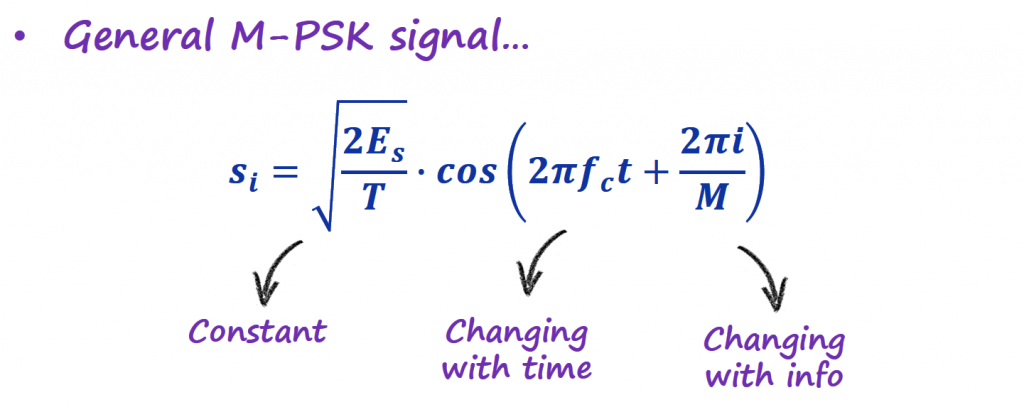
For now, let's assume that Ac · ps(t) = √(2Es/T). We will explain how we get to this value in the "Shaping the Pulse to Reduce Bandwidth" section below.
From now on, all PSK modulation schemes in this article will start from this point. They will mention only how to map symbols to IQ values, and there is no need to include how the modulation to the carrier is done. The modulation with the carrier can be included later using a Product Modulator for example (described in the "Baseband and Passband Signals" from the AM Modulation section).
BPSK
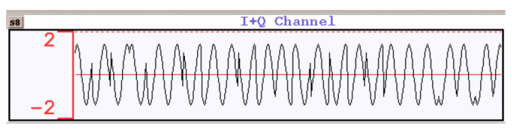
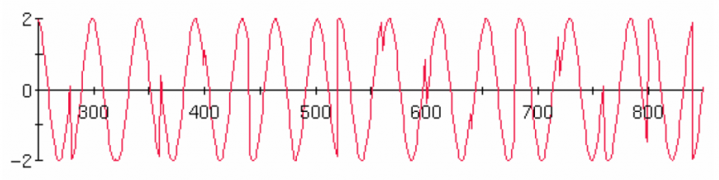
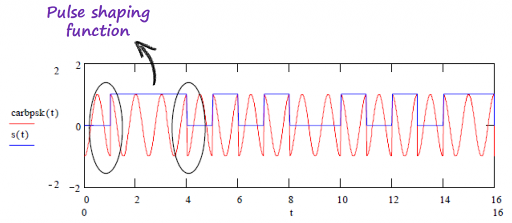
The simplest form of PSK is the Binary PSK (BPSK). Below you have an example of a BPSK modulated signal in time.
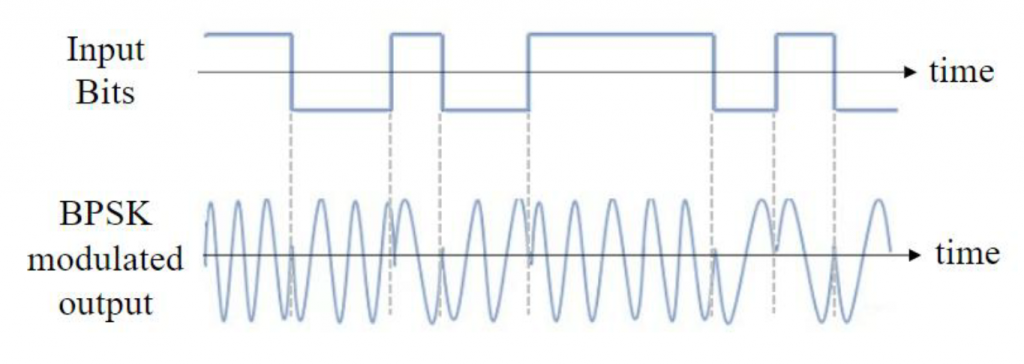
It is hard to understand what is going on in time, so let's move on to the complex plane, using IQ plots (or constellations).
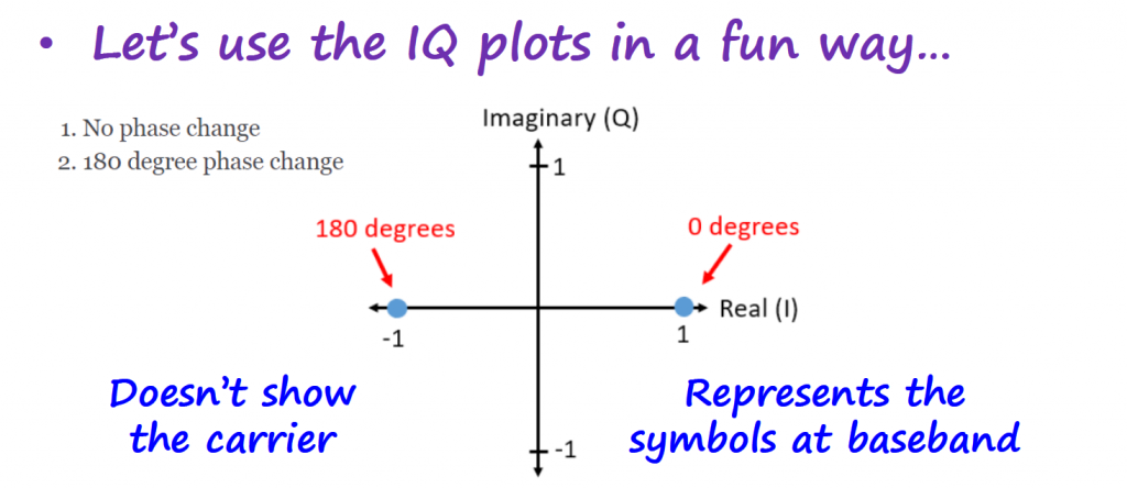
Have in mind that IQ plots do not show the carrier, it only represents the symbols used to modulate the baseband signal.

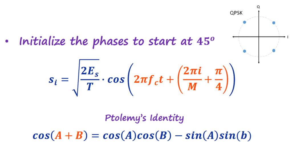
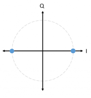
BPSK uses two symbols separated by 180 degrees between the symbols. For now, we are going to make things easy and assume that these symbols will always show up at these positions, meaning there is no phase rotation happening. We will cover on another article how to solve the issue of having the constellation moving around (not in sync).
Mapping Rules
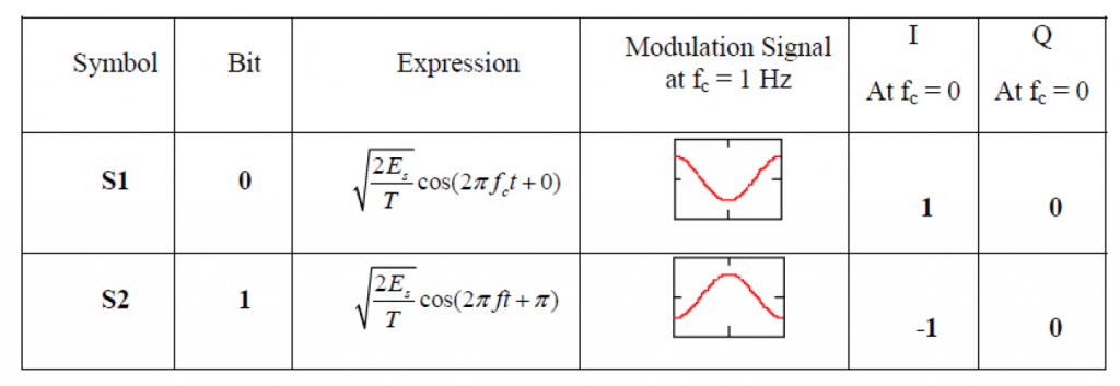
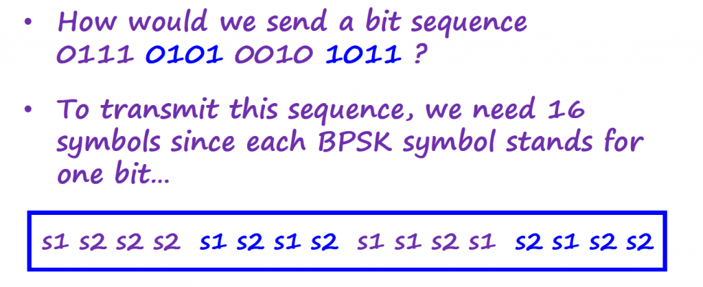
Let's go over on how to use BPSK to modulate a digital information signal. We start by mapping the bits to the symbols.
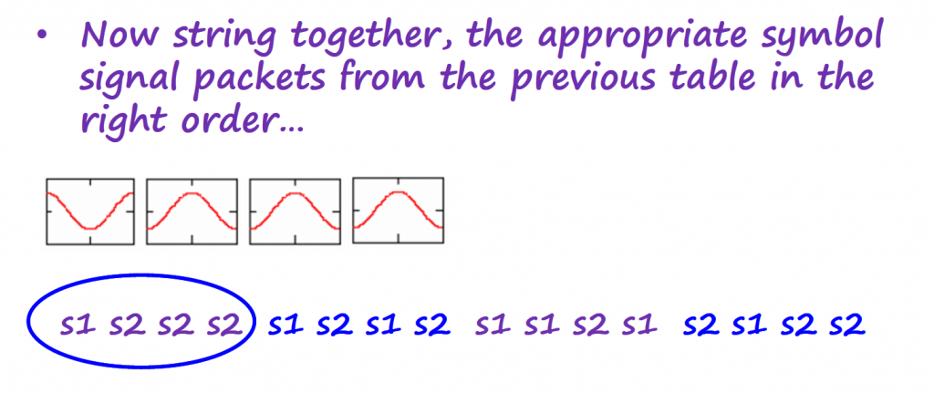
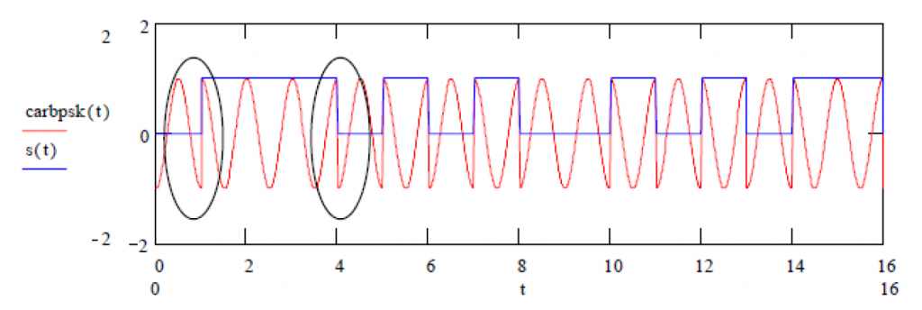
Complete time domain signal below.
GNURadio Example
We can use GNURadio to implement PSK schemes and get a visual of the IQ plot or constellations. As mentioned in the "Connection Between PSK and IQ Channels" section we don't need to include the blocks that implement the modulation with the carrier.
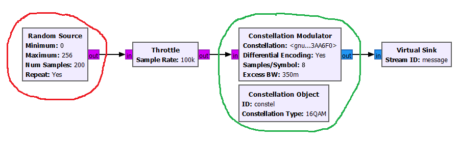
With that in mind, let's present a generic flowgraph that can be used for a good portion of PSK schemes.
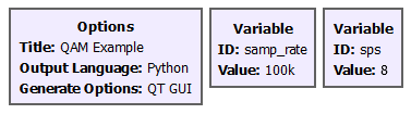
Variables
Modulation
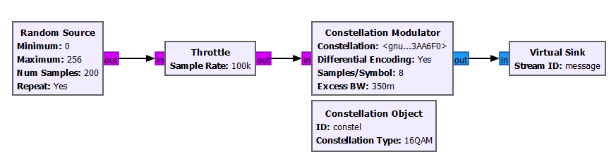
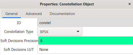
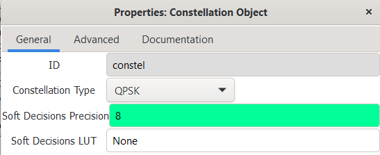
The Constellation Modulator block receives a input byte stream and outputs the complex modulated signal at baseband. It receives an ID constellation object provided by the Constellation Object block that contains the information of the constellation to use.
The Constellation Modulator block performs by default an RRC pulse shape function (controlled by the Excess BW parameter) to the received data. For more information about what this RRC is, you can read the "Shaping the Pulse to Reduce Bandwidth" section below. The Samples/Symbol parameter is used by the RRC shape function and it should be greater than 2. The Differential Encoding parameter allows to implement D-BPSK or BPSK. We will cover what differential encoding is on another article.
The Random Source block is generating random binary values from 0 to 255 (1 byte), with the right size to feed to the Constellation Modulator block. The Num Samples parameter is related with how many random samples will be generated per sample rate.
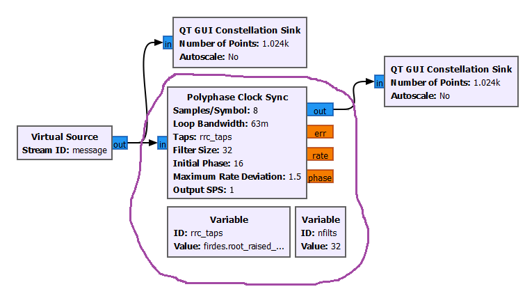
Demodulation
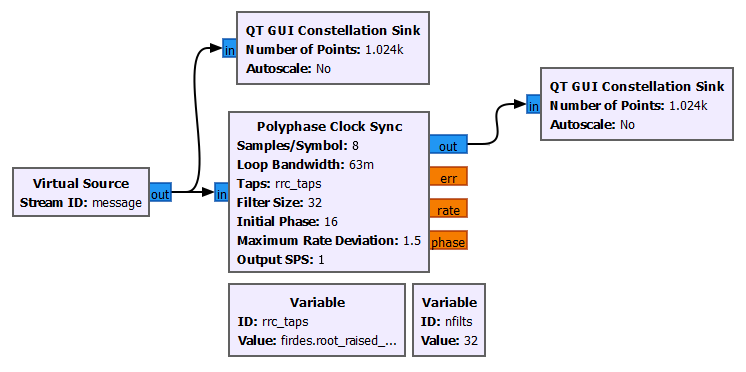
On the demodulation side of the transmission, we visualize the constellation without symbol synchronization and then the constellation after synchronizing the symbols with the Polyphase Clock Sync block.
QPSK
BPSK uses 1 bit per symbol, and the two symbols are separated by 180 degrees between them.
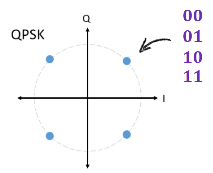
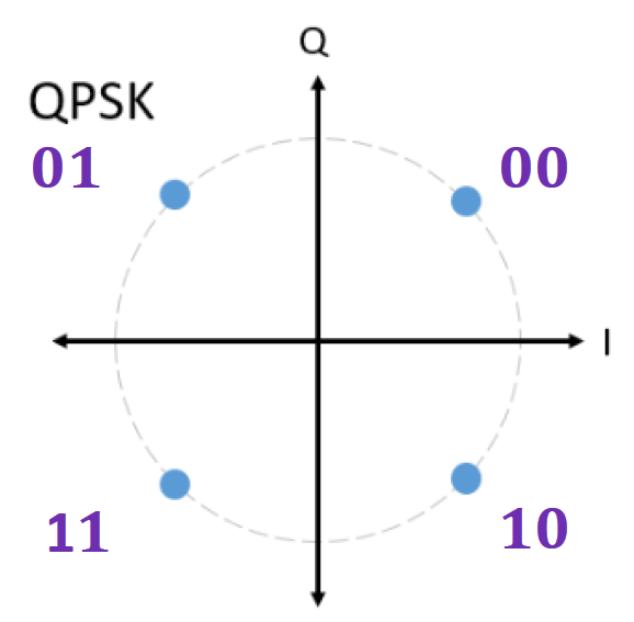
We have plenty of space in the complex plane to have more symbols. If we set 2 bits per symbol, we have 4 possible symbols and we can place them in the complex plane like the image below.
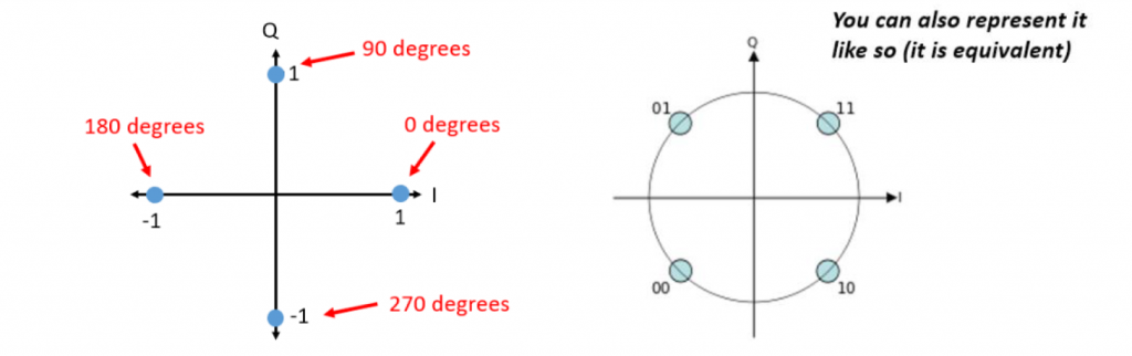
For 4 symbols we form a modulation scheme called Quadrature PSK (QPSK).
Mapping Rules
There are many ways to map the bits to the phases. The best way is to number them in such a way that each adjacent phase means just one bit difference. When mistakes are made then only one bit is decoded incorrectly.
This is called Gray coding and it is always applied in PSK schemes. In other higher order (M>4) PSK modulations, perfect gray ordering is not always possible.
Let's use the mapping below for the QPSK example.
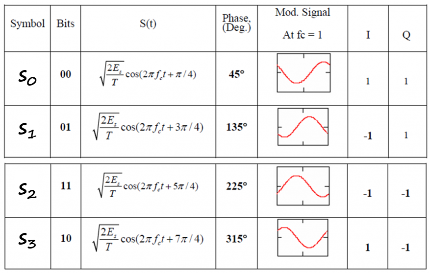
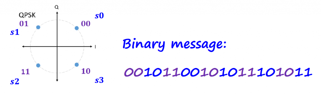
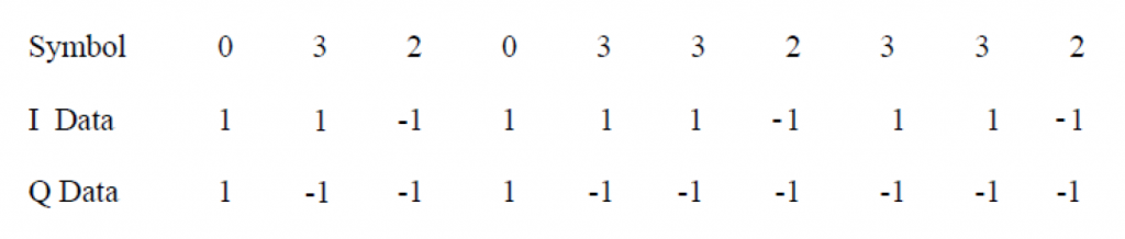
The I and Q are the information that will be sent to the IQ Modulator.
GNURadio Example
We can reuse the GNURadio flowgraph described for the BPSK scheme, and change the constellation to reflect the QPSK constellation. Everything else on that flowgraph is exactly the same.
Offset QPSK
You probably already notice that on the main GNURadio Articles page, the Digital Data to Analog Signal schemes are divided into Non-constant and Constant Envelope sections.
There is no rigorous definition for constant envelope:
- one definition states: there are no discontinuous phase changes;
- another definition states: when sampled at the symbol rate, the sampled value of the amplitude is constant;
- yet another: the maximum and minimum amplitude attained by the signal over one period is constant.
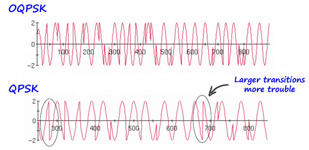
Constant envelope signals suffer less distortion in high power amplifiers and are preferred for wireless applications. QPSK is not technically a constant envelope because of its discontinuous phase shifts but it is considered nearly so.
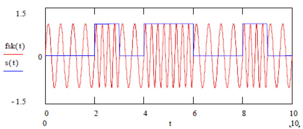
FSK is definitely a constant envelope.
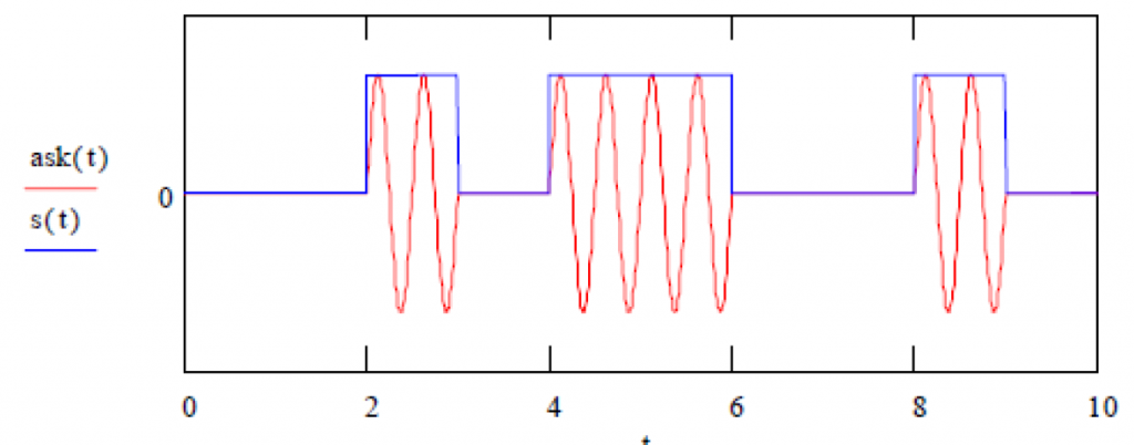
ASK is definitely not a constant envelope.
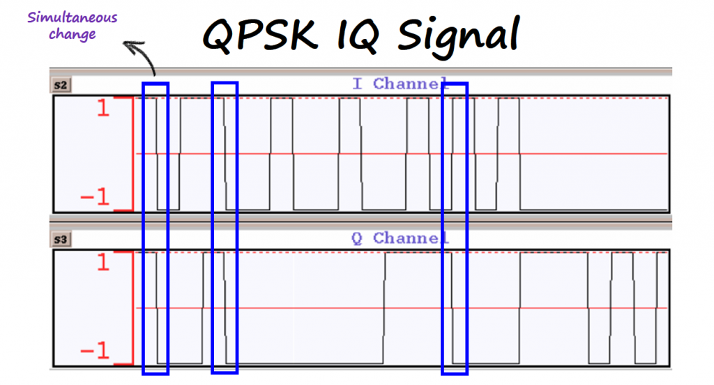
Offset QPSK (OQPSK) is a minor but important variation on QPSK. The Q channel is shifted by half a symbol so that I and Q channel signals do not transition at the same time. The result of this simple change is that phase shifts at any one time are limited and hence makes it more "constant" envelope.

In satellite transmission, QPSK reigns supreme, it is easy to build and operate. Military often uses OQPSK because of its need to use low power radios and minimum adjacent channel interference issues.
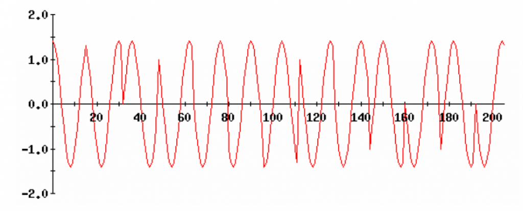
8-PSK
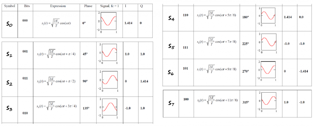
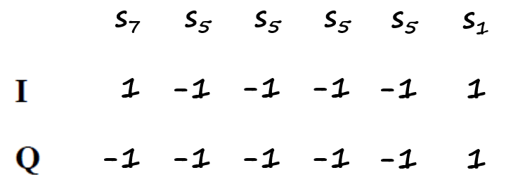
If we now use 3 bits per symbol, we can have a total of 8 symbols on the complex plane.
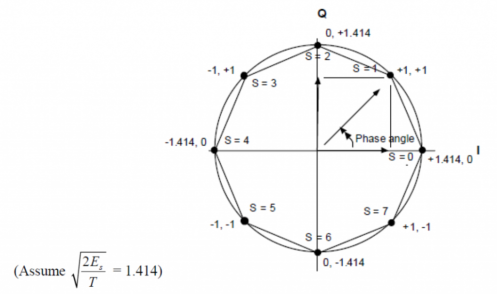
Mapping Rules

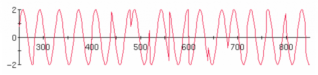
8-PSK transmitted signal shows smaller phase transitions (on the average) than QPSK. However, signals are also less distinctly different from each other, which makes 8-PSK prone to higher bit errors.
The throughout of 8-PSK is 50% better than QPSK which can transmit just 2 bits per symbol as compared to 3 for 8-PSK.
8-PSK is the first of the bandwidth-efficient modulations.
π/4 QPSK
This is a variation of QPSK that mimics 8-PSK. Note that an 8-PSK constellation can be broken into two QPSK constellations.
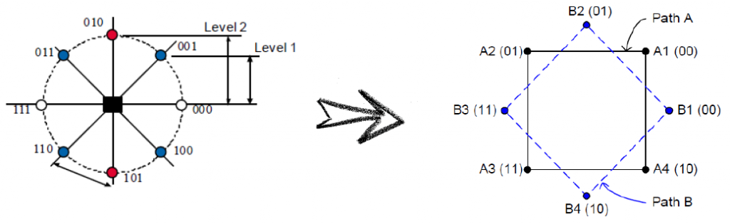
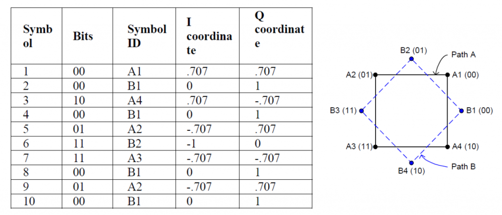
In π/4-QPSK, one symbol is transmitted on the A constellation, and the next one is transmitted using B constellation.
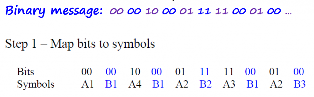
Mapping Rules
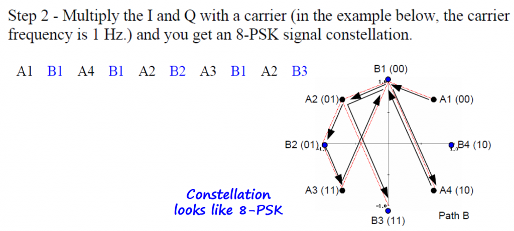
On the average, the phase transitions are somewhat less than a straight QPSK.
16-PSK
We can keep subdividing the signal space into smaller regions.
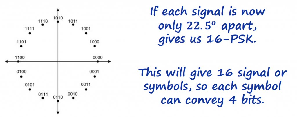
We can see where this is going. We can keep on increasing bits per symbol this way. However, 16-PSK is rarely used. Even though 16-PSK is bandwidth efficient, it has a higher bit error rate than a common modulation from the class of Quadrature Amplitude Modulation called 16-QAM (check "QAM Modulation" section) which has the same bit efficiency.
Shaping the Pulse to Reduce Bandwidth
Let's bring back the equation for the PSK schemes, and let's cover the pulse shaping function argument of it.
Square Pulse
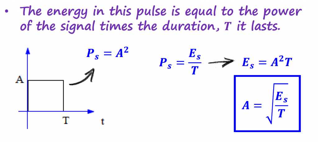
Using square pulses to represent baseband PSK signals, we get the following
It is common to find these equations written in terms of the power we wish to pass on to the signal. This power is the connection between symbols and antennas used to transmit the information through the medium.
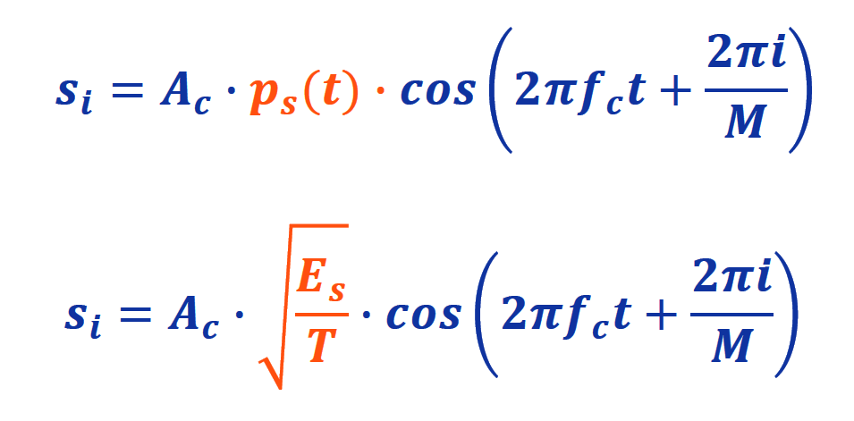
For convenience we can set Ac=√(Es)

Which in turn leads to the general PSK modulation equation.
For didactic purposes, we normally assume that √(2Es/T) = 1. In real life, both T and Ac have different values than 1 (the majority of the times smaller than 1).
The square pulses used in the pulse shaping function are not practical to send, because they are hard to create and require a lot of bandwidth. With that, we send shaped pulses that convey the same information but use smaller bandwidths and have other good properties.
Some common pulse shaping methods:
- Root Raised Cosine (RRC), used with QPSK
- Half-Sinusoid, used with MSK
- Gaussian, used with GMSK
- Quadrature Partial Response, used with QPR
RRC Pulse
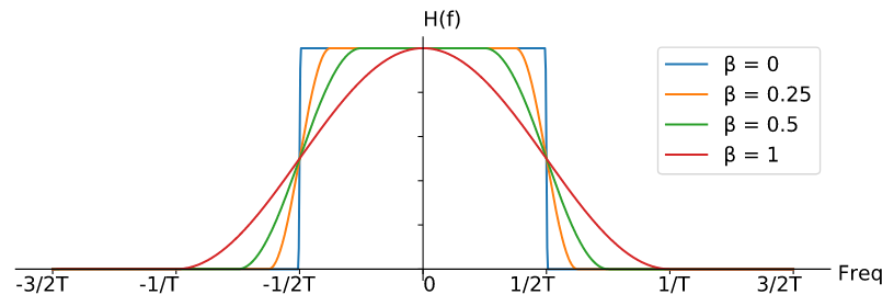
RRC pulse is the most common pulse shape function for PSK modulation schemes. It is a low-pass filter for limiting the bandwidth of the signal, and it has the property of summing to zero at intervals of T. This property will be useful to avoid inter-symbol-interference (ISI) when transmitting the modulated symbols.
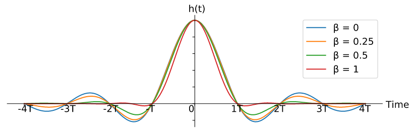
The RRC pulses have the following frequency response:
We can use GNURadio to get an idea on how a digital signal looks like after applying an RRC filter. I encourage to run the flowgraph and play around with different values for the taps, alpha and symbol_rate parameters and see how that changes the time and frequency response of the information signal.
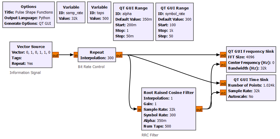
On a PSK scheme flowgraph, RRC can be applied before sending the signal to the IQ modulator.
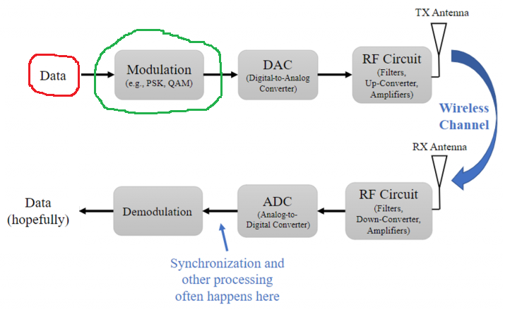
GNURadio Flowgraph <=> Tx-Rx Chain Block Diagram
We implemented PSK schemes with GNURadio flowgraphs, and this section goal is to relate some of these flowgraphs with the Tx-Rx Chain block diagram introduced in the Intro section of the Analog Data to Analog Signal topic.
Modulation
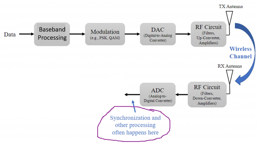
Demodulation
GNURadio Files
- BPSK Example
- QPSK Example
- Pulse Shapes Example
References
- [Ref 1] “PySDR: A Guide to SDR and DSP using Python”, PySDR Website [Articles]
- [Ref 2] “Tutorial 8: All About Digital Modulation”, Complex to Real Website, Charan Langton [Article]
- [Ref 3] “Tutorials on Digital Communications”, Complex to Real Website, Charan Langton
- [Ref 4] “Summary of Trigonometric Identities”, Clark University [Article]
- [Ref 5] “Modern Digital and Analog Communication Systems”, B. P. Lathi and Zhi Ding [Book]