AM Modulation
This article focus on the classic analog Amplitude Modulation (AM), and its derivations.
Note: The article combines mathematical expressions with visuals with the goal to help understanding the concepts from different perspectives. The goal by presenting math equations is not to overwhelm the reader but rather an attempt to connect the theory with the practical world.
Baseband and Passband Signals
The term baseband is used to designate the frequency band of the information signal from the source or the input of your communication system. In telephony, the baseband is the audio band (band of voice signals) from 0 to 3.5 kHz. In analog NTSC television, the video baseband is the video band occupying 0 to 4.3 MHz.
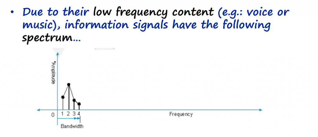
Because most baseband signals contain significant low-frequency content, they cannot be effectively emitted over radio (wireless) links. Instead we rely on carrier modulations techniques to transmit the information over wireless links.
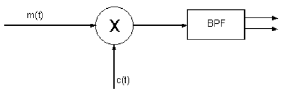
Modulation can be achieved in several ways. The simplest type of modulator for nearly all modulation schemes is called Product Modulator. Remember that the goal of modulating a signal, is to load the information signal (m(t)) into the carrier (c(t)). The frequency of the carrier is generally way higher than the frequencies of the information signal and that is useful for transmitting the information signal over longer distances.
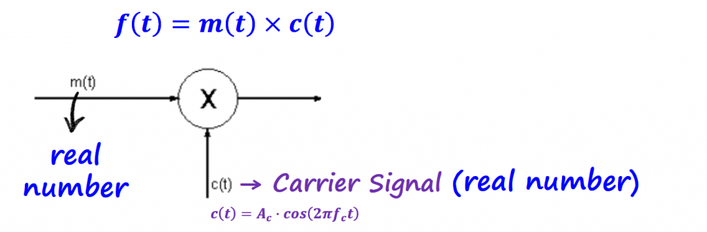
For AM modulation schemes, the information signal is a real number. The carrier is also a real number and the modulated signal will also be a real number.
In terms of spectrum for digital communication systems, the exponential form of the Fourier Series is normally used to represent signals in the frequency domain. The reason behind that choice is because IQ channels (technique used by different types of modulation schemes) contain complex numbers that represent positive and negative frequencies. I will cover the different ways of writing the Fourier series on another article, but for now we will use the exponential form.
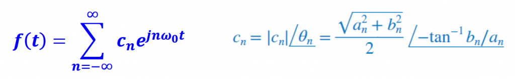
With that, we have positive and negative frequencies of the information signal, carrier and modulated signal in the spectrum. In this particular case, the negative frequencies are identical to the positive frequencies because our signals are real numbers. Real numbers have the same positive and negative spectrum.
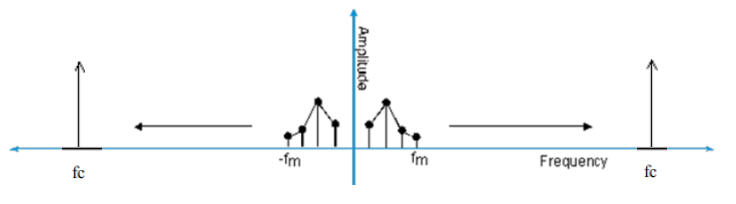
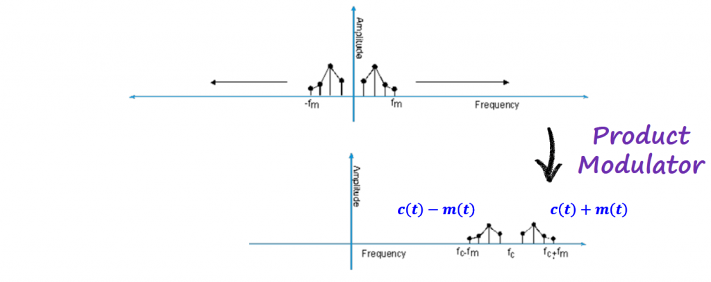
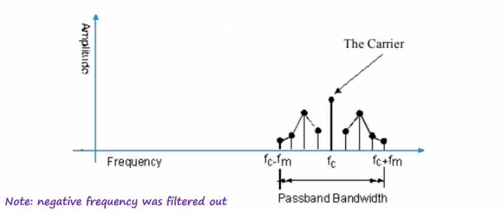
Going back to the product modulator, multiplying a signal in time with a pure sinusoidal waveform, corresponds to shifting the spectrum of the information signal in the frequency domain by the carrier frequency.
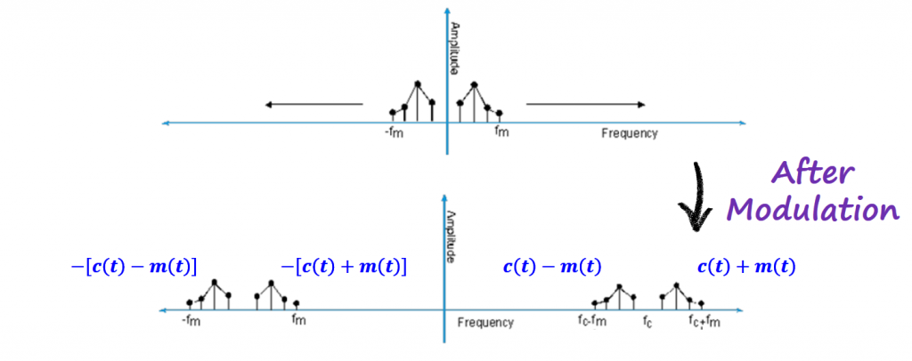
Note: fc is the frequency of the carrier, and fm is the maximum frequency of the information signal.
The negative frequency is usually no problem and can be filtered out by a real passband filter.
In terms of time domain signals, we get the information signal to modulate the amplitude of the carrier signal.
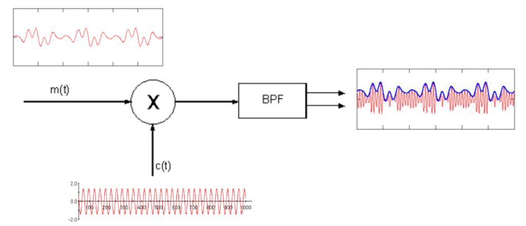
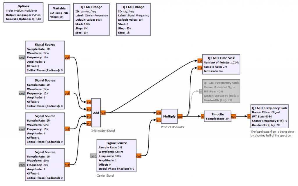
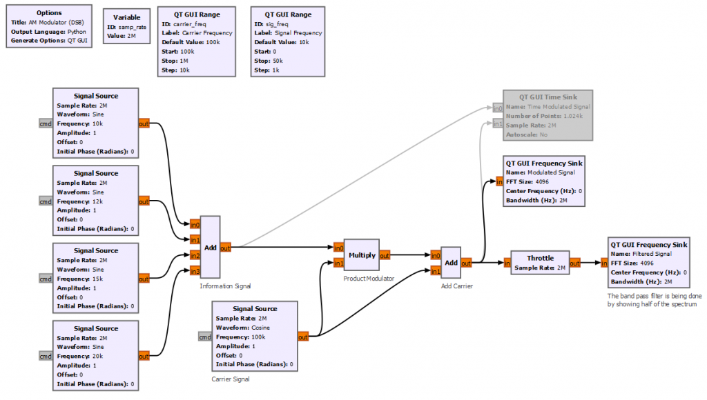
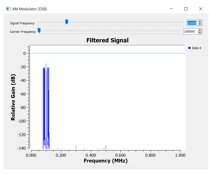
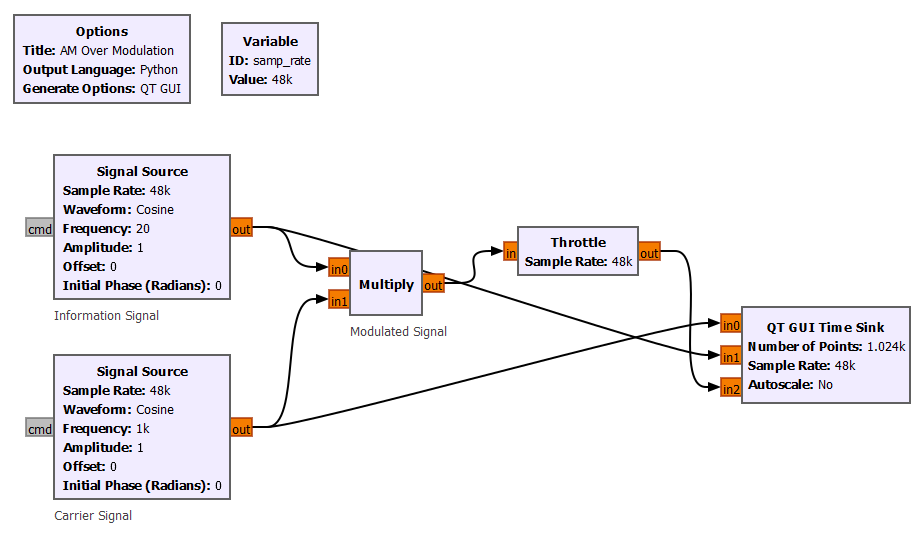
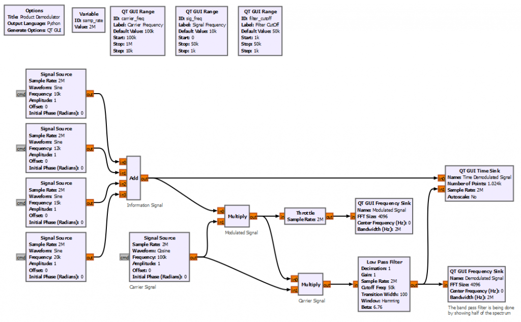
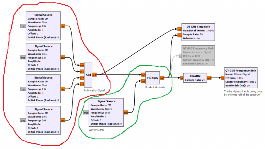
Let's start by implementing the simplest product modulator with GNURadio. For simplicity the block diagram below creates 4 different sinusoidal waveforms with frequencies between 10 to 20 kHz. The carrier frequency is set to 100 kHz.
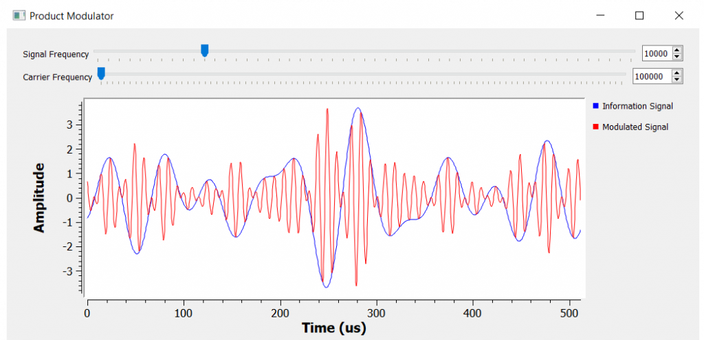
The time domain signal has a small problem that we will be fixing it soon, but for now we can see the amplitude of the carrier (red line below) being modulated by the information signal (blue line below).
Some New Terms:
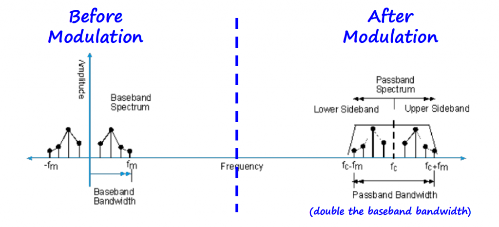
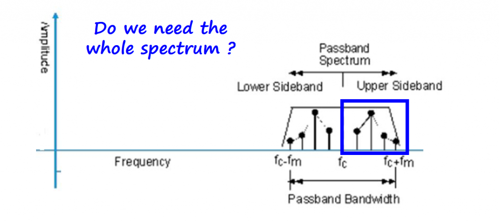
After modulating the signal, we have some new terms emerging. The information signal (m(t)) spectral components contribute to what is called Lower and Upper sidebands. We also have the passband bandwidth which is the double of the original information signal (or baseband) bandwidth.
Sidebands (DSB and SSB)
At this point you might be wondering that after modulating the information signal, the spectrum is redundant and we probably don't need all that information to recover the information signal.
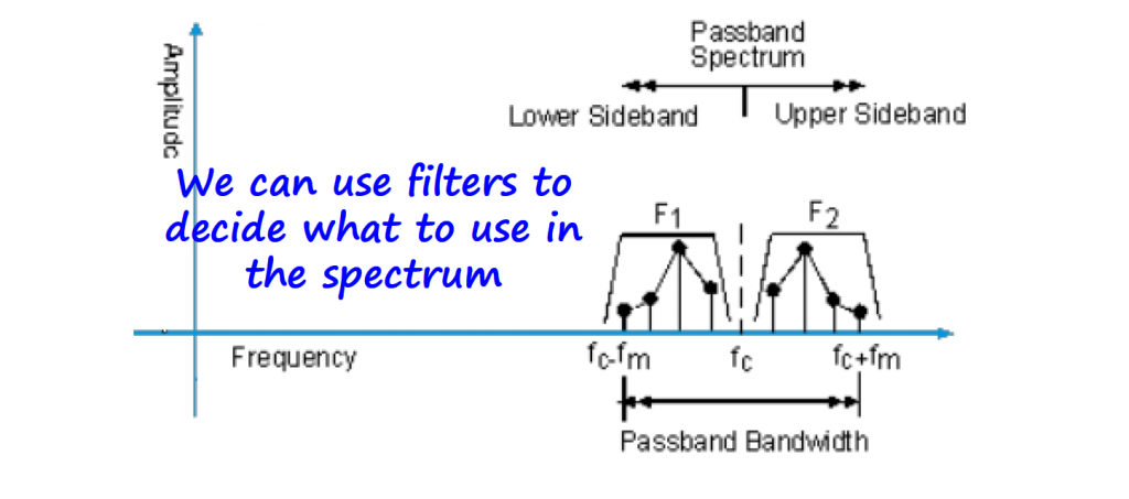
Depending on the type of filter selected, we can have two types of AM modulation.
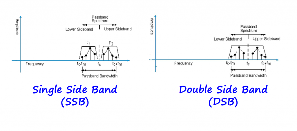
Double Sideband (DSB)
Instead of transmitting just the information signal multiplied by the carrier, we can add the carrier to the product. Adding the carrier to the modulated signal can offer some advantages when demodulating the received signal to recover the information signal.
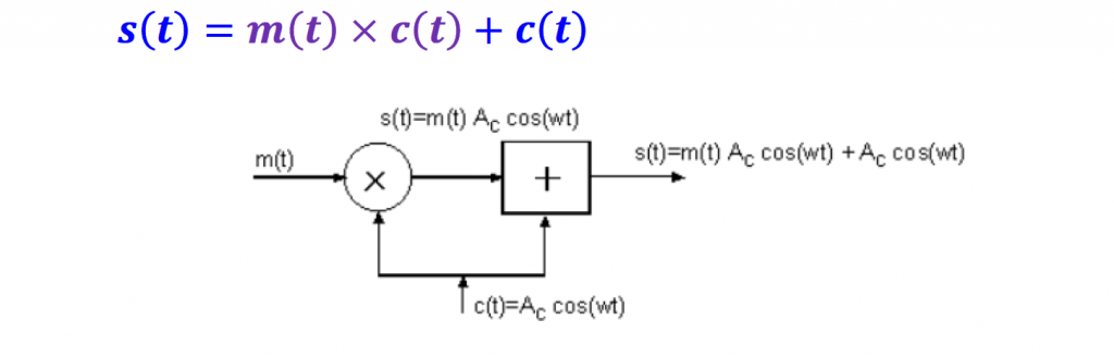
This is the most basic form of AM modulation called Double Sideband (DSB) modulation.
Notice on how the carrier is now present in the spectrum. Including the carrier into the modulated signal is a technique that will be useful for coherent demodulators (or synchronous demodulators).
The practical implications of using DSB is that the transmitter needs to transmit at a much higher power level, which increases its cost as a trade-off.
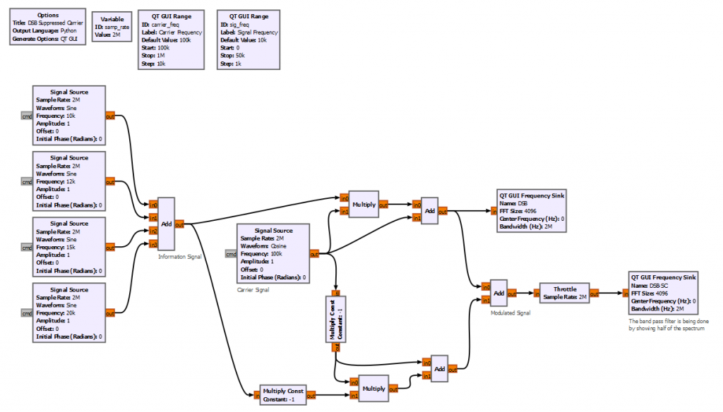
Double Sideband - Suppressed Carrier (DSB-SC)
We just added the carrier, but now realize that it actually takes a lot of power to transmit the modulated signal. Depending on the trade-offs of our communication system, we might want somehow to include the carrier information but without actually doing so.
To solve that issue, we rely on the symmetry of the signal spectrum and build a balanced modulator.
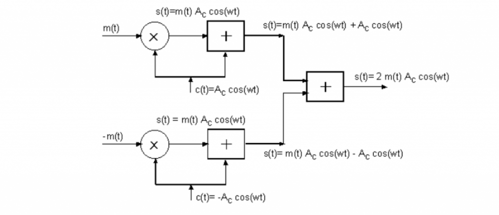
The decision when to use DSB or DSB-SC depends on the requirements of your applications.
For example, in point-to-point communications, where there is one transmitter for every receiver, substantial complexity in the receiver system can be justified if the cost is offset by a less expensive transmitter. On the other hand, for a broadcast system with a huge number of receivers for each transmitter, where any cost saving at the receiver is multiplied by the number of receivers units, it is more economical to have on expensive, high-power transmitter, and simpler, less expensive receivers. For this reason, broadcasting systems tend to favor the trade-off by migrating cost from the (many) receivers to the (few) transmitters.
Single Sideband (SSB)
SSB is a bandwidth conserving technique. The passband signal and the baseband signal occupy the same bandwidth, so cutting the spectrum needs in half.
There are three ways to create a SSB signal:
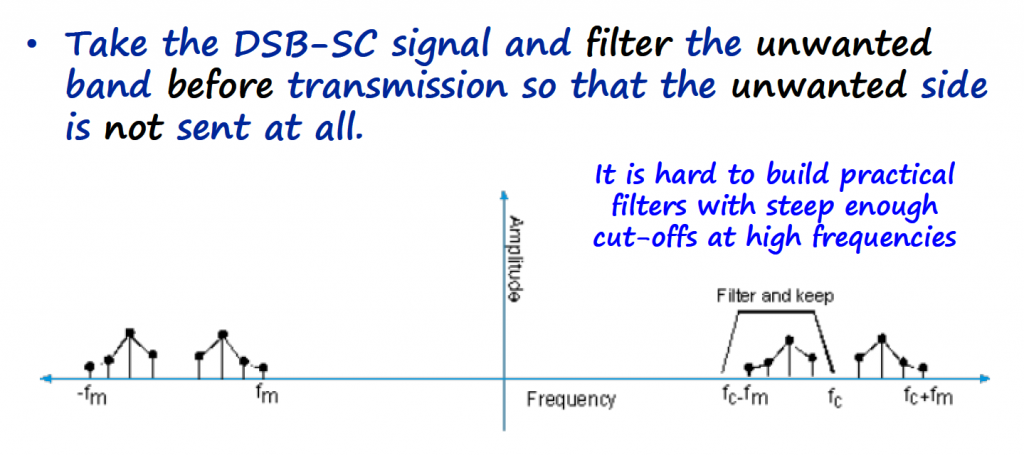
- Filtering the unwanted sideband
- Phasing method
- Weaver method
Filtering Method
Phasing Method
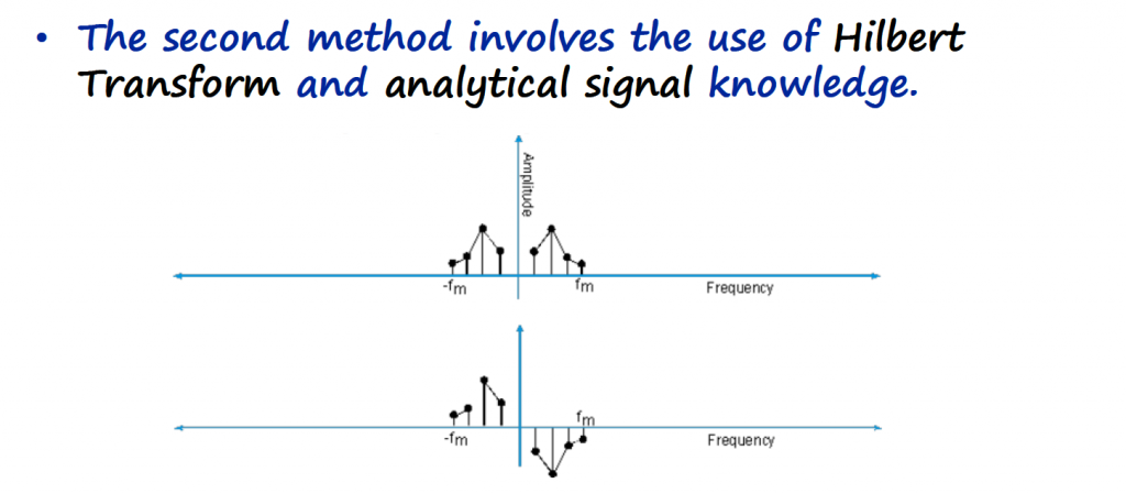
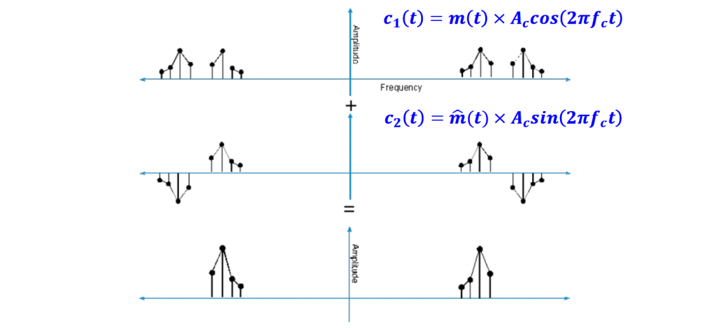
The SSB modulator applies the Hilbert transform to the information signal creating two signals in quadrature.
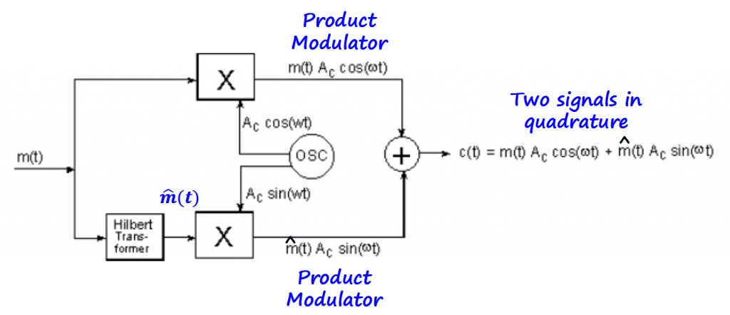
In terms of spectrum, the final result is a clean single band with nothing to filter.
You can read [Ref 3] for more information about what an Hilbert transform is.
Weaver Method
In 1956 Donald Weaver published a method in the Proceedings of the IRE ("A Third Method of Generating and Detecting Single Side Band Signals", Dec. 1956). It involves the use of a local oscillator with a frequency in the middle of the audio spectrum (1500Hz) for the I and Q signals separately, and then adding or subtracting them to recover the upper or lower sideband audio.
GNURadio has a SSB example using the Weaver method on the tutorials page (Link). This tutorial explains how a SSB signal can be generated and received.
Over Modulation
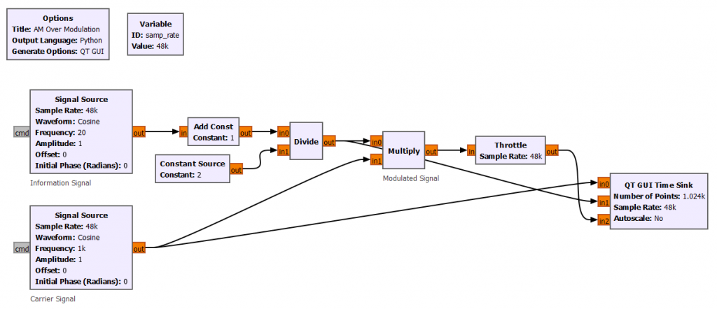
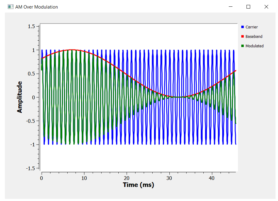
All the examples that we saw so far suffer from a problem called phase inversion or over modulation. To understand what this problem is, let's go back to the product modulator block diagram, set the information signal to a single sinusoidal waveform, and visualize the output waveform in time.
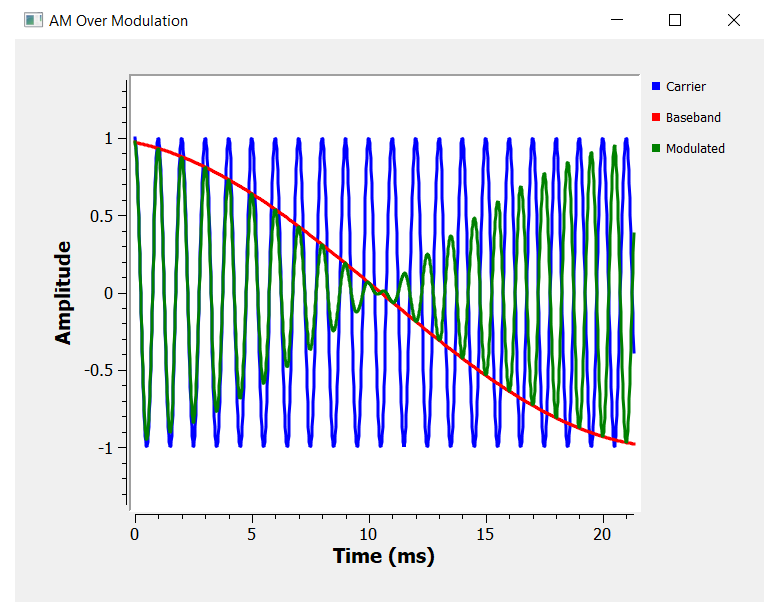
Notice that the baseband signal (or information signal) doesn't follow the amplitude of the modulated signal. We see an undesired phase inversion that it is called over modulation.
One way to fix this issue, is to add an offset value and reduce the amplitude of the information signal.
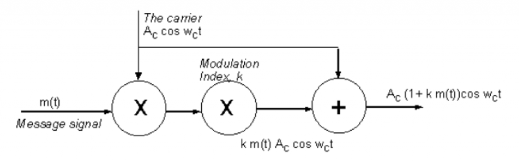
For a standard DSB modulation, the over modulation issue is addressed by adding a modulation index k to the block diagram. The modulation index should be less or equal to 100%
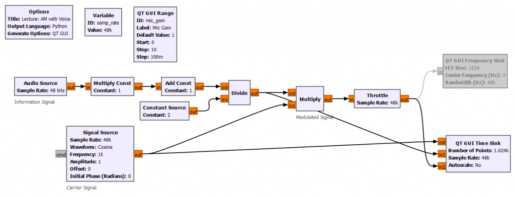
AM Voice Transmitter Example
We can make the over modulation GNURadio project a bit more realistic. We can substitute the signal source by an audio source module (the microphone), and modulate the carrier with our voice.
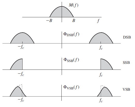
Vestigial Sideband (VSB)
The generation of exact SSB signals is rather difficult, and the generation of DSB signals is much simpler but requires twice the signal bandwidth. VSB modulation system, also called asymmetric sideband, is a compromise between DSB and SSB. It inherits the advantages of DSB and SSB but avoids their disadvantages at a small price.
VSB signals are relatively easy to generate, and, at the same time, their bandwidth is only somewhat (typically 25%) greater than that of SSB signals.
In VSB, instead of rejecting one sideband of the DSB-SC spectrum completely as SSB does, a gradual cutoff of one DSB-SC sideband (as shown below) is accepted.
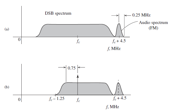
VSB is adopted in both the analog NTSC television system and the ATSC Digital Television Standard. Under the FCC requirements, the standard video signal occupies a bandwidth of 4.5 MHz, and the sound signal is separate and it is transmitted at the upper edge of this signal.
Figure a) below shows the entire DSB spectrum and b) shows the actual VSB signal transmitted after filtering one sideband, reducing the bandwidth of the transmitted signal.
Demodulators
The received AM signal must be demodulated, that is, the information signal (baseband) must be recovered (reconstructed). There are several ways to do this:
- Envelope Detection
- Square-Law Demodulation
- Synchronous Product Demodulation (coherent demodulator)
- Asynchronous Product Demodulation (incoherent demodulator)
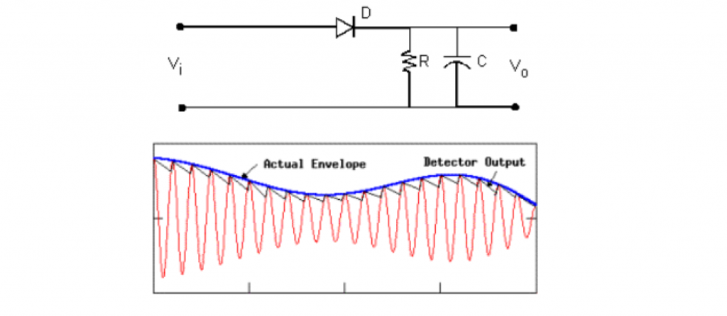
Envelop Detectors
A diode circuit is used most often to detect the envelop of AM signals and is the universal method of demodulating AM signals.
There are a couple of prerequisites though:
- Presence of a strong carrier
- High Signal to Noise Ratio (SNR)
Since we are dealing with SDRs, this demodulator is not feasible to implement.
Asynchronous Product Demodulator
All AM signals discussed here, DSB, DSB-SC, SSB, and VSB can be demodulated using an asynchronous product demodulator.
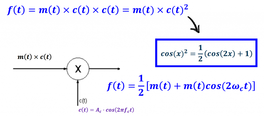
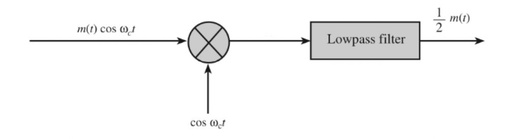
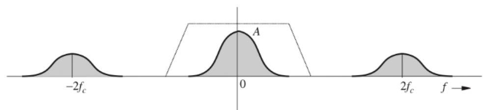
To recover the information signal, we apply a low pass or band pass filter at the end of the product modulator.
Since the carrier phase is not known, the phase of the carrier at the receiving end is not synchronized with the transmitter.
In radio AM broadcasting we can get away with ignoring the phase because our ears are not very sensitive to phase deviations of the signal. We can use incoherent demodulators (like the asynchronous product modulator).
Synchronous Product Demodulator
Now if we are sending digital data, synchronization is indeed a big problem, and we need to exactly recover the phase of the transmitted carrier.
There are two methods to recover phase:
- The Costas Loop (Link)
- The Phase Locked Loop (PLL)
These are called coherent demodulations.
GNURadio Flowgraph <=> Tx-Rx Chain Block Diagram
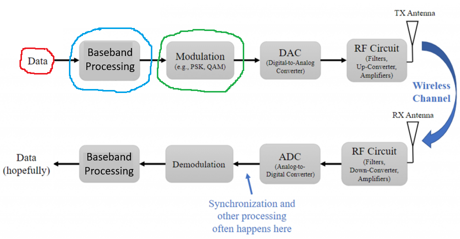
We have been implementing the AM schemes with GNURadio flowgraphs, and this section goal is to relate these flowgraphs with the Tx-Rx Chain block diagram introduced in the Intro section of the Analog Data to Analog Signal topic.
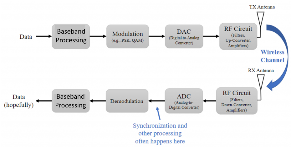
I believe there is value to spend some time understanding this level of abstraction because flowgraphs can easily become complex and overwhelming. Connecting the GNURadio blocks into the Tx-Rx Chain block diagram can help with the understanding of more complex flowgraphs.
Modulation
Let's examine 3 flowgraphs and relate them to the transmitter side of the Tx-Rx Chain block diagram.
Simple Product Modulator Example
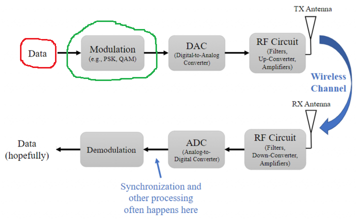
For all AM schemes the information signal (or baseband signal) is an analog signal. If there is no signal processing on the information signal, meaning your input signal on the flowgraph connects directly to the Multiply block, that means that the data on the Tx-Rx Chain block diagram (highlighted in red on the flowgraph below) can connect directly to the Modulation block (highlighted in red on the block diagram below).
This AM scheme flowgraph uses the Product Modulator to modulate the information signal into the carrier. That means, the Multiply block in conjunction with the carrier Signal Source block from the flowgraph (highlighted in green) are part of the Modulation block (highlighted in green) in the Tx-Rx Chain block diagram.
SSB Transmitter Example
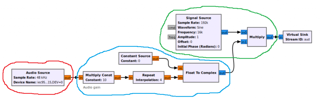
If the input signal on the flowgraph has additional blocks between it and the Multiply block (highlighted in blue) then we include the Baseband Processing block between the data and the Modulation block (highlighted in blue) on the Tx-Rx Chain block diagram.
In this case the Modulation block stays the same (highlighted in green).
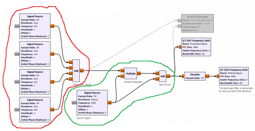
DSB Example
For this 3rd example, there is not signal processing on the information signal. However, the Modulation block (highlighted in green) has some additional blocks associated with it.
Demodulation
Let's examine 2 flowgraphs and relate them to the receiver side of the Tx-Rx Chain block diagram.
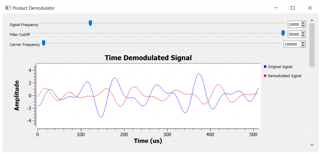
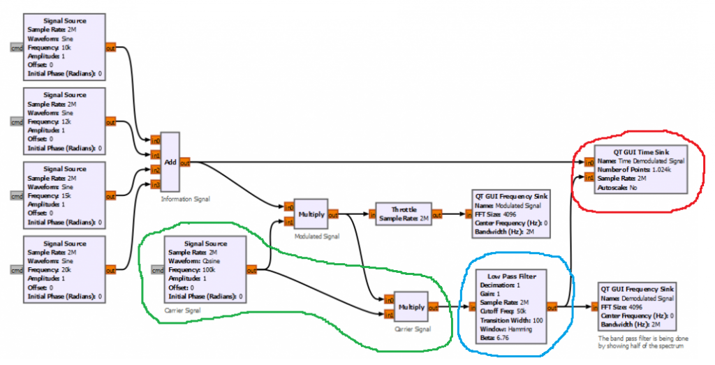
Async Product Demodulator Example
This example uses an asynchronous product modulator to bring the information signal (or baseband signal) down the spectrum (highlighted in green) to a position where we can apply a low pass filter (highlighted in blue) to recover the information signal (highlighted in red).
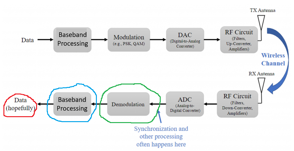
Heads up that some GNURadio modules (for example the Frequency Xlating FIR Filter) will do these two operations in one block, making it ambiguous to consider if it belongs to the demodulation module or to the baseband processing module.
When analyzing flowgraphs, as long as you are aware of what is going on, it is up to you where you place the modules. What is important is to keep some sort of documentation or description or note informing if the module is doing more than what is supposed to do.
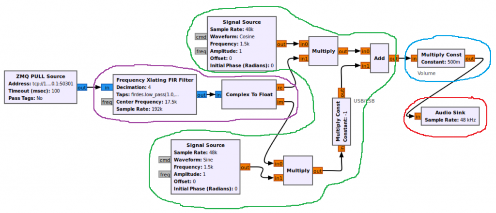
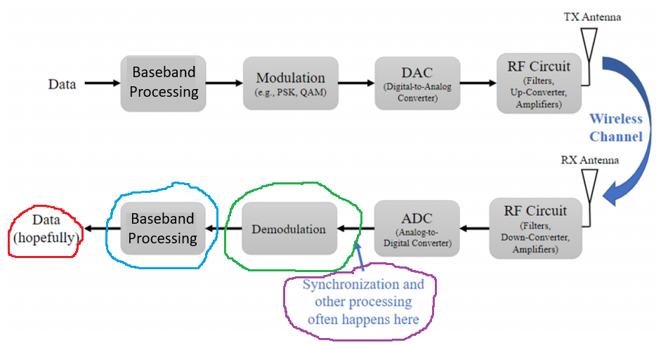
SSB Receiver Example
This example is very interesting to analyze because it is applying SSB demodulation using the Weaver method. Briefly, the Weaver method applies two frequency translations on the signal. The first translation is done at the frequency of the carrier, and the second translation is done at an auxiliary frequency in the middle of the information signal spectrum (normally at 1500 Hz).
The Frequency Xlating FIR Filter (highlighted in purple) is applied first to the received signal to remove the frequency of the carrier, and it also applies a low pass filter. The signal is then frequency translated again (highlighted in green) to recover the upper or lower sideband of the information signal.
On the Tx-Rx Chain block diagram, I considered what is highlighted in purple, to be part of a pre-processing block before demodulating the signal to recover the upper or lower sideband information. It would have been totally fine to consider all the frequency translations part of the demodulation block.
There is not much baseband processing happening here, but to use it as an example, I considered the Multiply Const block a baseband processing module.
I hope these examples help with the understanding of other flowcharts in the future.
GNURadio Files
- Product Modulator Example
- DSB Modulation Example
- DSB-SC Modulation Example
- SSB Transmitter Example
- SSB Receiver Example
- Over Modulation Issue Example
- Over Modulation Solved Example
- Async Product Demodulator Example
- Voice AM Modulation Example
References
- [Ref 1] “PySDR: A Guide to SDR and DSP using Python”, PySDR Website [Articles]
- [Ref 2] “Tutorial 9: Baseband, Passband and Amplitude Modulation (AM)”, Complex to Real Website, Charan Langton [Article]
- [Ref 3] “Tutorial 7: Hilbert Transform and the Complex Envelope”, Complex to Real Website, Charan Langton [Article]
- [Ref 4] “Tutorials on Digital Communications”, Complex to Real Website, Charan Langton
- [Ref 5] “Summary of Trigonometric Identities”, Clark University [Article]
- [Ref 6] “Modern Digital and Analog Communication Systems”, B. P. Lathi and Zhi Ding [Book]