FSK Modulations
This article focus on Frequency Shift Keying (FSK), which belongs to a digital modulation scheme available to transmit digital data.
Note: The article combines mathematical expressions with visuals with the goal to help understanding the concepts from different perspectives. The goal by presenting math equations is not to overwhelm the reader but rather an attempt to connect the theory with the practical world.
FSK Modulation
As discussed in the Angle Modulations article there are 3 possible ways to modulate information signals into the carrier.
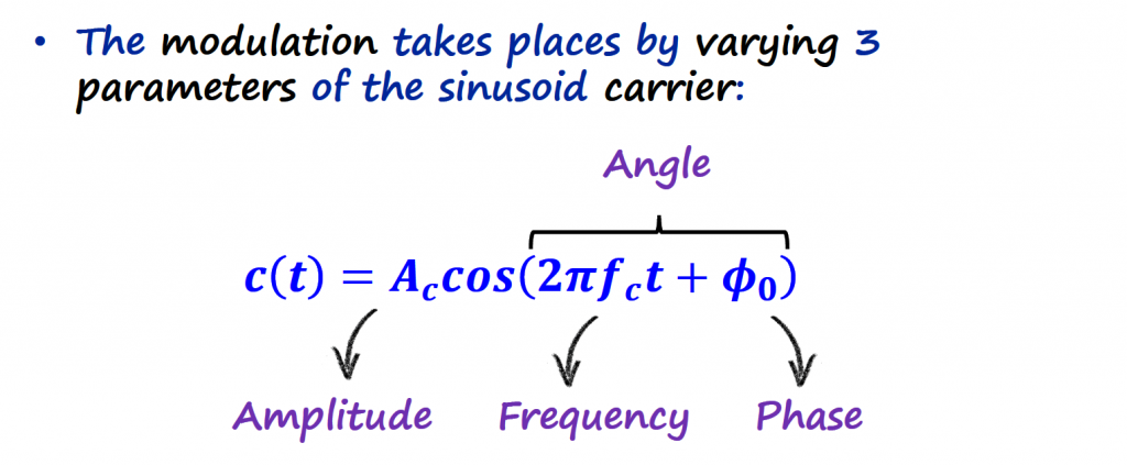
The digital version of FM is called Frequency Shift Keying (FSK). With FSK schemes, the carrier frequency is varied in proportion to the information signal (m(t)), but this signal is now a digital signal rather than analog.
Generic FSK
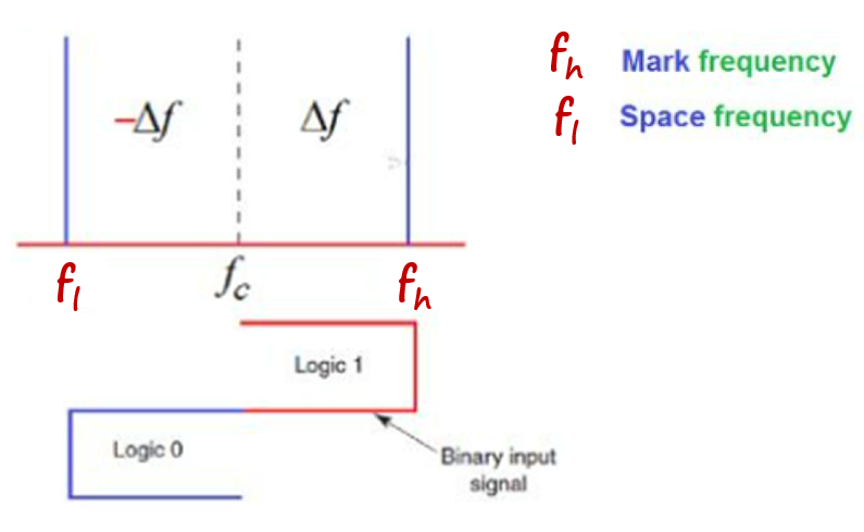
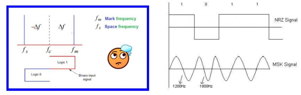
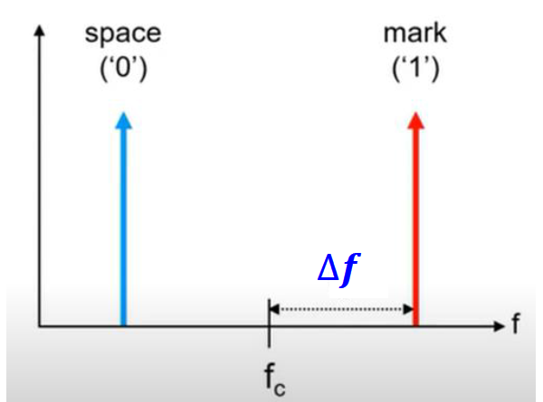
Let's start by describing the generic way on how FSK modulates an information signal with just one bit (N=1). With one bit we have 2 possible symbols (21=2 symbols). The modulation signal will consist of two different carriers to represent these 2 symbols. One carrier to represent the "0" (also called space) and another carrier to represent the "1" (also called mark). Normally the carrier that represents the "0" is called fl (frequency low) and the carrier that represents the "1" is called fh (frequency high).
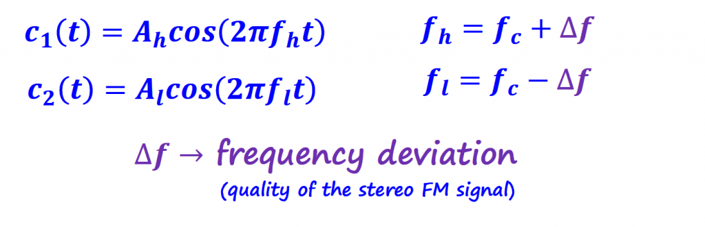
We will cover more about what Δf to choose later. For now we are just aware that we can tune this parameter according to our needs.
Conversion Table
Since we are dealing with two different carriers to represent the binary information, we need to find a way to map the zeros and ones of the information signal to the carriers. We need a conversion table.
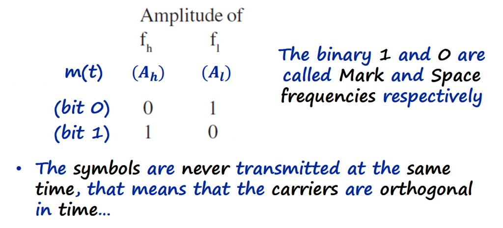
With this, we have access to the amplitude of the carriers, meaning access to Al (amplitude of the space) and Ah (amplitude of the mark), and we can use the binary numbers of the information signal to "turn on and off" the respective carrier.
The binary information signal is transmitted one bit at the time, which means that we will never have the space and the mark happening at the same time.
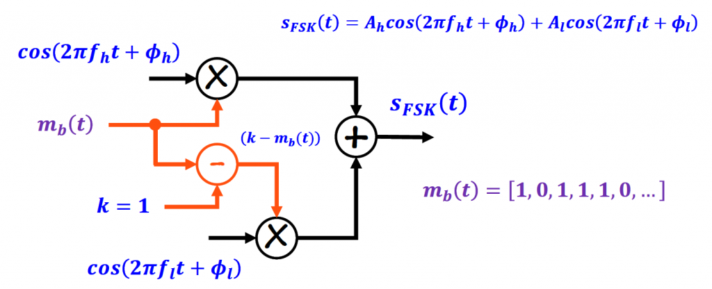
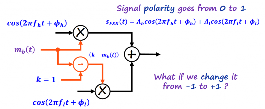
Simple FSK Modulator
With the conversion table in place, we are in good shape to design a simple FSK modulator. This modulator is not too much different than the analog FM modulator shown in the "Analog FM" section. The only difference relies on preparing the digital data before sending it to the FM Mod block.
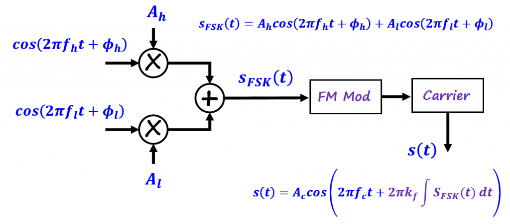
The signal sent to the FM Mod block (SFSK) will be a single sinusoidal frequency at the time. We can also incorporate a mechanism to change the amplitudes in an alternated way using only one binary input.
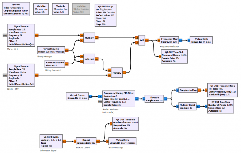
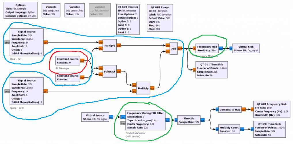
Let's create the GNURadio flowgraph for the block diagram above.
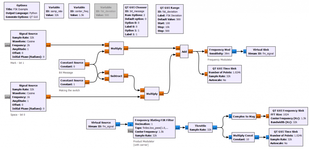
The Add block outputs the SFSK signal that enters the FM Mod block. The Virtual Sink and Virtual Source blocks are used to connect blocks together without using wires.
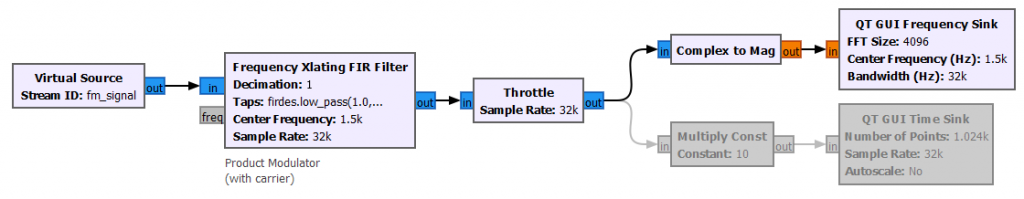
The Frequency Xlating FIR Filter block executes the modulation between the FM information signal and the carrier (it shifts the information up the spectrum). The remaining blocks are used to visualize the modulated signal.
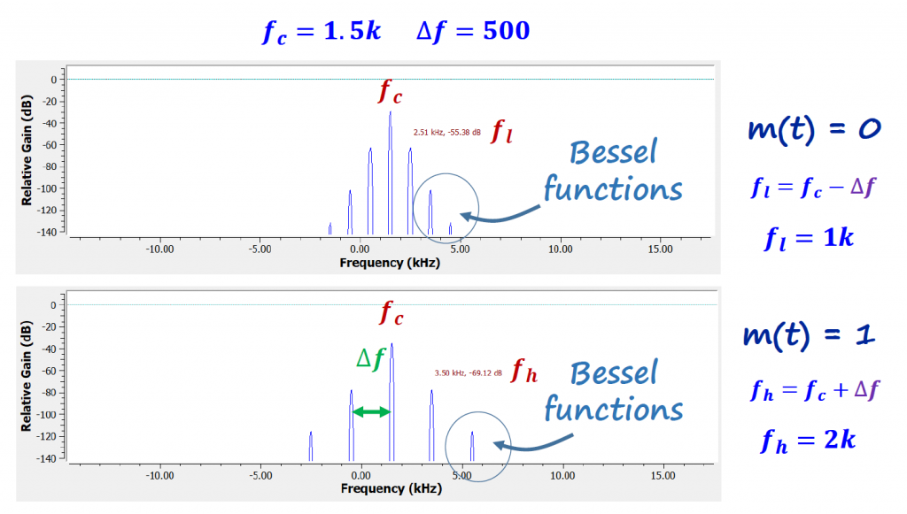
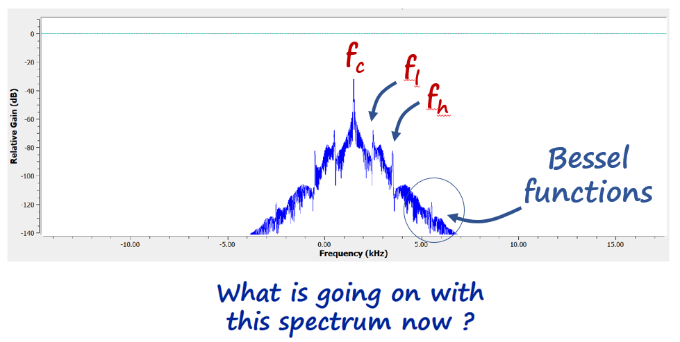
Alternating the information signal between 0 and 1, we can see the spectrum changing accordingly. If we analyze the spectrum carefully, we can see the presence of the carrier (fc), the information signal (fl and fh), and sidebands related to the FM modulation (due to Bessel functions - read the "Analog FM" section).
Simple FSK Modulator with Bit Rate Control
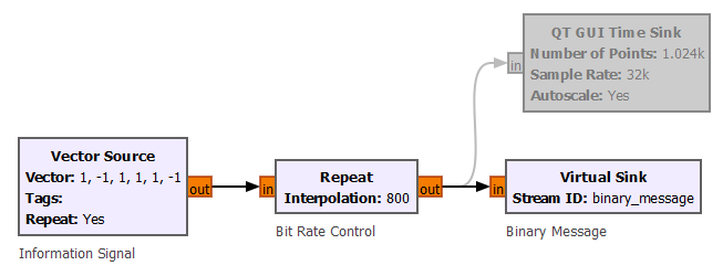
In the previous section we were changing the binary information signal manually. Let's incorporate this change using a Vector Source block that contains the binary information signal.
The Repeat block in front of the Vector Source block is used to control the frequency of the information signal (or bit rate for a digital signal).
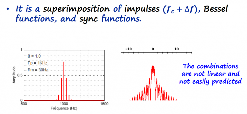
If we look at the spectrum of the modulated signal, we can see that it has more spectral information. The carrier frequency (fc), the information signal (fl and fh), and the Bessel sidebands are still present in the spectrum, but we have something else there.
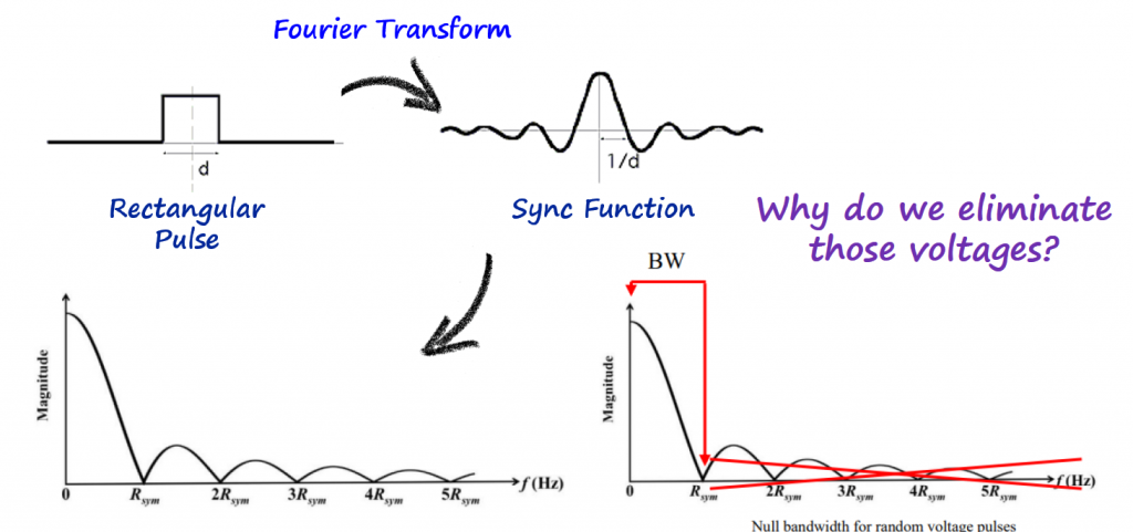
Sync Function
Don't be fooled on thinking that fl and fh are happening at the same time. What you see is the binary information signal changing faster than what we can do it manually. We have the effect of a square wave present when we switch between the space and mark symbols.
In other words, we are changing the carriers at the bit rate of the binary information signal, adding the effect of a rectangular pulse in time, which corresponds to a sync function in the frequency domain.
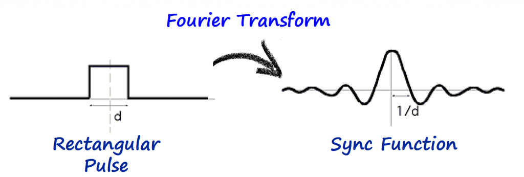
Wolfram website has a demonstration that illustrates the rectangular pulse and its Fourier transform.
The spectrum has all that information in it, where the sync function is present not only on the carrier and information signal carriers, but also on the Bessel sidebands.
BFSK
BFSK stands for Binary FSK, and it is very similar to the FSK scheme described above, but with a small difference.
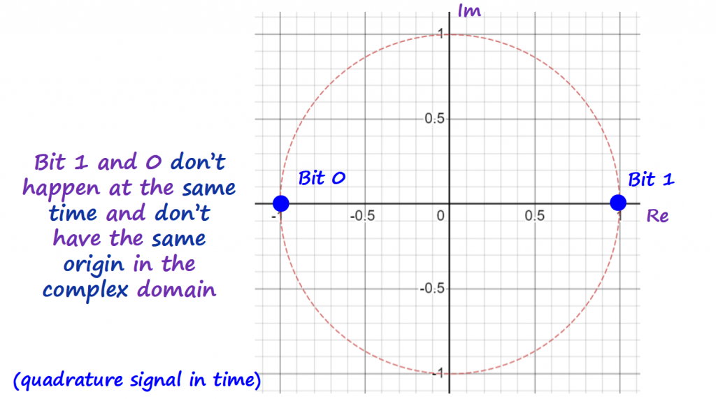
Since we are dealing with digital signals, it is now useful to start using constellation plots (introduce in the "IQ Plots/Constellations" section under the Fundamental Knowledge topic) to understand what is going on with symbols being transmitted.
The "Simple FSK Modulator with Bit Rate Control" is a good example to start with, but it will be very hard to demodulate or recover the information signal from it. The main reason is because the magnitude of the symbols carrier frequencies are the same, and in the complex domain the symbols will have the same origin. That leads to an intersymbol interference, meaning it is hard to distinguish when a 1 or 0 is transmitted.
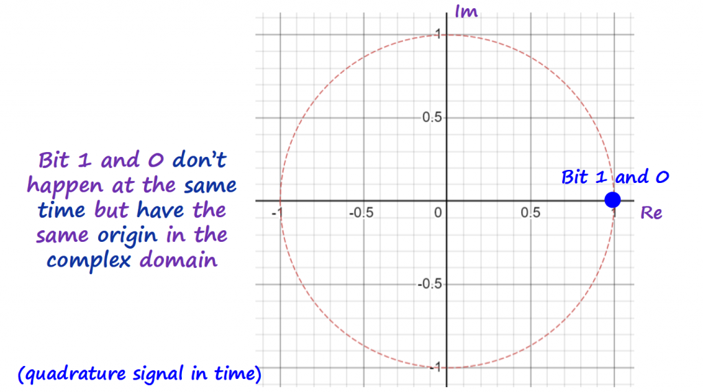
If we change the amplitude of the symbol carriers in way that set the symbols apart by 180 degrees in the complex plane, we are on the right direction to reduce considerably the intersymbol interference.
The conversion table is the following:
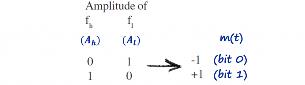
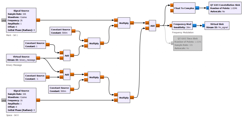
The block diagram is now adapted to reflect this amplitude change.
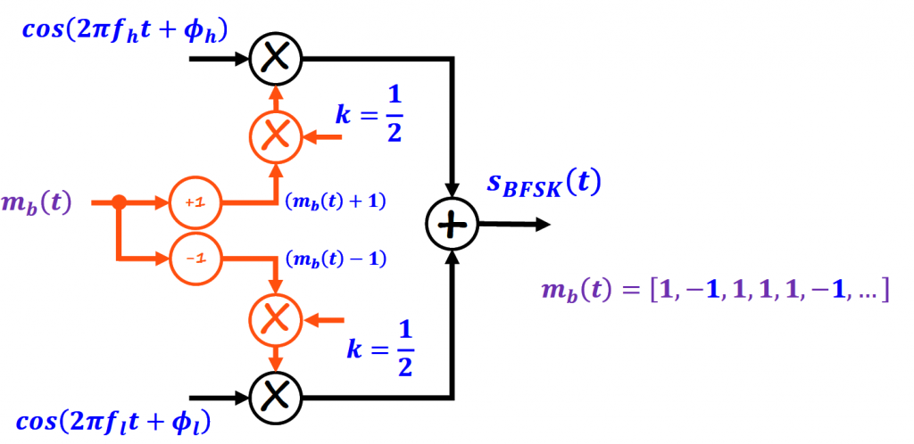
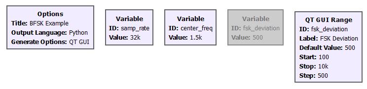
The GNURadio flowgraph for the BFSK is below.
Frequency Deviation
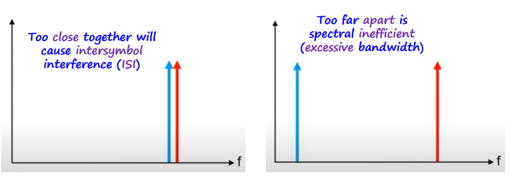
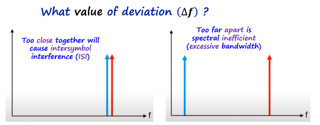
Δf is called frequency deviation and sets the distance between the two symbols used by the BFSK scheme. As you are probably already guessing, if this Δf is to small, the symbols will be too close from each other and that can cause what is called intersymbol interference, or in other words it can bring challenges to demodulating the signal. On the other hand, if Δf is to big, than it will be spectral inefficient, meaning it is using too much bandwidth.
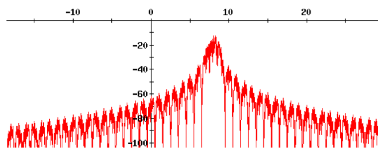
The image below shows the spectrum of a BFSK signal for different values of frequency deviations (Δf).
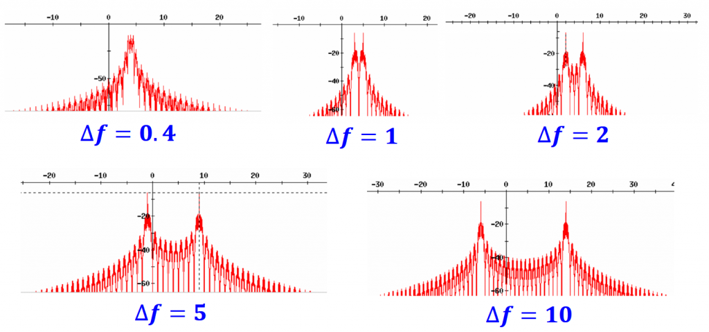
With these plots we can validate the importance of selecting the right Δf for your application. The sections below go over special cases of FSK for different Δf.
Sundes' FSK
Is a special case of the BFSK. The frequency spacing of the two carriers (fl and fh) is exactly equal to the symbol rate.
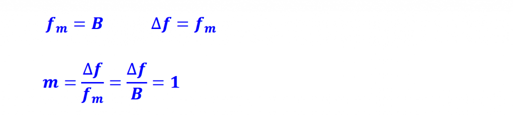
Two tones will appear at frequencies which are exactly the symbol rate and these help during the demodulation of this signal without external timing information. When you can extract timing information from a signal, the detection task is called coherent and generally has better Bit Error Rate (BER) performance. I will cover what BIT is on another article.
MSK
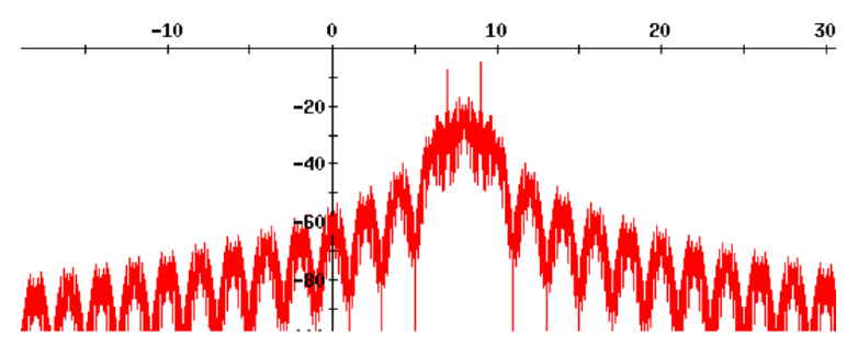
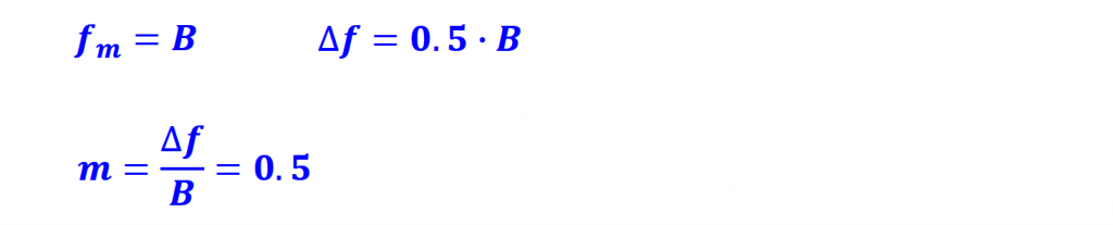
MSK is another special form of FSK also called Continuous Phase FSK (CPFSK). It is widely used in cellular systems. Δf is set to half of the Bit Rate.
Although MSK is often classified as FM modulation, it is also related to Offset-QPSK (I will cover this scheme under PSK Modulation section), owing to the dual nature of FSK and PSK modulations.
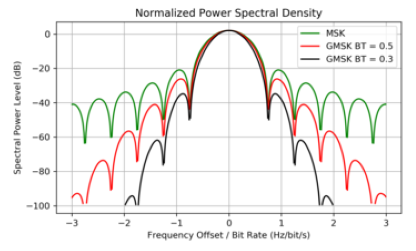
In MSK modulation scheme instead of using a rectangular pulse wave to switch between the carrier frequencies, a sine wave is used.
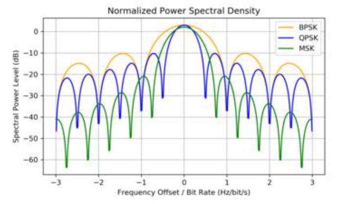
This scheme reduces sideband power, which in turn reduces out-of-band interference between signal carriers in adjacent frequency channels.
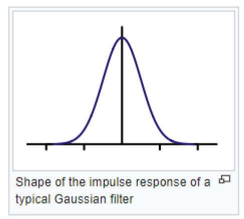
Gaussian MSK
It is similar to standard MSK. However, the digital data stream is first shaped with a Gaussian filter before being applied to a frequency modulator.
Offers better sideband power, and higher spectral efficiency.
On the other hand, it increases the modulation memory in the system and causes intersymbol interference. It also required more complex channel equalization algorithms such as an adaptive equalizer at the receiver.
GMSK is most notably used in the Global System for Mobile Communications (GSM), Bluetooth, satellite communications, and automatic identification system (AIS) for maritime navigation.
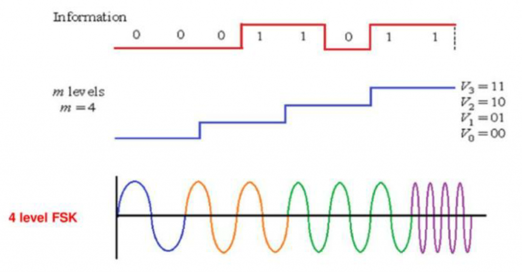
M-ary FSK
It is another extension of BFSK that allows more carriers to transmit more information at the same time. It is the same concepts described under M-ary ASK section but instead of splitting the amplitude into different levels, the split is done by using different frequencies called tones (M).
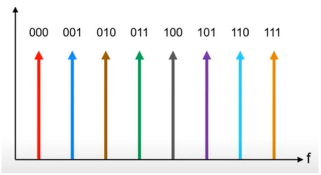
The number of tones (M) is always even: 4FSK, 6FSK, 8FSK, etc.., and each tone represents N = log2(M), where N is the number of bits. The example below represents a 4FSK modulated signal that uses 4 different symbol carrier frequencies.
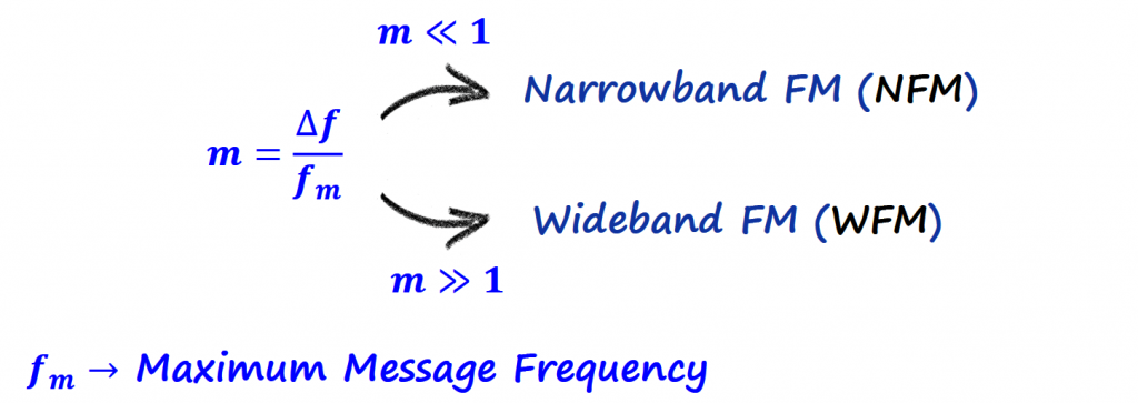
Modulation Index
The modulation index used for the analog FM ("NFM vs WFM" section) needs to be adjust for the modulation index used for the BFSK.
Since we are dealing with digital data, we need to find some information from the digital baseband signal.
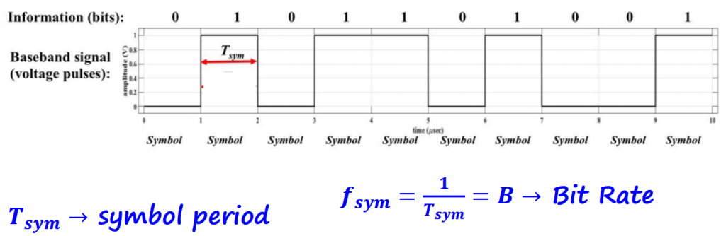
We can find a relationship between Nyquist and Bit Rate.
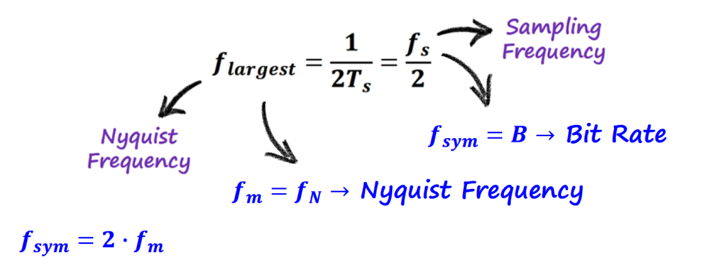
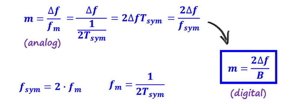
We can find the modulation index for the BFSK:
Bandwidth
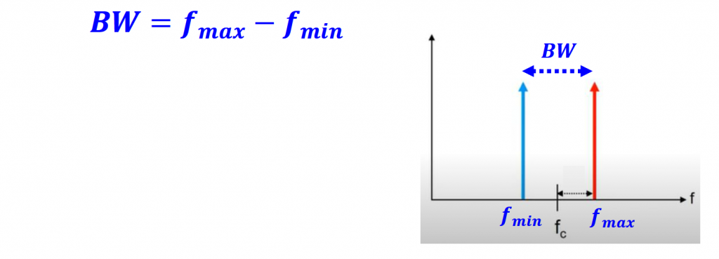
BFSK (or 2FSK) uses 2 frequencies: mark (logical 1) and space (logical 0). We know that the distance between the carriers and the nominal center frequency (fc) is called frequency deviation (Δf).
The question that you are probably asking since you start reading this article is, how far apart should the mark and space be?
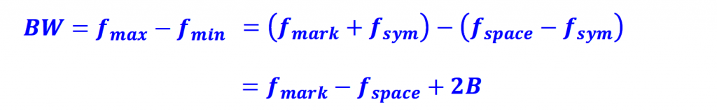
To find a possible answer to this question, let's see if we can find an expression for the bandwidth first taking into account only the mark and space frequencies.
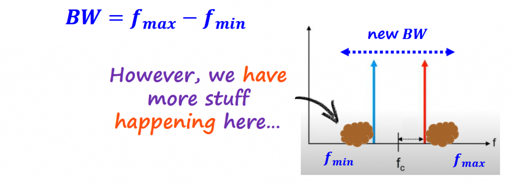
We know that we have more stuff going on with the spectrum. The fmin and fmax are going to be shifted according to additional spectrum content introduced by the Bessel functions (read the “Analog FM” section) and sync functions (read the "Sync Function" from the FSK Modulation section).
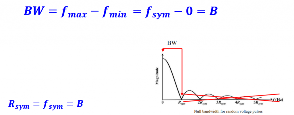
Sync Function
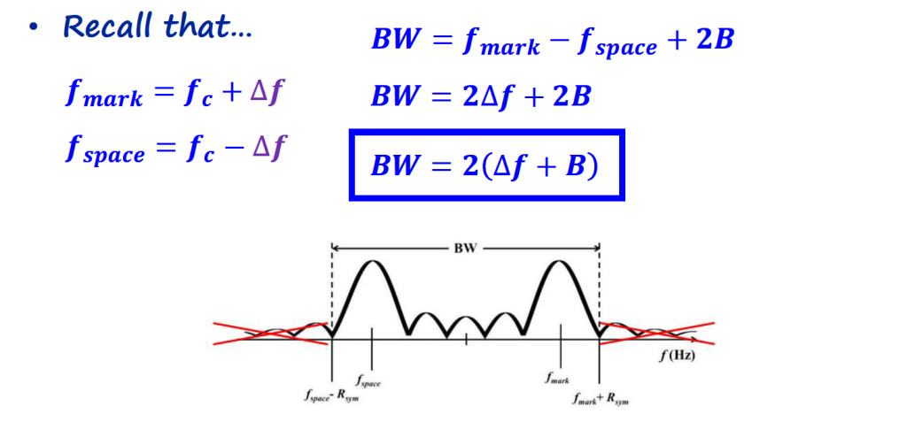
For now, let's consider only the effect of the sync function into the bandwidth calculation. For simplicity, we can eliminate all the lobes of the sync function after the Rsym .
With that, the bandwidth for the sync function is the following:
When the sync function gets shifted by the carrier, we adjust the bandwidth accordingly.
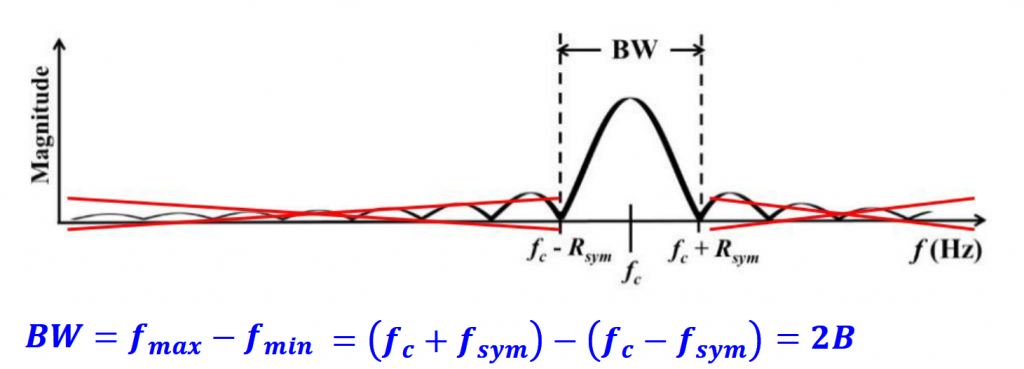
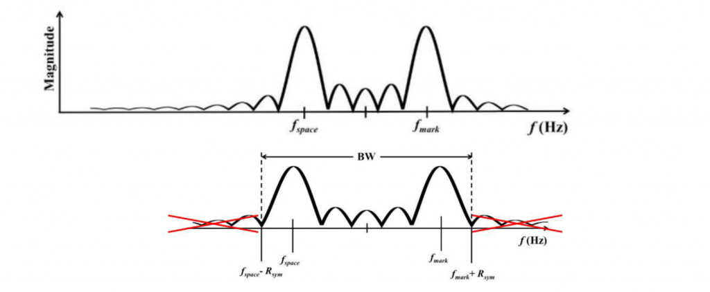
And putting the sync function, mark and space together:
Carson's Rule
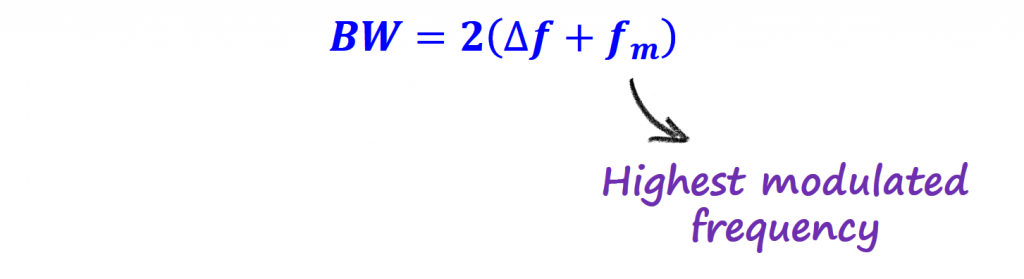
The equation from the previous section, is very similar to the bandwidth defined by Carson's rule used to calculate the bandwidth for analog signals.
Carson's rule defines the approximate minimum bandwidth requirements of communications system components by the equation below.
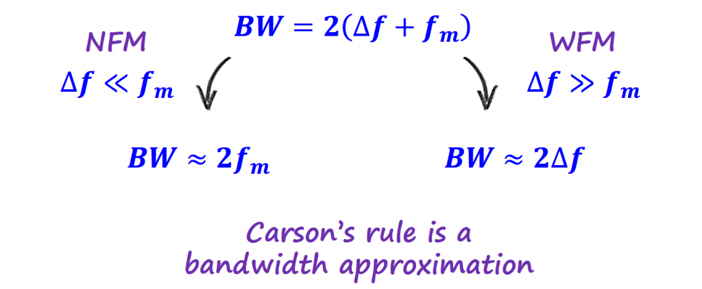
Carson's rule works well when the signal is analog, but it doesn't apply well when the signal contains discontinuities, such as square waves.
That tells us that the bandwidth found using only the sync function for a digital FM signal, can give some idea of the bandwidth but we need to find a better way if we want a more accurate answer.
Modulation Index and Bessel
A more accurate way to find the bandwidth for a digital FM signal is to look at the Bessel functions. We know that the Bessel functions are going to dictate the spectrum of the signal when using FM modulation.
The equation that governs the spectrum above is the following:
(review the "Analog FM" section for more details on how to get to this equation)
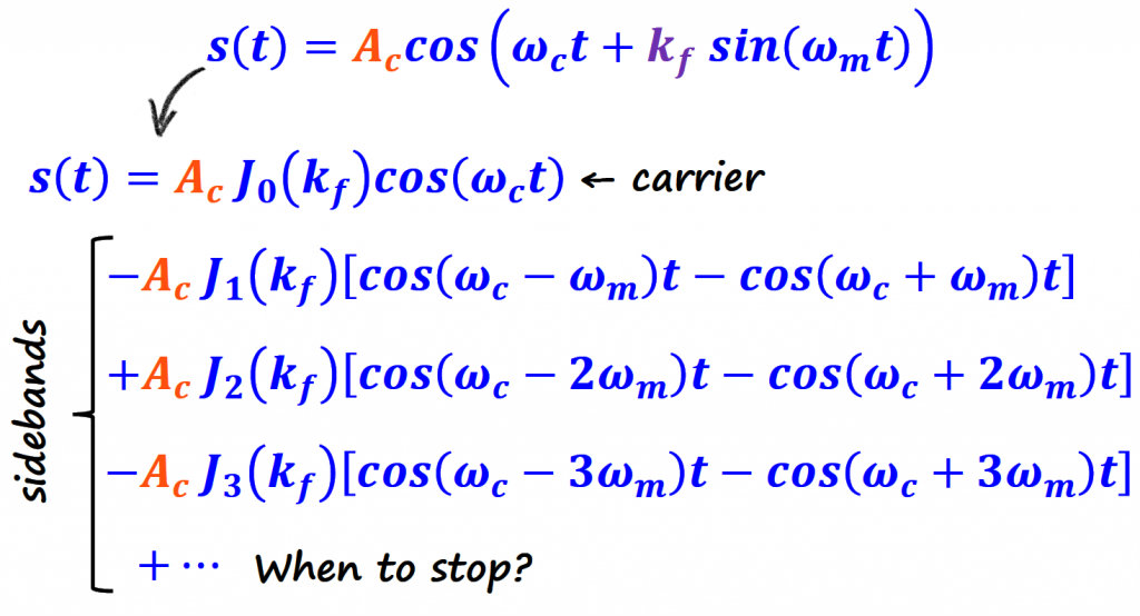
Bessel functions generate infinite sidebands, and the main question to define the bandwidth is how many of the sidebands should be considered.
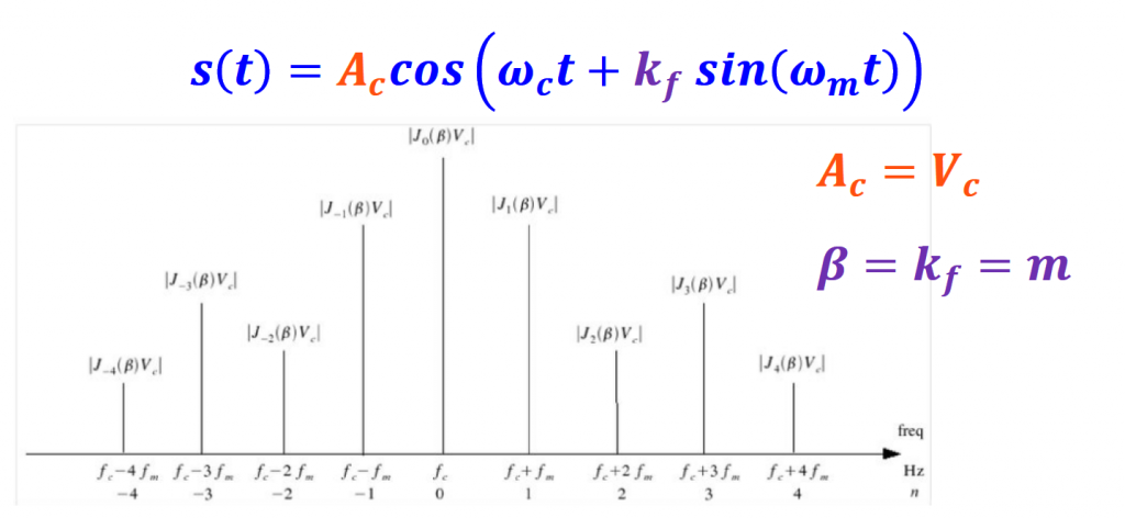
To find an answer to this question, we need to relate the modulation index with the Bessel functions.
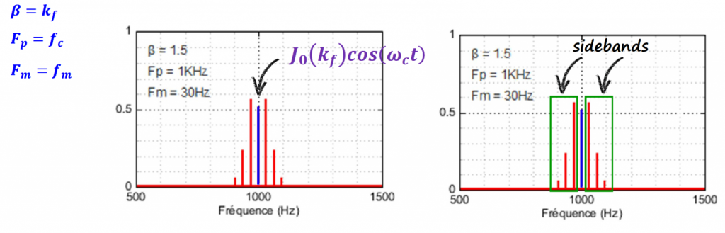
Let's relate the coefficients of the equation with some parameters in the spectrum.
If we look at the amplitudes of the Bessel functions, we notice that around the 4th function the Bessel functions amplitudes become insignificant (< 10% of Vc).
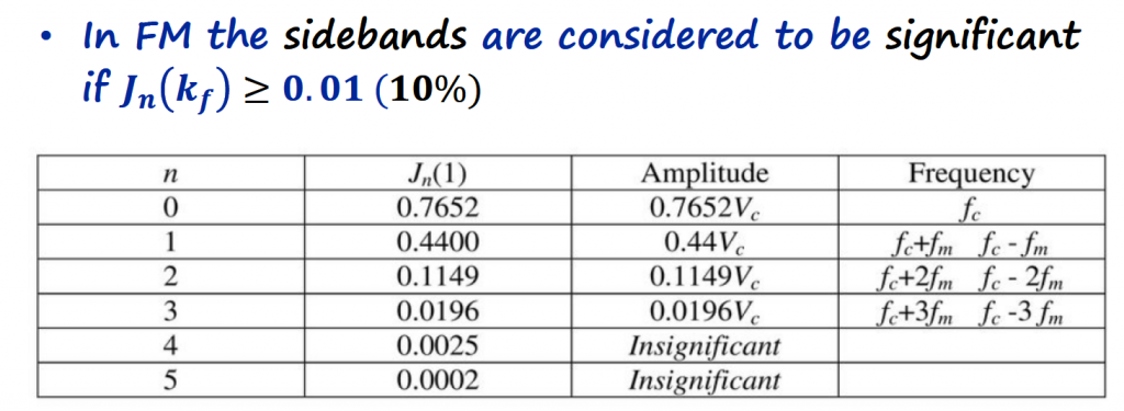
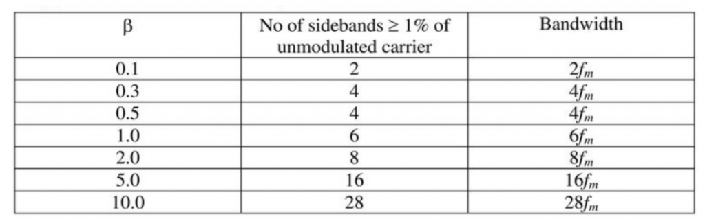
The table below can be used to find a more accurate representation of the bandwidth considering the modulation index (m=β) and the sidebands.
Example
To get a grasp on the equations that were presented above, let's go over a quick example. Let's find the bandwidth for VHF/FM (30 MHz - 300 MHz) radio transmissions in the band 88 MHz to 108 MHz with the following parameters:
fm = 15 kHz (e.g., music)
Δf = 75 kHz
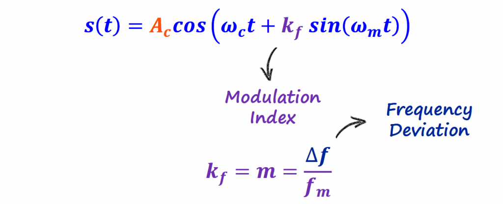
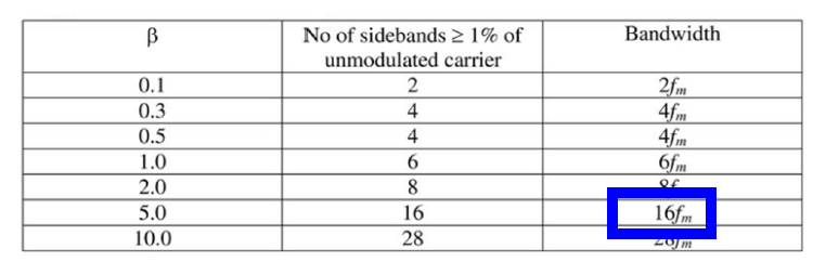
The modulation index for these parameters is m = Δf/fm = 5
The bandwidth using Carson's rule is:
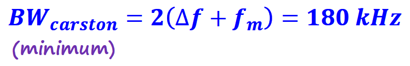
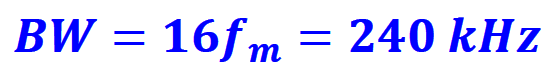
The bandwidth using the Bessel functions + modulation index:
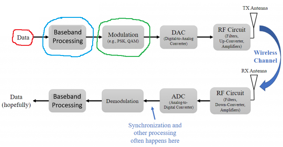
GNURadio Flowgraph <=> Tx-Rx Chain Block Diagram
We implemented FSK schemes with GNURadio flowgraphs, and this section goal is to relate some of these flowgraphs with the Tx-Rx Chain block diagram introduced in the Intro section of the Analog Data to Analog Signal topic.
Simple FSK Example
GNURadio Files
- Simple FSK Example
- Simple FSK with Bit Rate Control Example
- BFSK Example
References
- [Ref 1] “PySDR: A Guide to SDR and DSP using Python”, PySDR Website [Articles]
- [Ref 2] “Tutorial 17: Frequency Modulation (FM), FSK, MSK and more”, Complex to Real Website, Charan Langton [Article]
- [Ref 3] “Tutorials on Digital Communications”, Complex to Real Website, Charan Langton
- [Ref 4] “Summary of Trigonometric Identities”, Clark University [Article]
- [Ref 5] “Modern Digital and Analog Communication Systems”, B. P. Lathi and Zhi Ding [Book]