MCP4251
Digital Potentiometer
The MCP4251 is a digital potentiometer with a resistor network that can be controlled using SPI. This article explores on how to develop a driver in C that interacts with this component and how can you adjust the driver according to a microcontroller of your choice.
Introduction
The datasheet of the MCP4251 is a bit confusing to follow at first but let's go over it and get the important information in order to control it.
As always, I recommend you having the datasheet opened at the same time you read this article and follow along the pages that I will indicate throughout the article.
I got the MCP4251 - 10k Dual Potentiometer SOIC package
The block diagram on page 2 shows a bit more information of what is inside this IC.
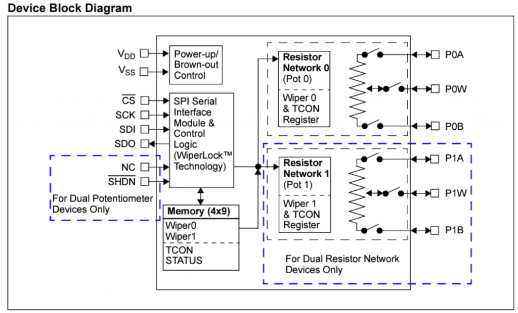
- I found this block diagram particularly useful because it shows the registers names that we will be interacting with when using the SPI commands.
- We can also see the pins that we need to interact with: the two resistor networks pins, the SPI pins, the power pins and the hardware shutdown pin.
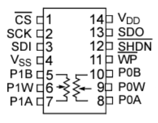
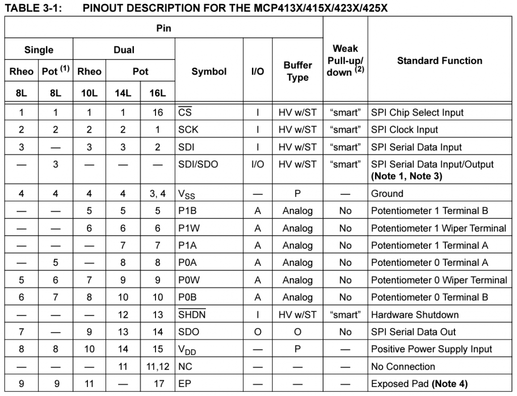
To get the pins description we need to go to Table 3-1 on page 31.
- The maximum supply voltage for this IC is 5.5V (Table on page 4) and it will be connected to pin 15 (VDD).
I think we have the necessary information for now to start connecting the MCP4251 to a microcontroller.
Hardware Connections
For simplicity, I am going to use an Arduino Uno to interact with the MCP4251. The connections are below.
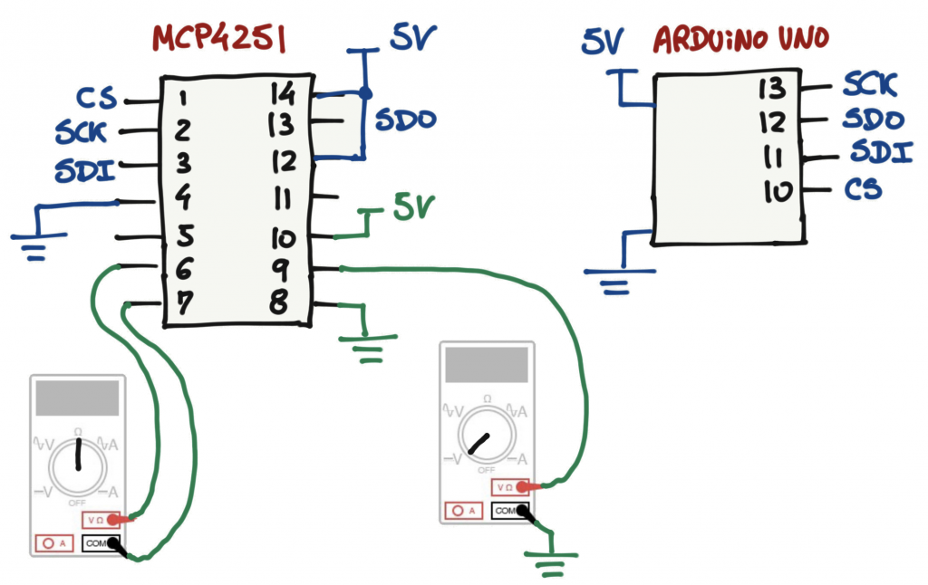
For some initial testing, I am going to set up Pot 0 as a voltage divider and measure the voltage across P0W (Pin 9) and I will also measure Pot 1 resistance between P1W and P1A (Pin 6 and 7 respectively). With these two tests I can see the voltage changing and the impedance changing for different resistor network settings.
Software
Let's go over the code to interface the MCP4251.
SPI
For the SPI code, I will be using the standard SPI library for the Arduino Uno:
- SPI.begin
- SPI.transfer
Under section 7.0 - Device Commands (page 4), the MCP4251 supports 16 memory address locations and 4 commands.
On Table 7-1, we can see that 2 commands are 16 bits long and the other 2 commands are 8 bits long.
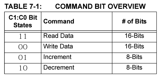
The general SPI command formats are under Figure 7-1. Notice that the command bits from Table 7-1 are bit 2 and 3 from the Command Byte.
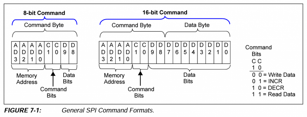
With this in mind, we can write two functions that send commands and data bytes.
Note: For this particular device, the CS pin allows you to control the device into two additional sub-modes: normal serial commands (CS pin is driven to LOW), and high-voltage serial commands (CS pin is driven HIGH).
void command_8Bit(uint8_t cmd){
  digitalWrite(CS_PIN, LOW);
  SPI.transfer(cmd);
  digitalWrite(CS_PIN, HIGH);
}

void command_16Bit(uint8_t cmd, uint8_t data){
  digitalWrite(CS_PIN, LOW);
  SPI.transfer(cmd);
  SPI.transfer(data);
  digitalWrite(CS_PIN, HIGH);
}
From the SPI point of view, that is it. Now we just need to start constructing the commands and data fields according to what we want to do with the MCP4251.
Commands
The commands are summarized on Table 7-2 (page 48).
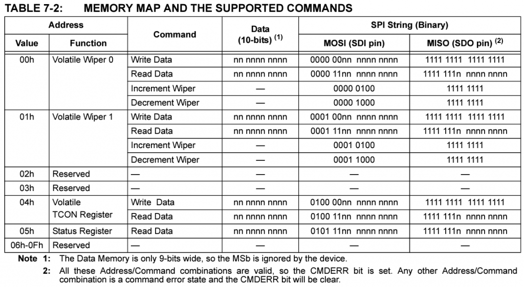
The 4 MSB bits of the command Byte (from Figure 7-1) are going to hold the memory address value.
For example, if we want to set Pot 0 at 50% we will send the following SPI command and data Byte:
- Command Byte: b0000 00xx (0x00)
- Data Byte: b0001 0000 (0x80)
I will give another example, set Pot 1 at 75% (192/256):
- Command Byte: b0001 00xx (0x10)
- Data Byte: b1100 0000 (0xC0)
Simple Arduino Code
With this information we can build a simple test to control Pot 0 and Pot 1.
#include <SPI.h>

// Volatile Memory (RAM)
#define MCP4251_WIPER_0_WRITE_ADD   0x00
#define MCP4251_WIPER_1_WRITE_ADD   0x10

#define CS_PIN  10

void setup() {

  // initialize SPI:
  SPI.begin();

  // Configure Pot
  command_16Bit(MCP4251_WIPER_0_WRITE_ADD, 0); // wiper values from 0 to 255
  command_16Bit(MCP4251_WIPER_1_WRITE_ADD, 192); // wiper values from 0 to 255
}

void loop() {
}

void command_8Bit(uint8_t cmd){
  digitalWrite(CS_PIN, LOW);
  SPI.transfer(cmd);
  digitalWrite(CS_PIN, HIGH);
}

void command_16Bit(uint8_t cmd, uint8_t data){
  digitalWrite(CS_PIN, LOW);
  SPI.transfer(cmd);
  SPI.transfer(data);
  digitalWrite(CS_PIN, HIGH);
}
Driver
soon...
GitHub Code
References
- [REF 1] "MCP4251 1/8-Bit Single/Dual SPI Digital Pot with Volatile Memory", Microchip [Datasheet]