ESP8266 Part 5
UDP CLIENT + SERIAL COM
The ESP8266 has the ability to interact with peripherals and send information over a WiFi connection to remote computers or devices. However, it can also be used to enable other microprocessors to have access to networks and send/receive information over WiFi.
The goal with this article is to show how you can use the ESP8266 as a network shield to be used by any microprocessor that has UART communication capability. This example can be used to transmit data being acquired by the ESP8266 serial port to a remote UDP server. Have in mind that you might lose data during transmission. If your application cannot afford to lose packets or data, you should use a different approach (for example a TCP connection).
Below you can find the block diagram of the system that we will be using in this article.
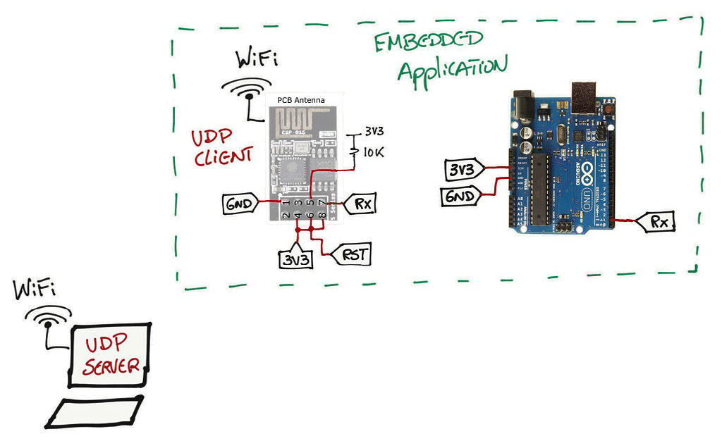
It consists of an Arduino UNO board that will be sending the value of a counter at a certain rate over a serial port to the ESP8266 board. On the other end, the ESP8266 will forward any message received on the serial port and forward it over a UDP socket to a remote server.
To program the ESP8266, follow Part 1a (if you want to use the Arduino UNO board) or Part 1b (if you want to use the serial-USB interface) to program the board.
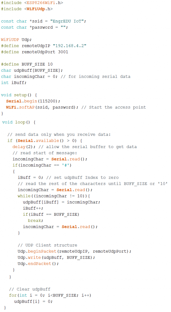
ESP8266 UDP Client
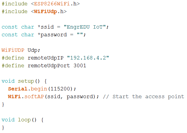
As always let's start from the beginning and have an Access Point and a UDP client socket ready to be used. You can find more details about this portion of the code in Part 3 of this series of articles.
Now we need to include the code in the main loop that will deal with the incoming data from the ESP8266 serial port. This part requires several steps until we have something working properly. The way that I am going to approach this section is by providing a flow chart that shows how the code is working.
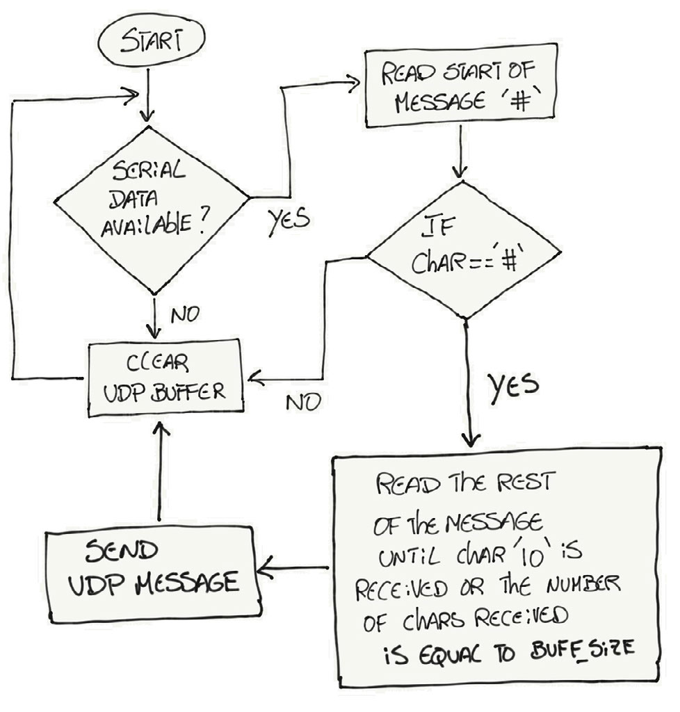
If you are familiar with reading flow charts and you can understand what is going on, you can skip the section below and go directly to the code portion of the flow chart. If you are not familiar with flow charts, I will guide through this one so you can understand how the code is working.
Flow Chart Explanation
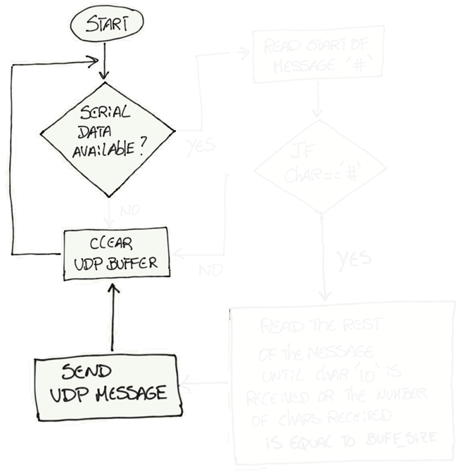
We start by waiting for data to come on the serial port. If data is not available, we are going to clear a buffer that will be used to fill with information that will be sent over the UDP client socket later. We are clearing the buffer to make sure that we only include the data that we want to send over the socket.
If data is available on the serial port, at this point it is important to start collecting all the characters that are being sent by the Arduino UNO before we send that message over the UDP client socket. However, it is important to synchronize the message that is being sent by the Arduino UNO and the message being received by the ESP8266. The synchronization strategy here is similar to the one used with GPS modules and NMEA messages. All NMEA messages start with the $ character, but in our example we will be using the # character to start any message sent by the Arduino UNO. If the character received by the serial port is not the # character, the code will keep looping from the beginning.
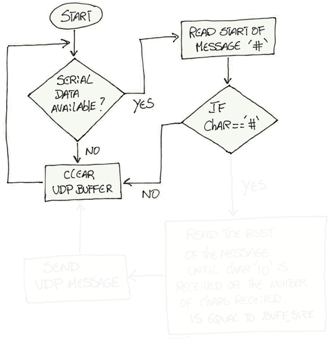
As soon as a # character is received, we enter a new state of collecting all the characters that belong to a message. Going back to the GPS NMEA message example, NMEA messages have a predefined structure where messages start with the $ character and then each data field is separated by a comma. You also know how many data fields are present in each NMEA message. In our case, things are bit more simple. We don't have too much going on so we are going to define the end of our message if we received the line feed character '\10' or if we receive a total of bytes equal to BUFF_SIZE.
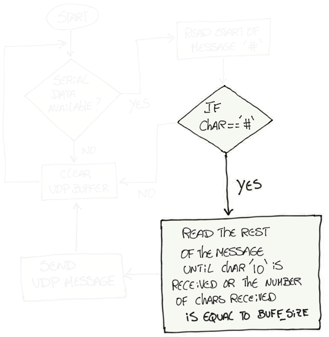
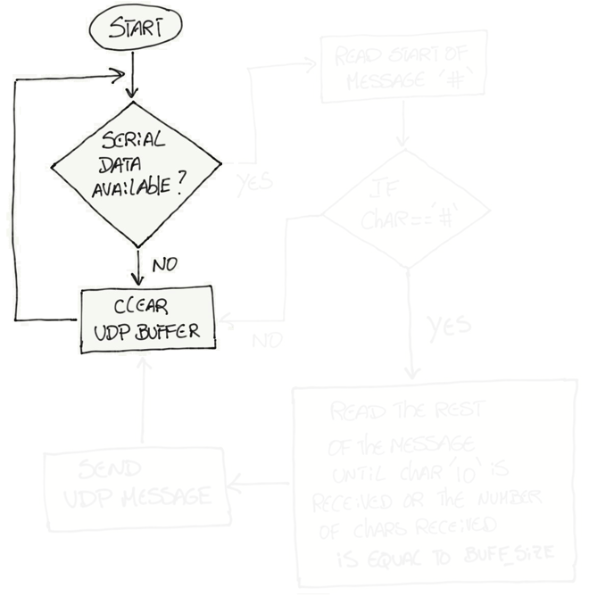
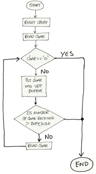
The block that is responsible to read the rest of the message can be explained with a second flow chart. The reason why this second flow chart was not included on the first flow chart is to make things easier to follow and read.
On this sub flow chart, we start by reading the next character after the # character. If that character is different than the line feed character, we will store that character on the UPD buffer. We then check if we received more characters than BUFF_SIZE, if not, we repeat the cycle and keep receiving and storing characters until either we receive the line feed character or we receive as many bytes as BUFF_SIZE.
At last we are ready to send the data that we collected trough the serial port over the UDP client socket. We clear the buffer again before we start a new collection of data coming from the serial port.
Full UDP Client Code
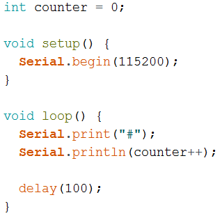
Arduino UNO Serial Code
The code from the Arduino UNO side is sending the beginning of a message, the # character, the respective counter value and the line feed character to terminate the message is included on the println statement. Make sure that the serial baudrates are the same for both the ESP8266 and the Arduino UNO. In this case is 115200 bps.
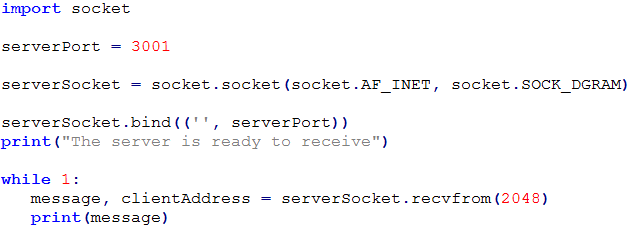
UDP Server (in Python)
Writing python code, specially code for network communications (UDP and TCP sockets) is outside of the scope of this article. It can be complex to develop a UDP server that handles a variety of different protocols and is robust to protocols or connections issues. However, below you can find a simple UDP server that you can use to test with the ESP8266 UDP client. Have in mind that you should change this code in order to be more tolerant to protocol or connection issues.
A couple of things to have in mind:
- Make sure that your computer is connected to the same WiFi network that you created with the ESP8266 (in this example EngrEDU IoT).
- Check the IP address that was assigned to the device that is being used as the server (computer or raspberry pi). In this example is "192.168.4.2"
- Use that server IP address in your remoteUdpIP variable(in your ESP8266 code).
- Use the same serverPort number (python code) as the number under remoteUdpPort (in your ESP8266 code) - in this case 3001.
- On windows computers you might need to configure your firewall to allow UDP communications to happen under that UDP port.
This should be sufficient to see some action happening. Now all you need to do is to focus on the protocol that you want to use for your application. Instead of sending the counter value, you can send whatever data you would like to.
Note: On AVR based boards, outgoing UDP packets are limited to 72 bytes in size currently. For non-AVR boards the limit is 1446 bytes [Reference].