ESP8266 Part 1b
SERIAL-USB PROGRAMMING
The goal with this article is to show how to write and deploy code on the ESP8266 module using a serial-USB interface. We will be uploading a simple blink LED program.
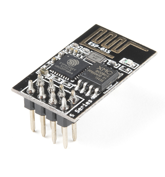
The ESP8266 module used is from sparkfun. In a nutshell "The ESP8266 WiFi Module is a self contained SOC with integrated TCP/IP protocol stack that can give any microcontroller access to your WiFi network. The ESP8266 is capable of either hosting an application or offloading all WiFi networking functions from another application processor."
HARDWARE
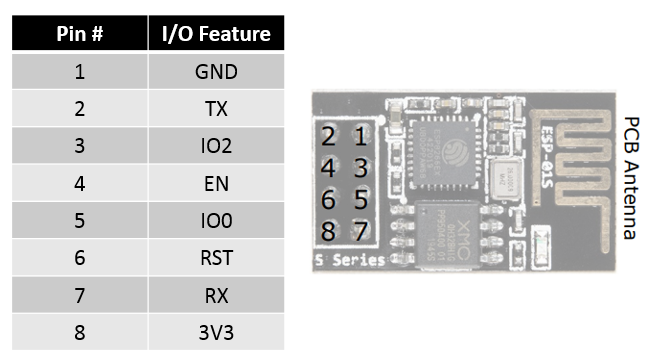
ESP8266 Pinout
Connecting the ESP8266 with a Serial-USB
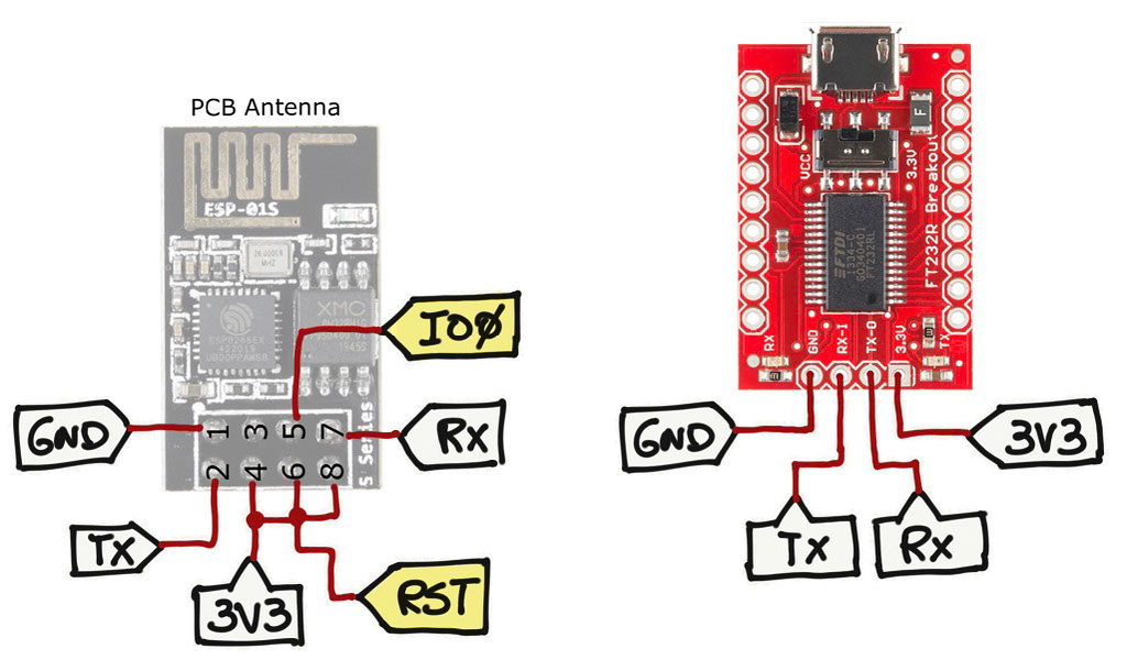
Connect the TX with RXand RX with TX. The pins IO0 and RST are in yellow to indicate that we will need to move them around to switch between programming mode and normal operation mode (more about this below). For now, you can leave the RST pin connected to 3.3V and IO0 floating (not connected).
That is all for the hardware. Now let's go over the software side of the ESP8266.
SOFTWARE
Install the ESP8266 Library on Arduino IDE
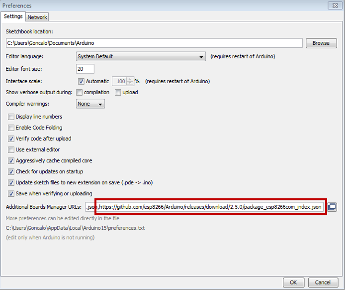
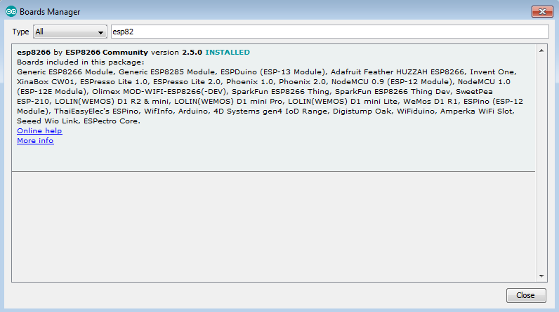
For some odd reason I was only able to make the code work with the ESP8266 library 2.5.0 version. To include that version to your Arduino Environment, add the json library below in your "File -> Preferences -> Settings" - "Additional Boards Manager URLs"
json library:
https://github.com/esp8266/Arduino/releases/download/2.5.0/package_esp8266com_index.json
Then go to "Tools -> Board: -> Boards Manager..." and install the ESP8266 2.5.0 library
Compile Code for the ESP8266
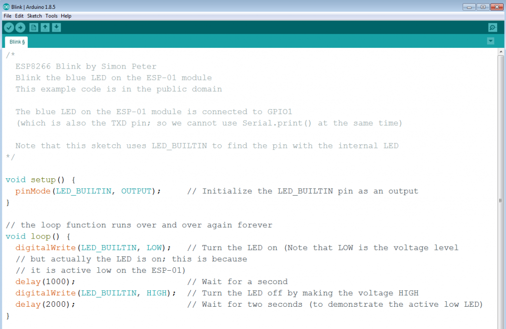
Go to "File -> Examples -> ESP8266 -> Blink". That should open the code below. It is a simple blink LED program that we are going to program the ESP8266 with to make sure that things are working properly.
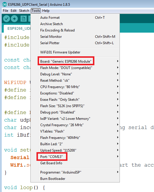
Before compiling the code, we need to select the correct platform. Go to "Tools" and pick the "Generic ESP8266 Module" for your board. Make sure that you also connect your Arduino board to your computer and select the respective COM port for your board. Example below.
You should be able to compile your code without problems.
Upload the Code Procedure
To upload the code to the board we need to perform some operations on the yellow pins (IO0 and RST) stated in wiring diagram section.
Before you press the button to upload the code, make sure that you connect IO0 pin to ground and the RST pin to 3.3V.
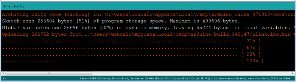
Press the upload button, and when the word uploading shows up on your console, the ESP8266 module needs to be in programming mode.
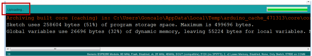
To switch the ESP8266 to programming mode, move the RST wire to ground and back to 3.3V. That will put the ESP8266 in programming mode. The blue LED on the board will start flashing as the board gets programmed and you can track the progress on the Arduino IDE console.
After the upload is done, disconnect the IO0 pin from ground (you can leave it floating) in order for ESP8266 to enter the normal operation mode and run the code that we just uploaded.
That is it, this is the procedure that you need to do all the time that you want to deploy any code to the ESP8266 using a serial-USB interface.
Part 2 will cover on how to setup your own network as an Access Point with ESP8266.