LTSpice Switches
LTSpice Switches
Simulating switches are relevant if you want for example to study/simulate the transient of an RLC circuit, or if you want to simulate switching capacitors circuits, or a button for user input.
LTSpice Switches
There are several different types of switches [Ref 2], but for this article, we are going to focus on the simple switch.

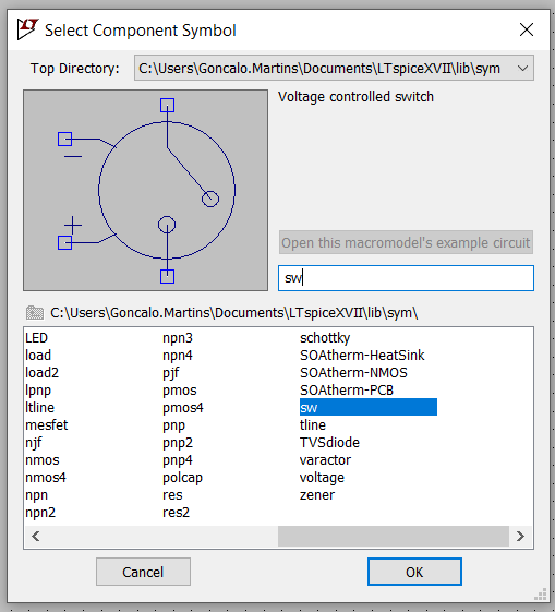
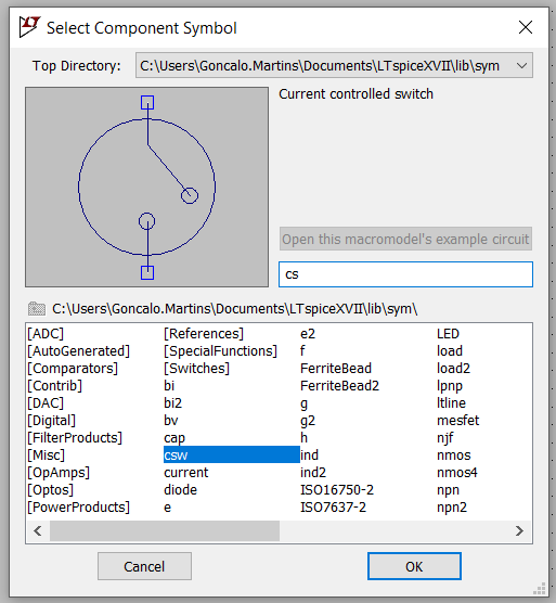
In LTSpice the simple switch has two variations: a voltage controlled switch ("sw") and a current controlled switch ("csw").
SW -> Voltage Controlled Switch
The positive and negative terminals are used to control the opening and closing of the switch using a voltage source.
CSW -> Current Controlled Switch
The current through the named voltage source controls the switch's impedance.
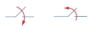
SW -> Opening & Closing Switches
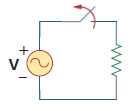
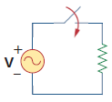
Traditionally in circuits exercises, the switch has an arrow on top of it to indicate the direction of movement.
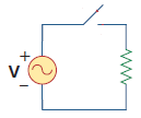
Let's use the circuit below that consists of a sine wave, a resistor and a switch. Depending on the movement of the switch, we either see a sine wave at the terminals of the resistor or not.
Close -> Open Simulation
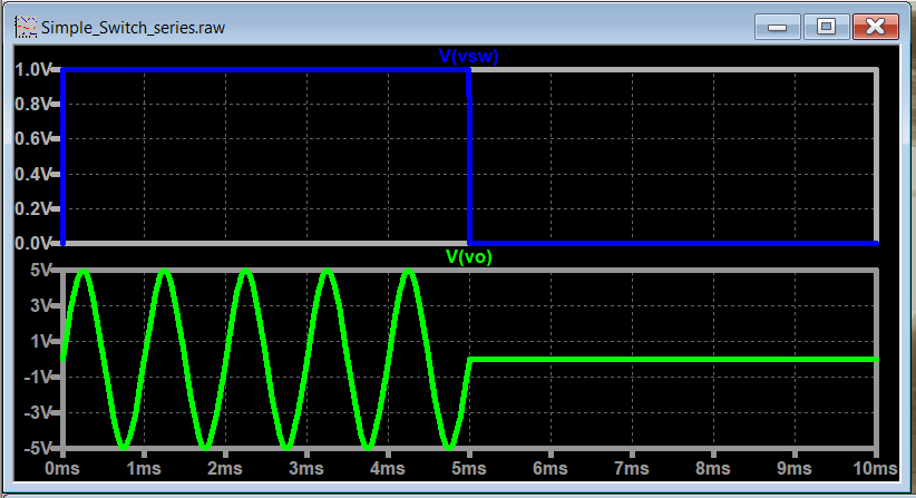
Let's simulate the circuit going from closed to open.
Notice that the circuit implementation is pretty straightforward. All you need to do is to substitute the switch with an "sw" component.
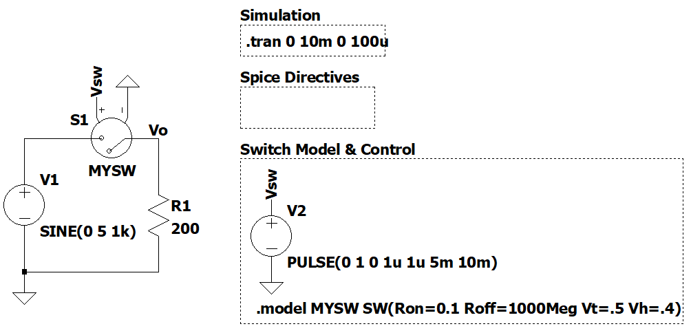
The switch behavior and timing characteristics are implemented under the "Switch Model & Control" box.
- The model of the switch is done by adding a ".model" spice directive. The switch has the same name as the model name.
- The control of the switch is done with a pulse waveform.
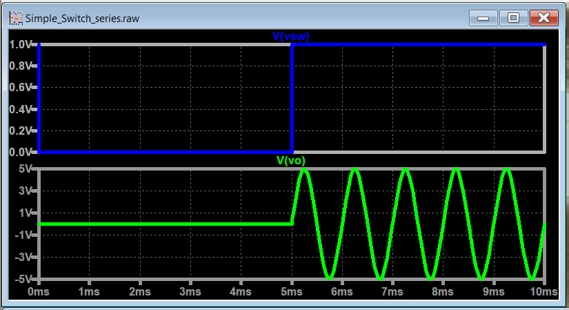
Open -> Close Simulation
Let's simulate the circuit going from open to close.
The only change that needs to be made, compared with the previous example, is on the switch behavior signal that is controlled by the pulse waveform.

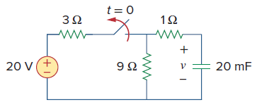
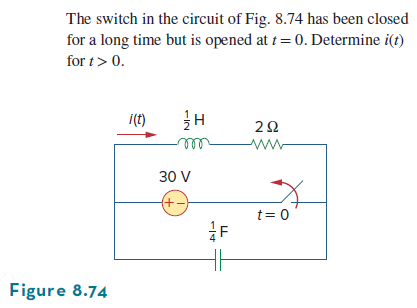
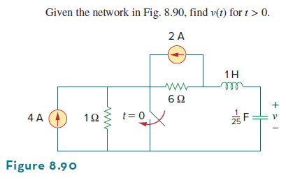
RLC Transient Circuits
Now let's focus on simulating transient circuits. For the circuit below, the switch starts closed and ends up open after a period of time. "t=0" means that you start doing the transient analysis at that point in time. "t<0" is related with setting the initial conditions of your circuit.
Option 1: We can simulate the circuit to reflect t<0 (set the initial condition in the circuit by simulation) and t=0 (transient). In this case, we need to include the LTSpice switch.
Option 2: We can simulate the circuit just for t=0 (transient) and include the initial conditions of the energy elements in the circuit by hand. In this case, there is no need to include the LTSpice switch.
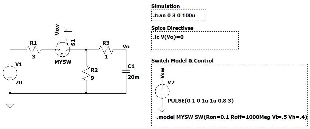
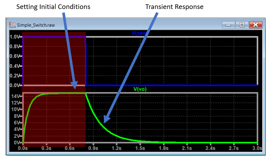
Option 1 -> t<0 & t=0
We build the circuit in LTSpice the same way as before, substitute the switch by the "sw" component and adjust the pulse wave and transient analysis timing accordingly.
Note: make sure that you leave the switch on for enough time to charge the capacitor completely before opening the switch.
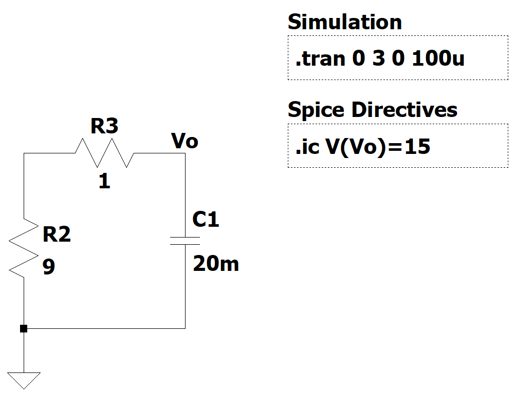
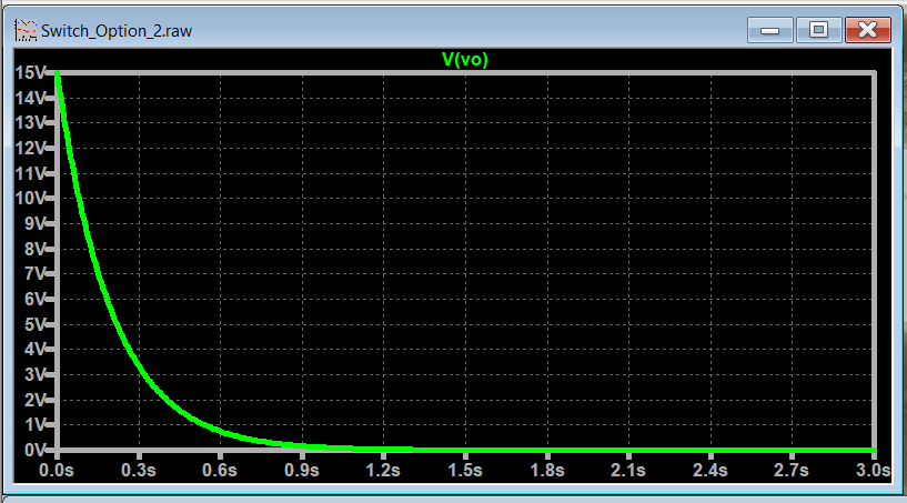
Option 2 -> t=0
To simulate the circuit only for "t=0", you need to know the initial conditions of your energy elements before hand. In this case, the capacitor is charged to 15V initially before opening the switch.
With that, we can redesign the circuit with the elements that are part of the transient and include the initial conditions as a Spice directive.
Switching Capacitors (Soon...)
Other Examples
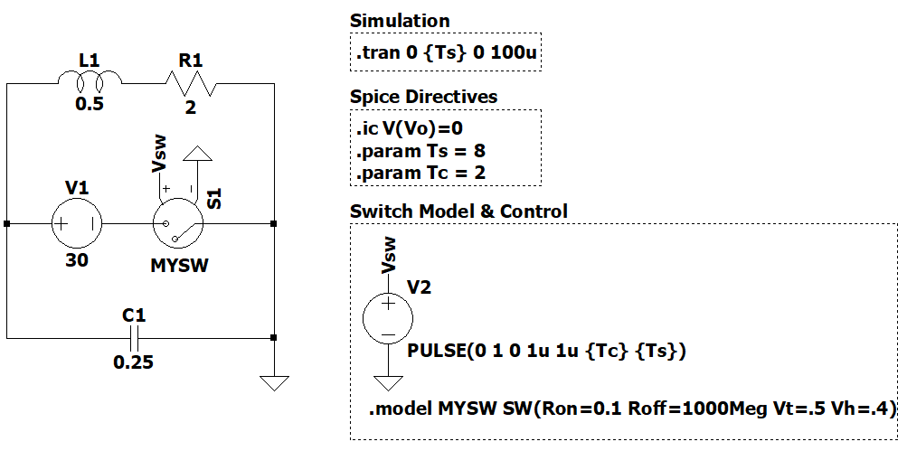
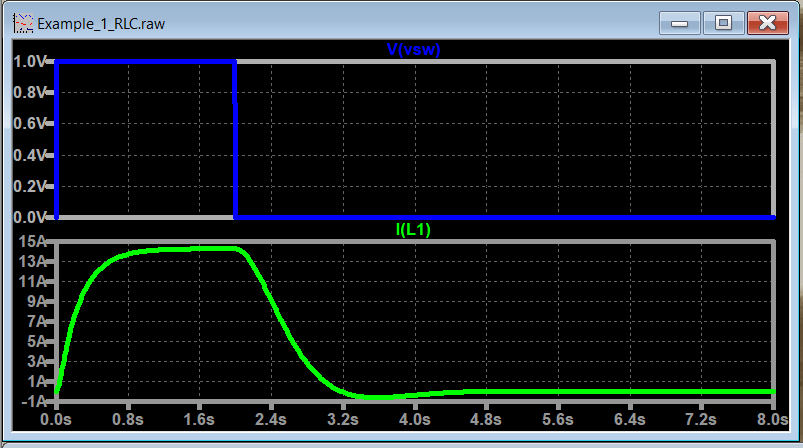
Example 1 (RLC)
We added two variable parameters, Ts (simulation stop time) and Tc (time the switch is closed) to make it easier to adjust the pulse waveform and simulation timings.
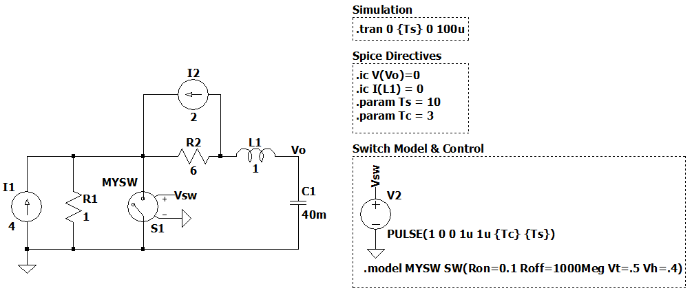
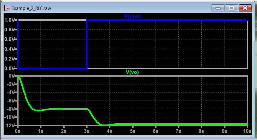
Example 2 (RLC)
We added two variable parameters, Ts (simulation stop time) and Tc (time the switch is closed) to make it easier to adjust the pulse waveform and simulation timings.
LTSpice Simulation Files
References
- [Ref 1] "LTspice: Voltage Controlled Switches", Analog Devices [Article]
- [Ref 2] "All Types of Electrical and Electronic Switch Symbol", ETechnoG [Article]