LTSpice Variable Resistor
Variable Resistor
LTSpice doesn't have a variable resistor (or potentiometer) symbol by default. However, we can use variable parameters to implement variable resistors.
Note: You can get familiar or review variable parameters here.
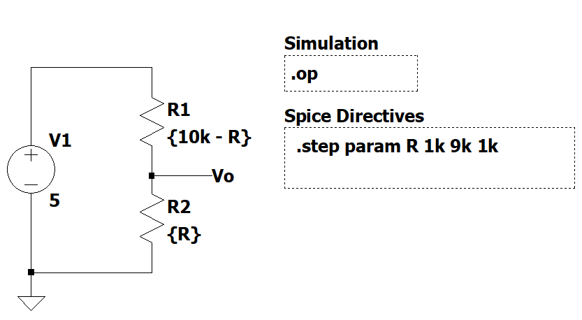
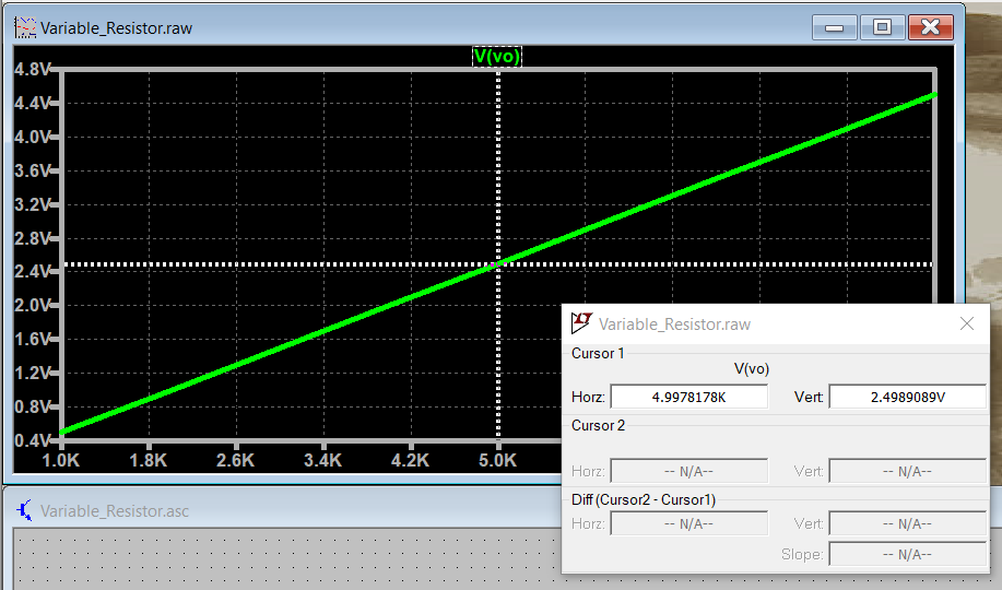
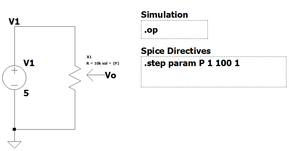
Let's build a simple example that shows the concept. We can have two resistors with variable names and relate the values between them to make a variable resistor. This is modeling a linear variable resistor or linear potentiometer.
It will be convenient for later circuits if we could improve this simple model to include the total resistance of the potentiometer and set the position of the potentiometer by means of a percentage.
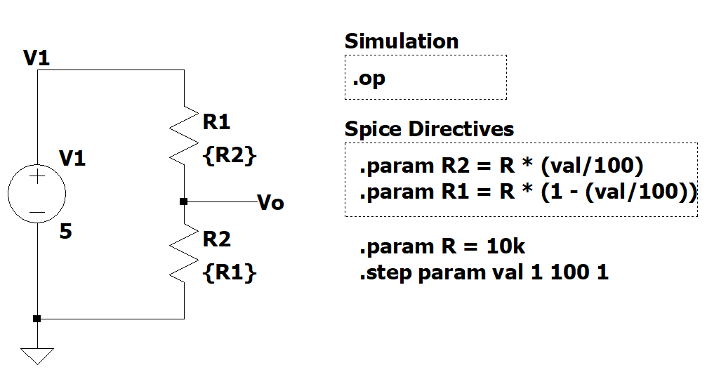
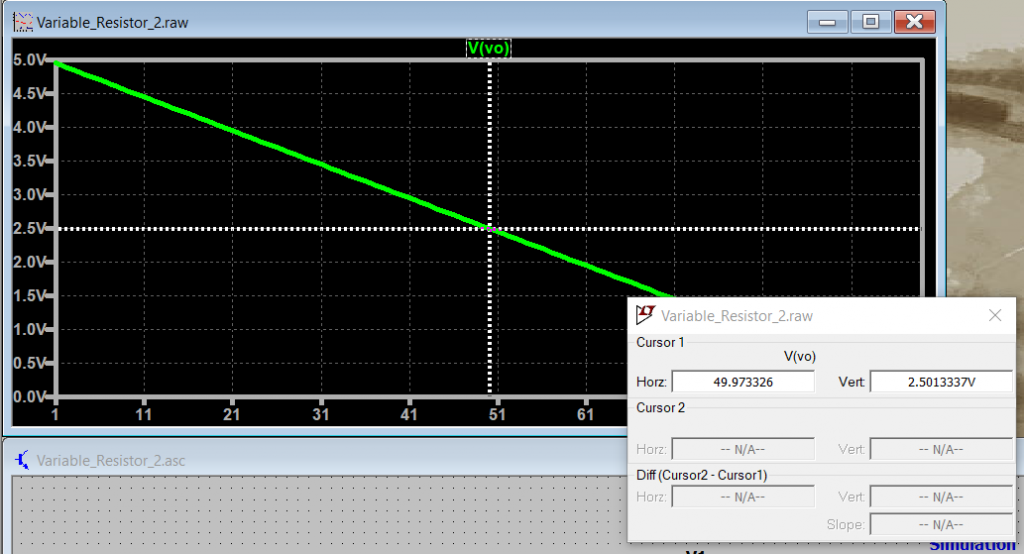
With this new model, we can set the total value of the potentiometer by changing R and change the potentiometer position using the val variable.
Potentiometer Example
If your schematic requires a hand full of variable resistors, it starts to become hard to manage the schematic overall. With that, we can create a symbol for this component and use the new symbol in your schematic.
Note: You can follow [Ref 1] that shows the steps on how to create the symbol for the improved variable resistor shown above.
You can also download the symbol and component and use it in your schematics right away. The easiest way to use this new component, is to copy the pot.asc and pot.asy file into the same working directory where you have your schematic. Then, when you are selecting a new component, go to the top directory menu and point to your working director and you should be able to see the pot component.
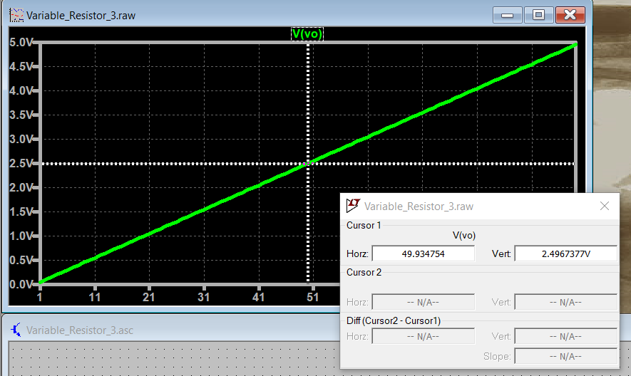
Now we can create our simple potentiometer circuit and test the output voltage for different percentages values.
Other Examples
Example 1
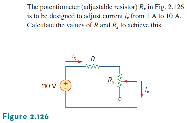
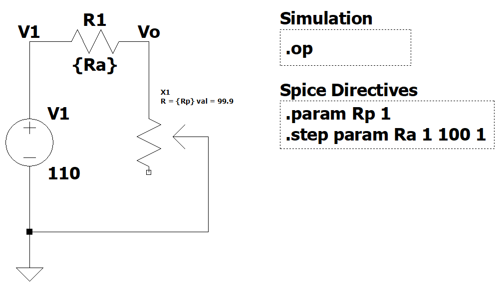
We have two components in series, and we want the potentiometer to control the current in the circuit from 1A to 10A.
- When the potentiometer is all the way up (100%) we have less total resistance, and we will have the maximum current flowing in the circuit - 10A.
- When the potentiometer is all the way down (0%) we have more total resistance, and we will have the minimum current flowing in the circuit - 1A.
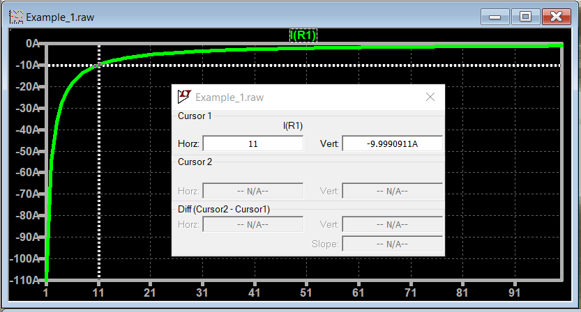
Let's start by setting the potentiometer at 99.9%, vary the value of R1 between 1Ω to 100Ω in steps of 1Ω and find the value of R1 that gives a current of 10A. We don't want the value of the potentiometer Rx to influence the amount of current that flows in the circuit. For that, we select a small value of Rx = 1Ω
Note: If you set the percentage parameter (val) of the potentiometer to 100% or 0%, LTSpice will give you an error because he can't compute values for the internal R's = 0Ω. To work around that limitation, you can set val to 99.9% or 0.1% respectively.
The next step is to vary Rx and find the value that gives a current of 1A when the potentiometer is set to 0%, and R1 = 11Ω.
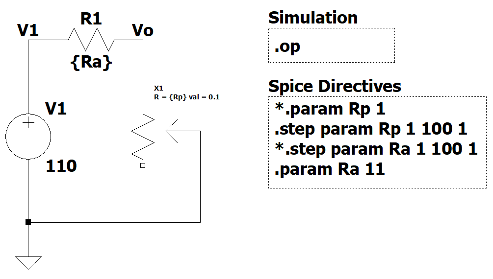
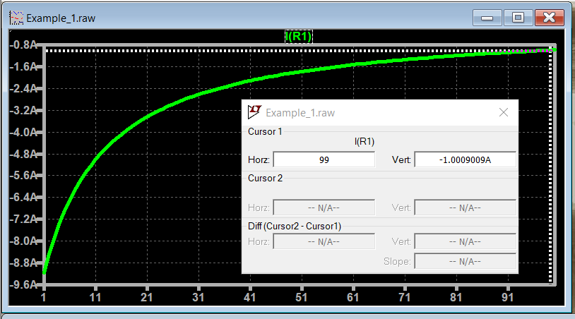
Answer: R1 = 11Ω and Rx = 99Ω
LTSpice Simulation Files
Potentiometer LTSpice Component
Directions: Download both files and place them in the same project folder that you are working.
References
- [Ref 1] "Potentiometer Symbol in LTSpice", Asa Pro YouTube Channel [Video]