H-Bridge DC Motor Driver
H-Bridge DC Motor Driver
Let's improve the basic motor driver and build a circuit that allows to control the direction of the motor.
Requirements
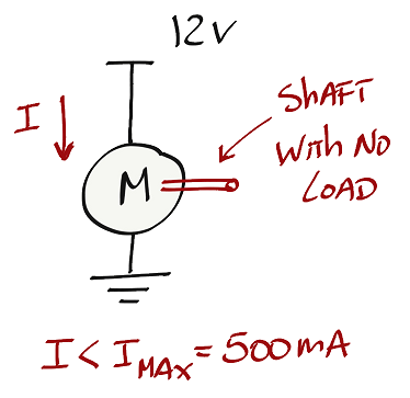
The motor that we will be controlling can handle 12V and a maximum current (Imax) of 500 mA.
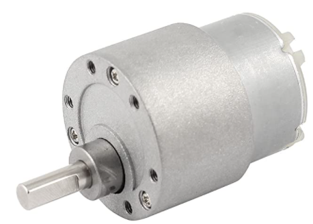
If we connect the motor directly to a power supply and apply 12V and if there is no load on the shaft, the motor will run freely with a current less than Imax.
With this configuration we are not able to control the motor with a microcontroller. We need to include some sort of switch that allows to turn on and off the current that flows through the motor.
Transistors are good candidates to be used as switches to control the current that flows through the motor. There are different types of transistors but we will focus on using MOSFETs for this motor driver.
H-Bridge with MOSFET
Design
In order to control the direction of a motor I need to find a way to change the direction of the current that flows through the motor. One way of doing this is by using an H-Bridge circuit. An H-Bridge is a transistor-based circuit capable of driving motors both clockwise and counter-clockwise.
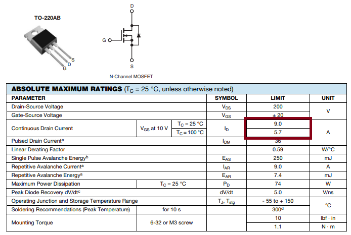
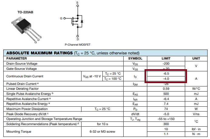
Let's use power MOSFETs for the H-Bridge circuit. We will be using the N-Channel MOSFET IRF630 and the P-Channel MOSFET IRF9630. Because they are power MOSFETs they can handle a lot of current flowing through them and for sure meet the maximum current specs for our motor (500 mA).
MOSFETs are controlled by voltage. So as long as the MOSFETs are TTL compatible (transistor Vgs turns on at 5V or 3.3V) then we are in good shape to connect the microcontroller ouput pins directly to the transistors.
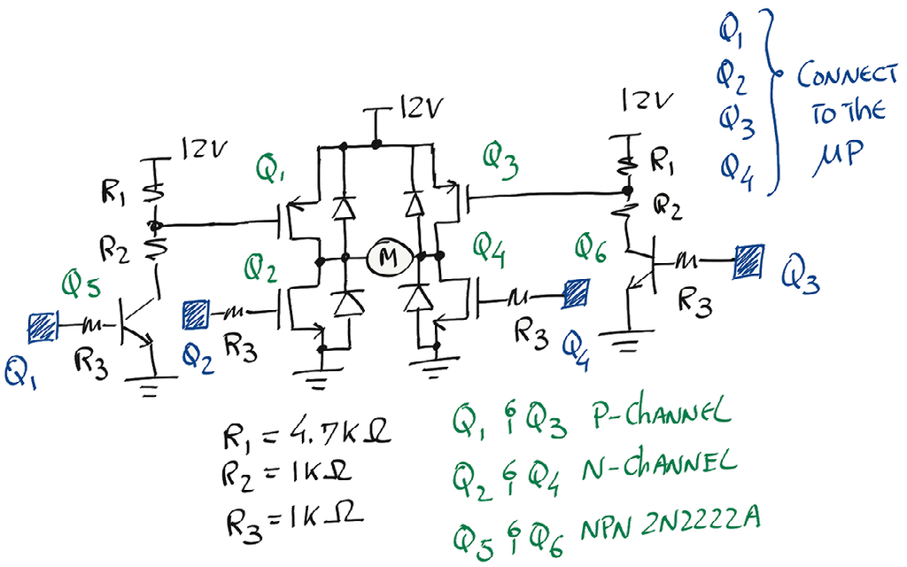
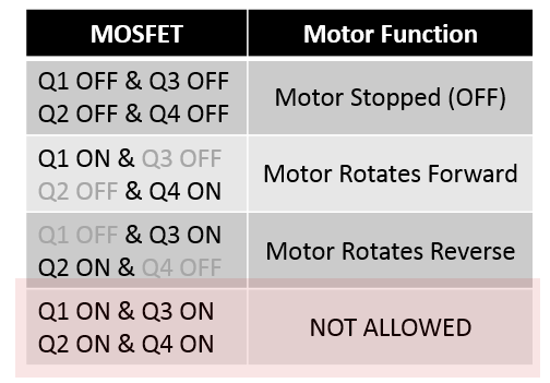
This is one example of connecting P-Channel and N-Channel MOSFETs to build an H-Bridge motor driver. The terminals in blue will connect to a microcontroller. Now we only need to make sure that we follow table below in order to control the motor direction without damaging the transistors.
Do we need heatsinks on the MOSFETs?
To understand if we need heatsinks we need to do the following steps:
- Look for the RDS on the respective datasheet. Keep in mind that RDS will vary with Vgs. So the limit (or Max) stated in the description of the MOSFET, may not apply to your circuit.
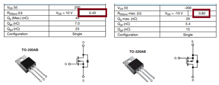
- Once we know the on-resistance, we can use the maximum load's current (500mA) to calculate how many watts the MOSFET will dissipate.
- Now let's calculate the maximum power dissipation that transistor can handle without heatsink. Look for the maximum junction-to-ambient temperature and maximum junction-to-case temperature.
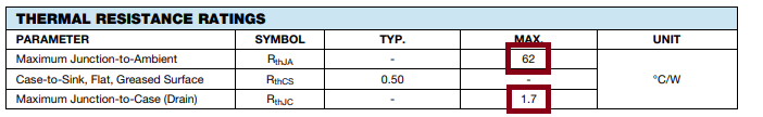
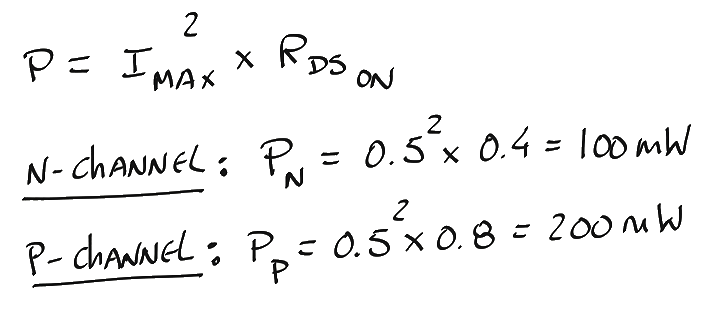
- Apply the following formula:
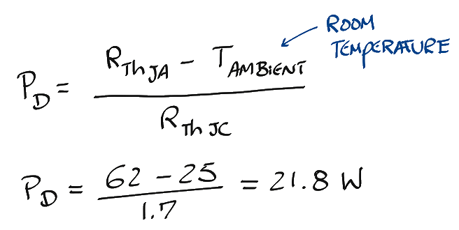
Because Pn and Pp are less than PD there is no need for a heat sink. If Pn and Pp were bigger than PD, you will need a heatsink.
Simulation (switch to pSpice)
Using Multisim Live we can validate the circuit.
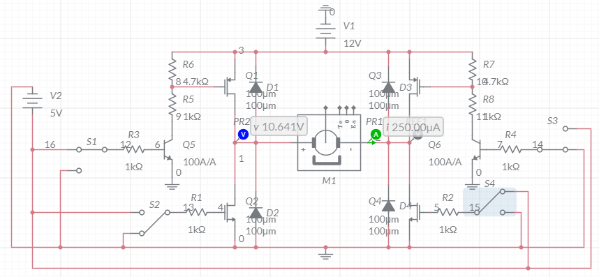
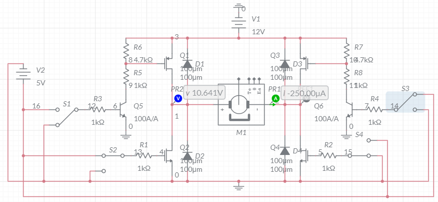
We are able to reverse the current that flows through the motor.
Build
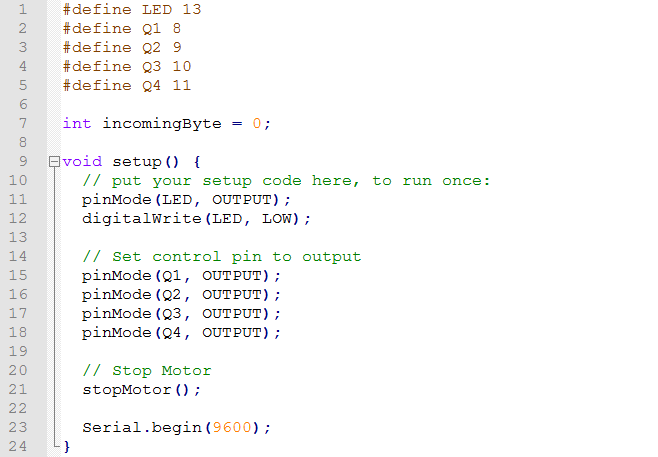
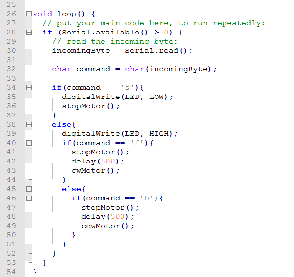
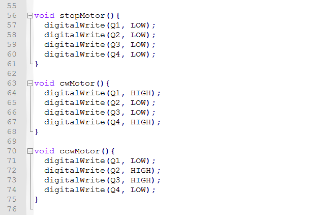
Arduino Code
We will be using the serial monitor of the Arduino IDE and send commands to control the direction of the motor.
- Character 's' -> stop the motor
- Character 'f' -> motor rotates one direction
- Character 'b' -> motor rotates opposite direction
Summary
With this circuit we can turn on an off a motor, we can control the motor speed (include a PWM into the code) and we can control the motor direction.