Basic Circuit DC Motor Driver
Part 1: Basic DC Motor Driver
Let's go over on how to design, build and test a basic DC motor driver that allows a microcontroller (e.g. Arduino) to control the motor.
Requirements
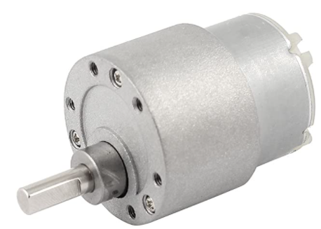
The motor that we will be controlling can handle 12V and a maximum current (Imax) of 500 mA.
If we connect the motor directly to a power supply and apply 12V and if there is no load on the shaft, the motor will run freely with a current less than Imax.
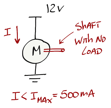
With this configuration we are not able to control the motor with a microcontroller. We need to include some sort of switch that allows to turn on and off the current that flows through the motor.
Transistors are good candidates to be used as switches to control the current that flows through the motor. There are different types of transistors but we will focus on using BJTs for this motor driver.
BJT Basic Driver
Design
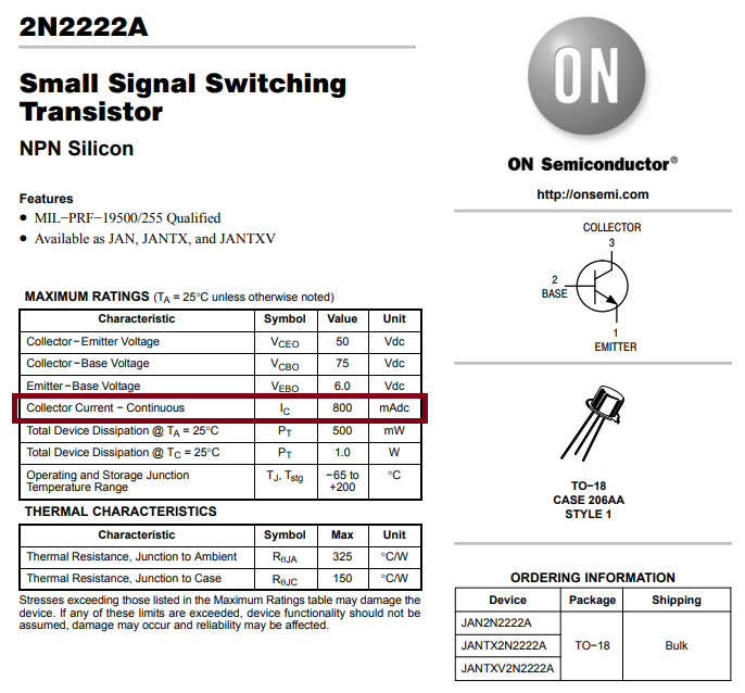
Let's use the BJT 2N2222A as a driver for this first circuit. If you look at the datasheet of the 2N2222A you see that the maximum current that the collector can handle is 800 mA, which is less than the motor maximum current (Imax = 500 mA). This transistor is a good candidate to be used as a driver for this specific motor.
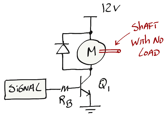
Remember that BJT's are controlled by current. Connecting the motor to the collector terminal (pin 3) of the 2N2222A, we will be able to control the current that flows through the motor by adjusting the current that flows through the base terminal (pin 2) of the transistor. The signal block is representing the microcontroller and don't forget to connect a diode in parallel with the motor to protect the circuit from the motor back EMF.
Analysis
Let's do a quick circuit analysis to understand the currents involved in this circuit. We know that the current at the collector (Ic) is beta times greater than the current at the base (Ib).
Beta is the DC current gain of the transistor. If we check the datasheet we will see that it can have different values based on the current that is flowing through the collector and the voltage between the collector and emitter. For a rapid analysis we will use a beta of 100.
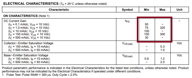
To make this analysis easier, we will be designing the circuit to operate at the edge of saturation so we can use the value of beta instead of beta forced.
With that, we find the following currents flowing through the transistor:
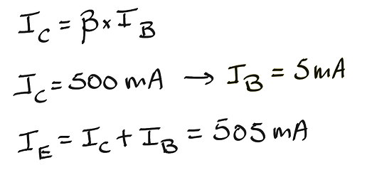
Notice that we use the maximum current that the motor can handle to find the maximum current that we need at the base.
Now the question is, why do we connect RB to the base of the transistor?
In this particular circuit for two reasons:
- Reason 1: in general you can't control the amount of current from a microcontroller output pin. However, you can control the amount of voltage if the output pin has pulse width modulation (PWM) capability or if you have a certain logic level voltage available at the output pin (e.g. 5V or 3.3V). By varying the signal voltage and with RB connected to the base terminal you can control the current at the base (Ib).
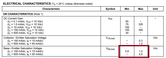
- Reason 2: If you supply a voltage to the base that is greater than Vbe, you will damage the transistor. RB is there to guarantee that Vbe is the same no matter what voltage comes out of the microcontroller output pin. [Note: This statement is true if we disregard changes in temperature].
Let's go over some examples. Let's turn the motor on and off first, and let's assume that the microcontroller ouput pin voltage (signal) is 5V for on and 0V for off.
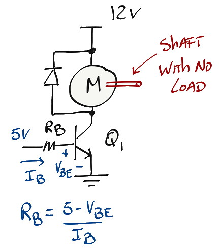
If the input signal is 5V, I can apply ohm's law to find RB. The value of Vbe can be found on the datasheet of the 2N2222A.
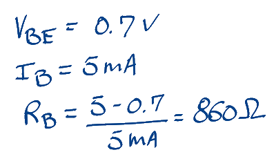
For this case with a 5V input signal and RB = 860 ohms, the transistor will have a base current of 5 mA and a maximum current at the collector of 500 mA.
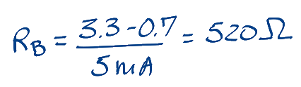
If the microcontroller has a different logic level output for on state, let's say 3.3V, then RB will have a different value.
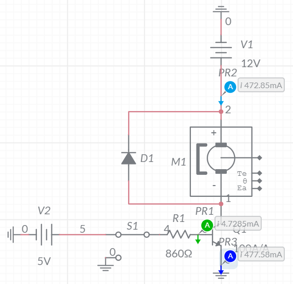
Simulation (switch to pSpice)
Using Multisim Live we can validate the currents that flow through the transistor. Multisim has a model for a DC motor with permanent magnets making our life easier to simulate this circuit.
Build
The design and analysis done so far will turn the motor on and off.
If we want to control speed we need to apply a pulse width modulation (PWM) at the base of the transistor.
Summary
With this basic circuit we can turn on an off a motor and we can control the motor speed by applying a PWM signal at the base of the transistor. However, If you want to control the direction of the motor this circuit is not sufficient. For that we need to build a different motor driver (H-Bridge).