2 Wheel Balance Robot
2 Wheel Balance Robot
✔️ Introduction
This project describes a 2 wheel balance robot system. There are several designs available online, but we will be creating the design from scratch. We will be designing the chassis using OnShape, a PCB board with the motors driver, IMU, encoders, and a capability to control the robot over WiFi. Later to “spice” things a bit, we will add an additional challenge to the balancing system.
✔️ Design Stage
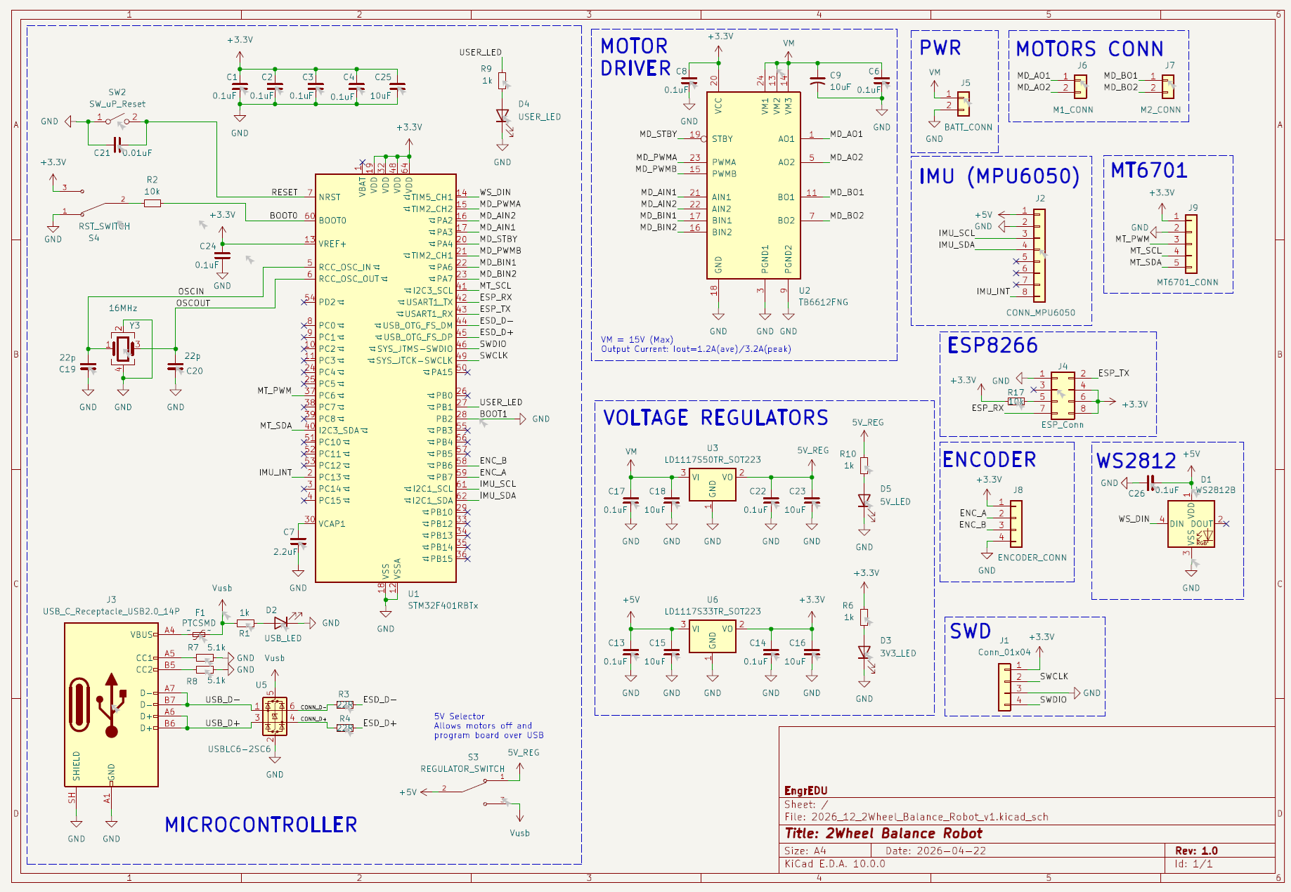
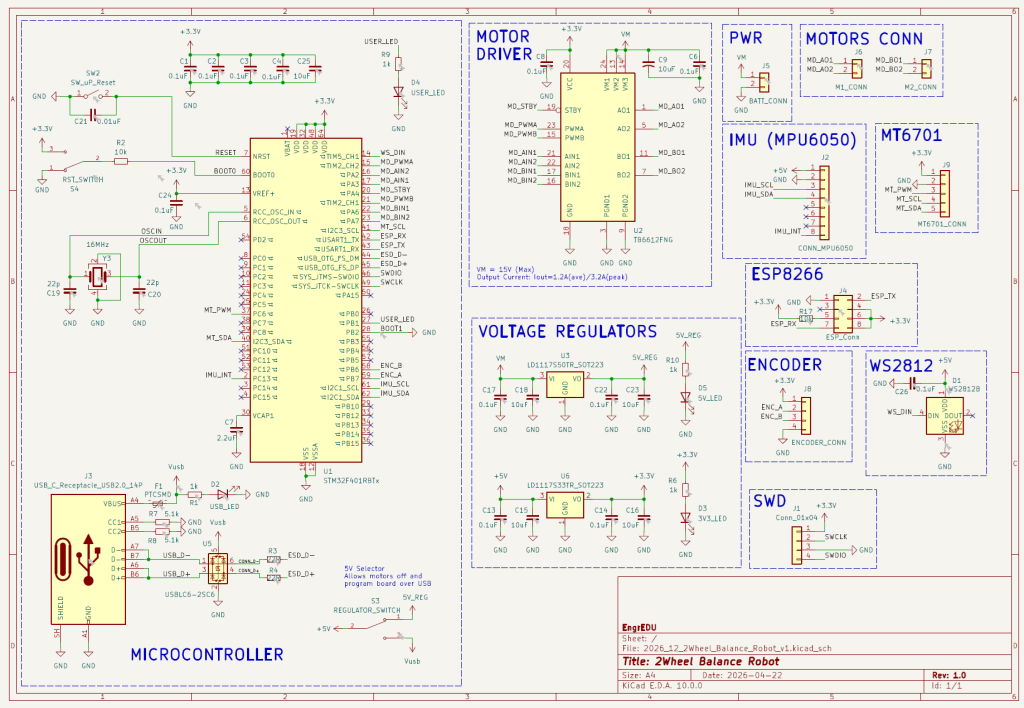
As always we start with the block diagram of the system that we are designing. The minimum systems has two motors, a driver to control the motors (TB6612), one IMU (MPU6050), one magnetic encoder (MT6701), one RGB LED (WS2811), and one communication module (ESP8266).
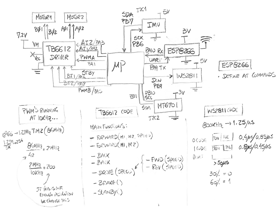
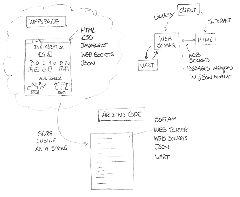
The ESP8266 is used to adjust the PID controller gains and steer the robot in real time. The user connects to the ESP8266 own network over WiFi and the device used gets assigned an IP address. The user opens a browser and it has access to the GUI to interact with the robot. The ESP8266 uses UART to communicate with the main microcontroller.
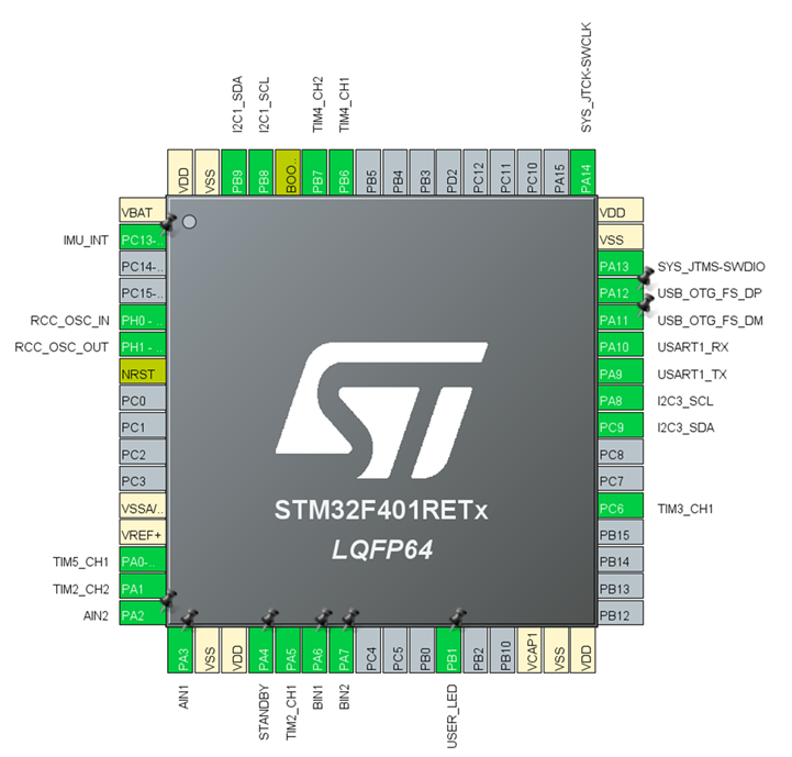
The microcontroller used in this project is an STM32F401RBT6 with 64 pins and an LQFP package.
The pins were selected so we could interface all the required peripherals using timers, PWMs, encoders, I2C and UART features.
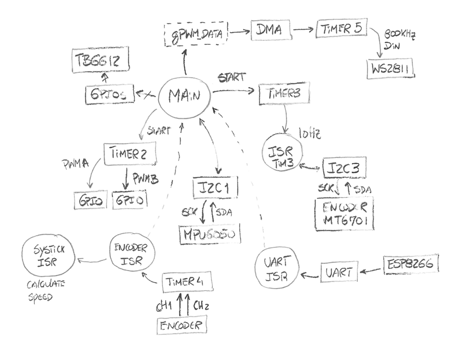
The code diagram is presented below. It is an attempt to show how the code will be structured later to control the robot using the peripherals selected with the STM32CubeMX.
✔️ Prototype Stage
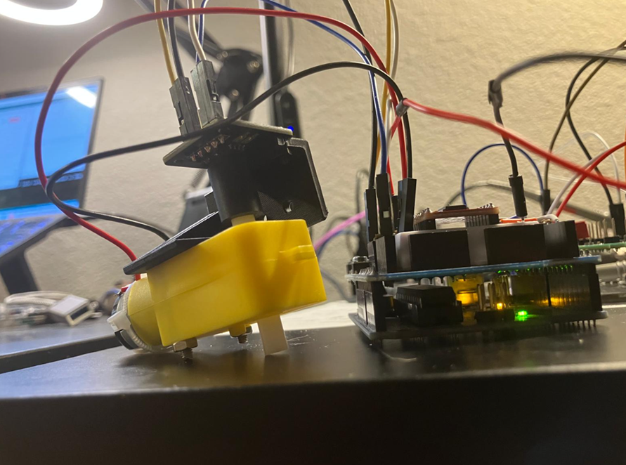
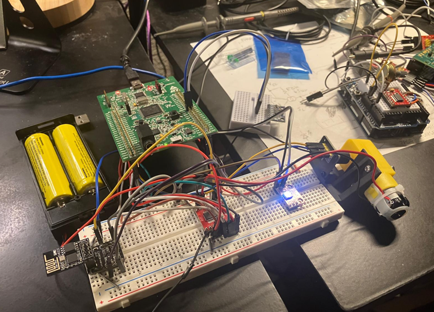
Since I needed to design and find a way to attach the magnet and the encoder to the motor, that setup was tested separately first.
Next, since I don’t have an STM32F401 development board, I used the STM32F407 discovery board to test all peripherals and components and made sure that the code diagram presented in the previous section was working as intended.
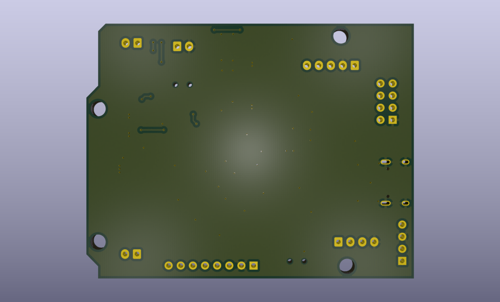
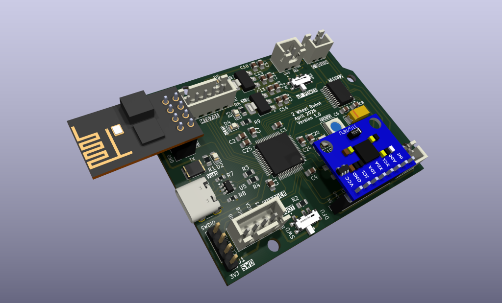
✔️ Assemble Stage
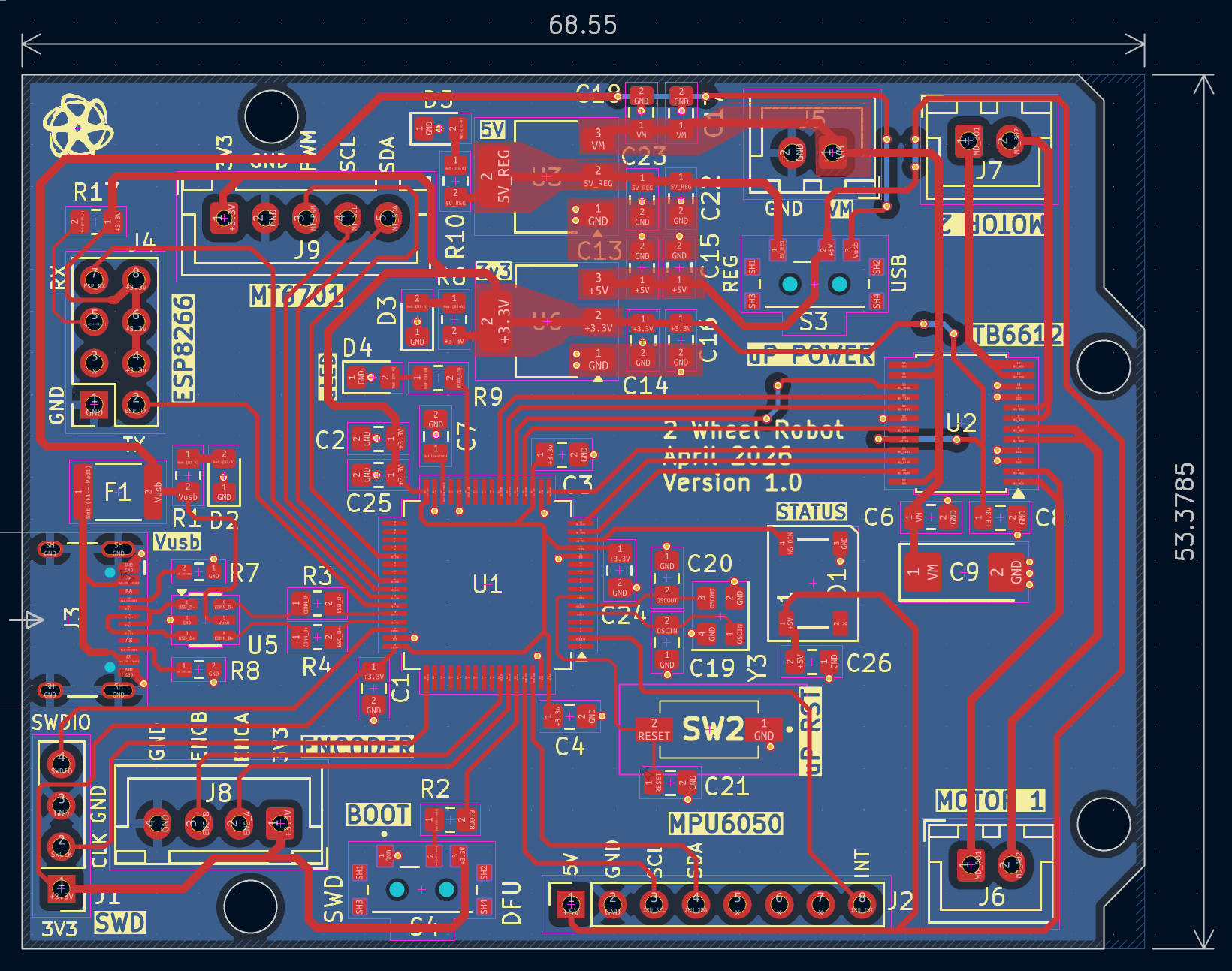
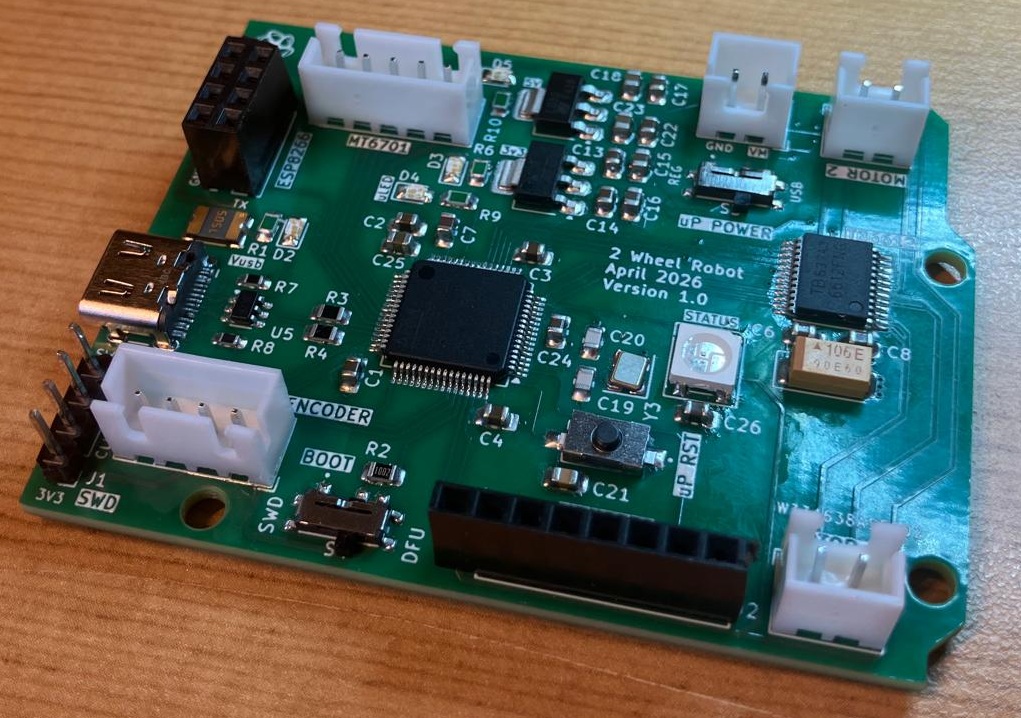
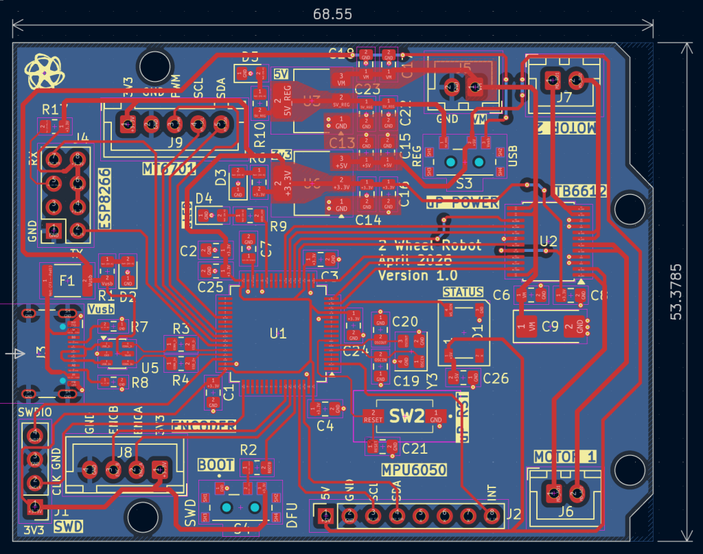
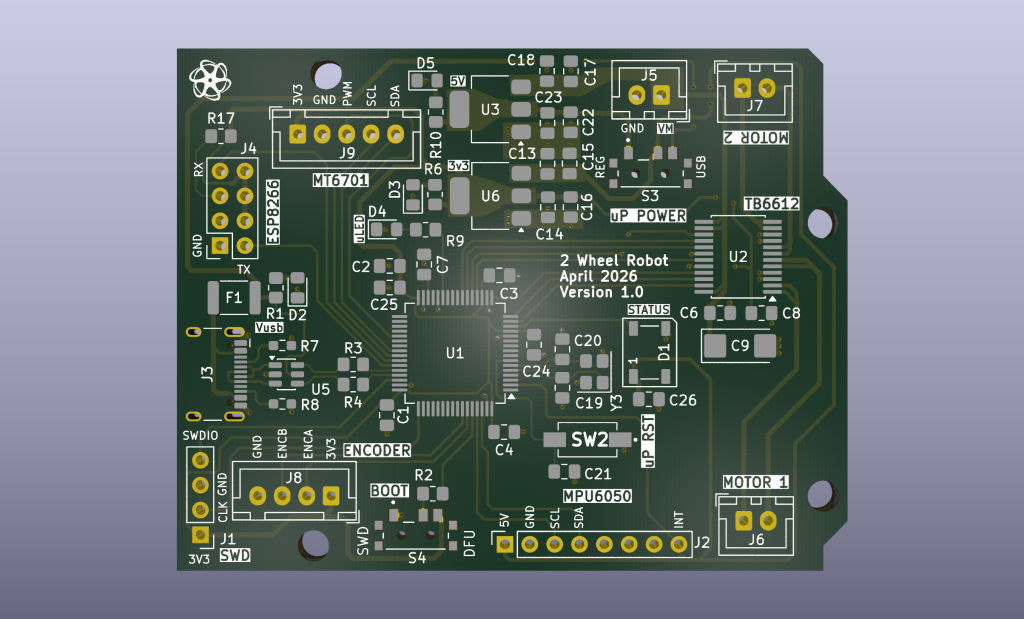
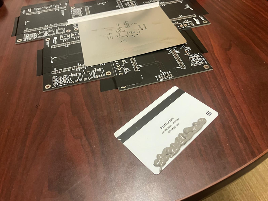
The boards were manufactured by PCBWay.
This time I ordered a stencil and as always a stellar service.
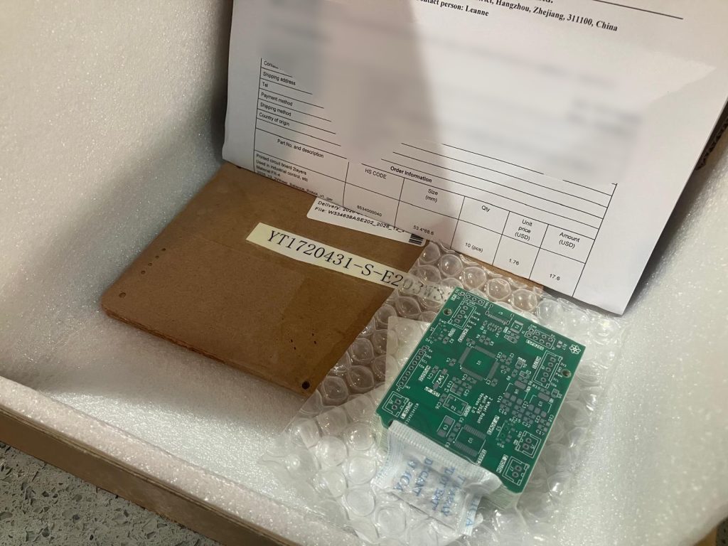
The quality of the stencil is very good and I really like how they made it small and easy to use.
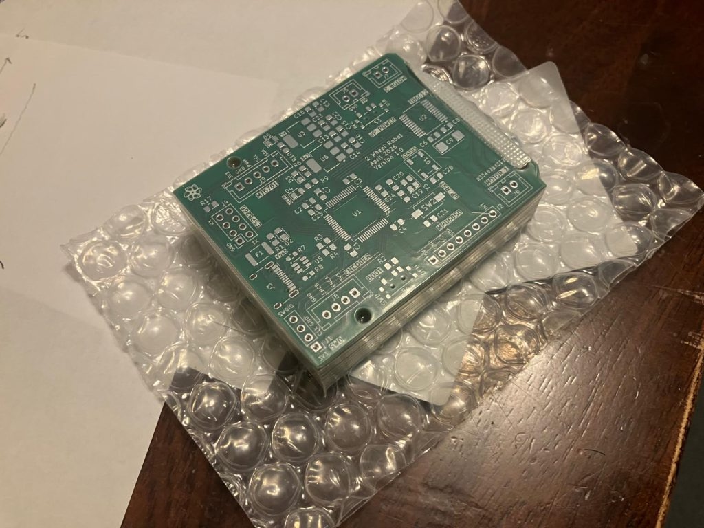
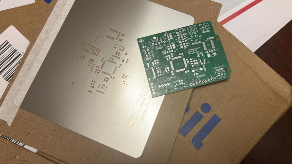
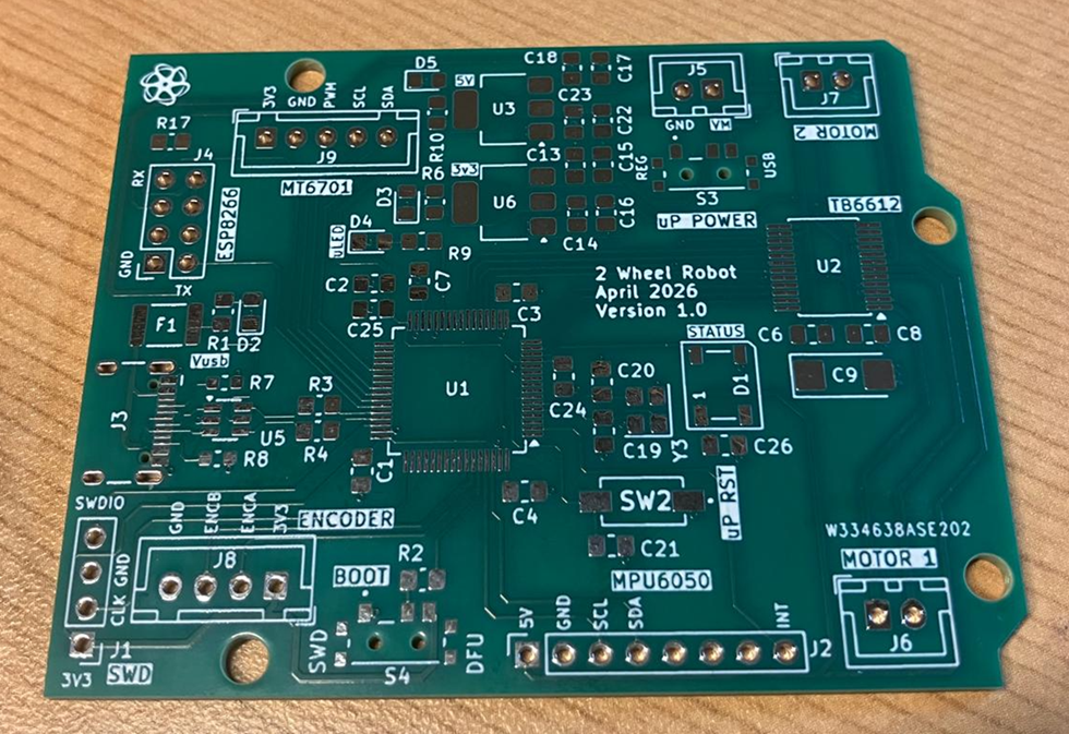
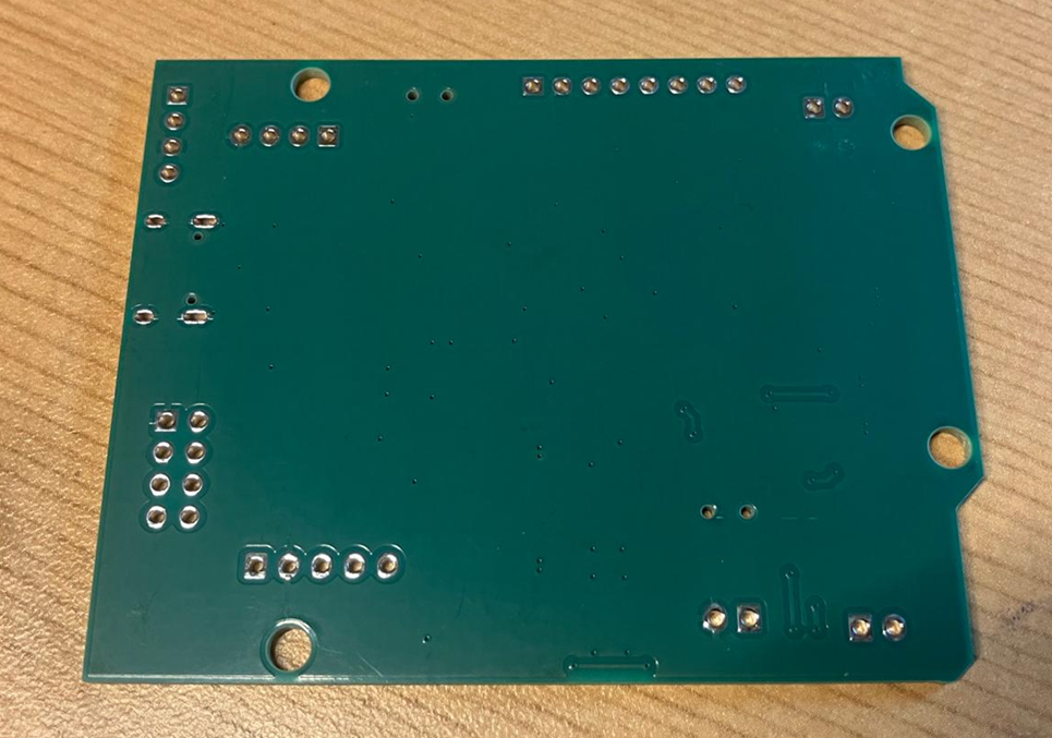
Assembled in house.
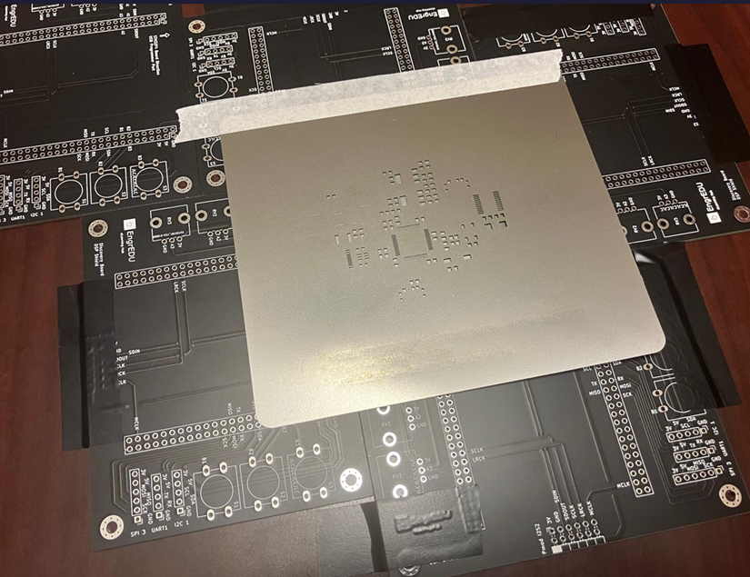
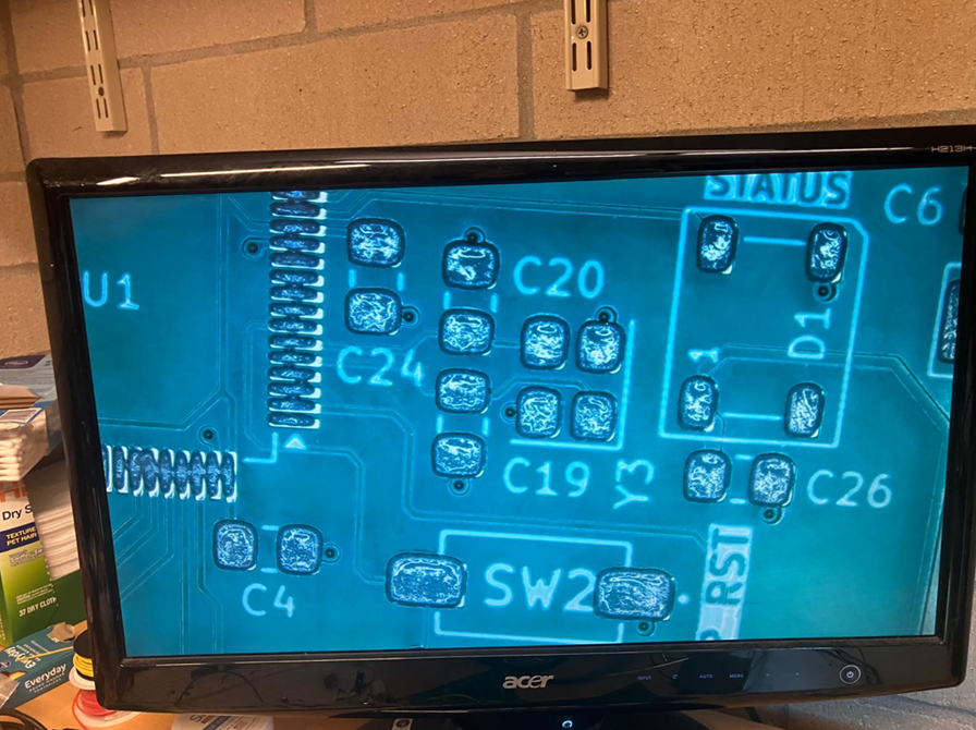
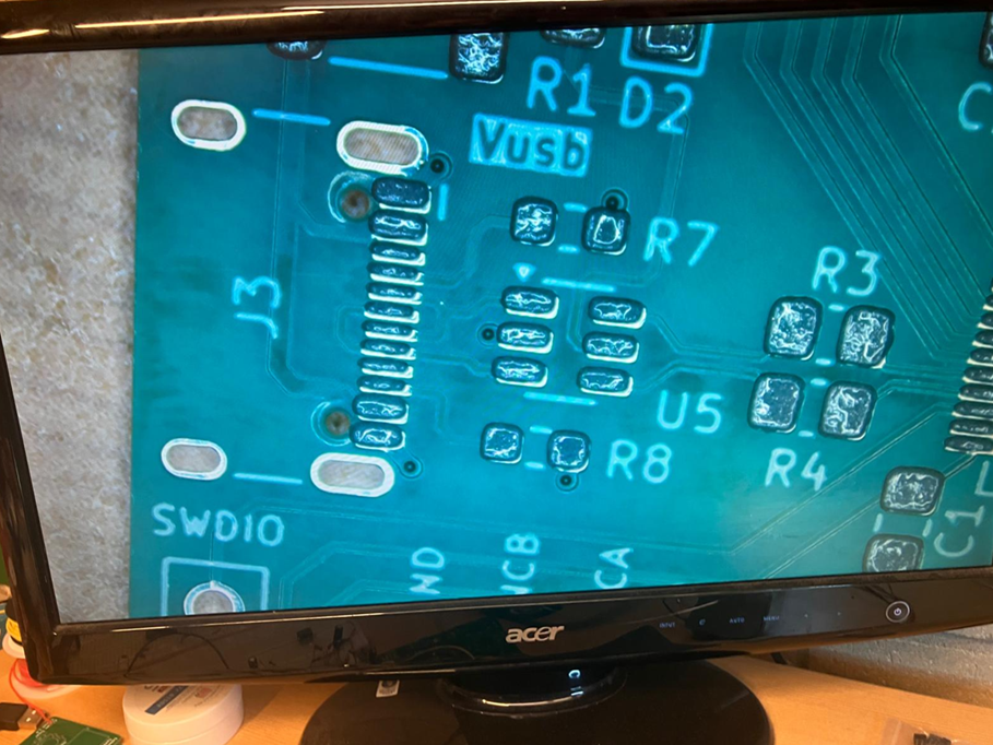
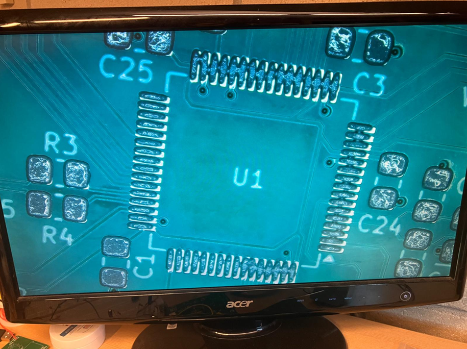
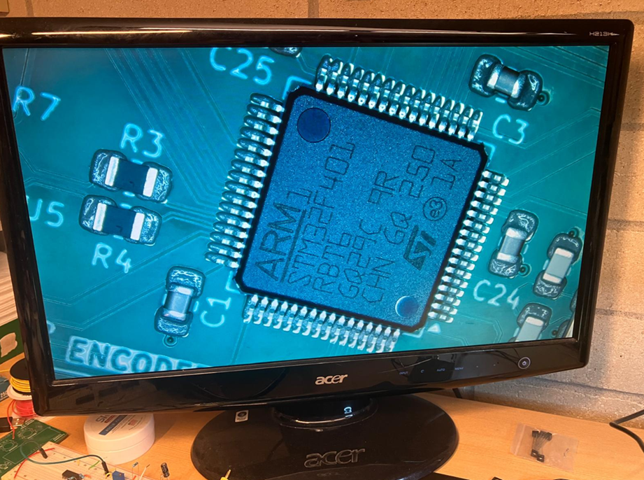
Components place by hand:
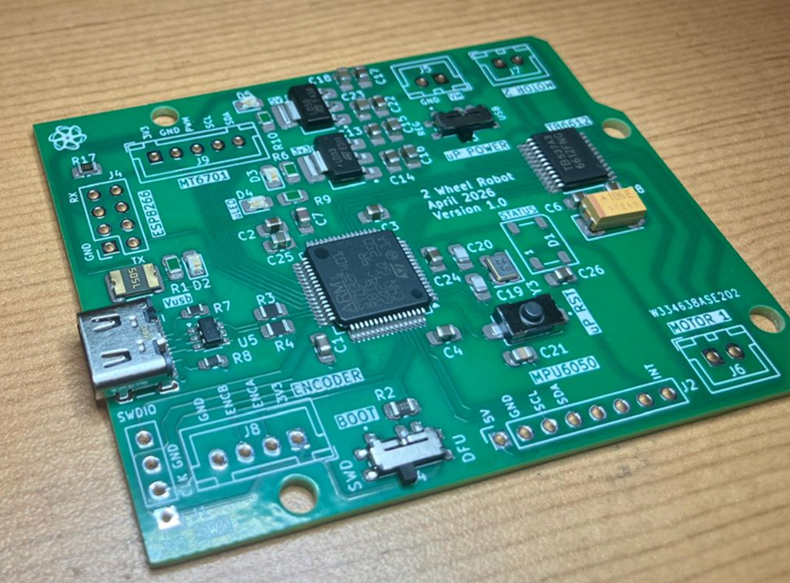
After reflowing the solder paste:
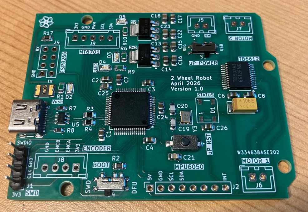
I needed to fix a couple of solder bridges, and then I flashed a blink LED program to make sure that everything got soldered properly.
🔧 3 Wheel Robot
The goal with this stage is to make sure that all components and PCB works before we start developing the balancing code with the respective control algorithm.
We will focus on testing the HAL drivers to control the motors, communicate with the ESP8266 over UART, IMU and encoders readings over the I2Cs, and interact with the RGB LED.
Chassis
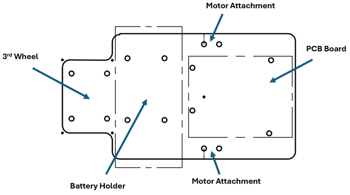
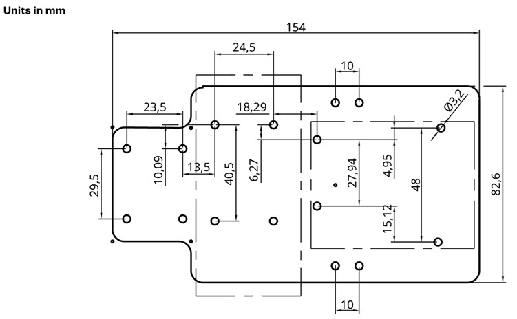
You can download the DXF file for the chassis under the GitHub Repository and laser cut it with your preferred material. I will be using a 3mm thick acrylic. For simplicity, all holes are M3 size.
Communications
To control the robot, I will be using the ESP8266 as a remote web server that I can connect to and send commands to steer the robot. We will be rendering basic telemetry, such as encoder and IMU readings.
The communication protocol between the ESP8266 and the STM32F401 over UART is simple:
- w – move forward
- s – move backwards
- a – move left
- d – move right
- x – stop
Telemetry packages have the following format:
- $speed,roll,pitch,counter\n
Robot Interaction
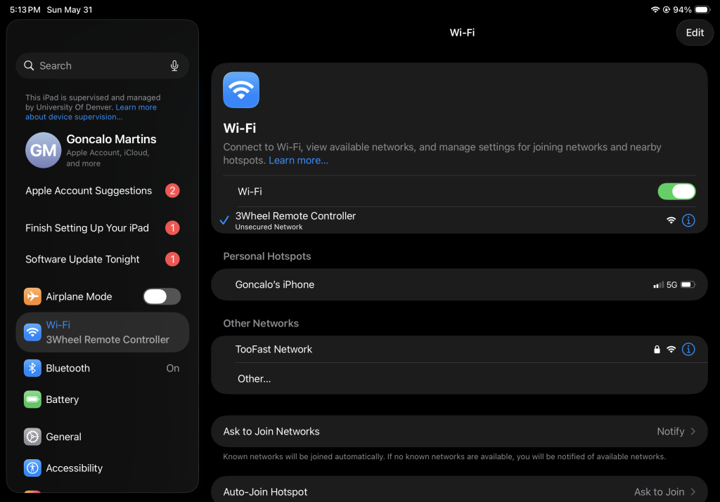
To connect to the robot, open the WiFi settings in a computer/iPad/smartphone and find the “3Wheel Remote Controller” access point. Connect to it.
Open a browser and type the following IP address: 192.168.4.1
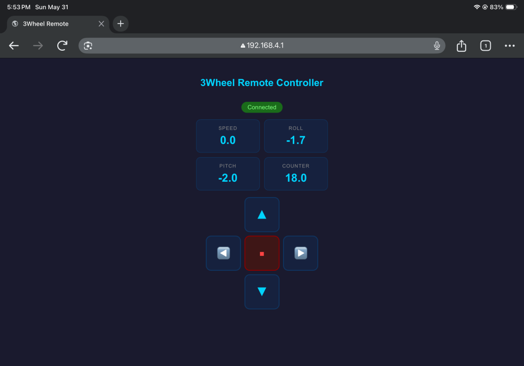
You should be able to control the robot by pressing the arrow keys and receive telemetry accordingly.
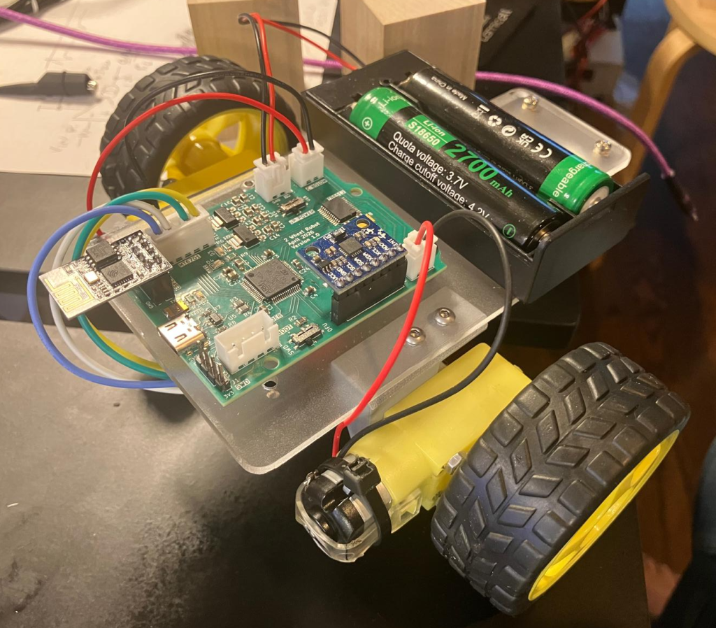
At this point, all the code works as expected and we can move on to the balance code of this project.
🔧 2 Wheel Balance Robot
soon…
✔️ Students Results
✔️ GitHub Repository
- KiCad 10.0 Files
- CAD Files
- 3 Wheel code + ESP8266 code
- 2 Wheel code + ESP8266 code
✔️ References
N/A
Sponsor