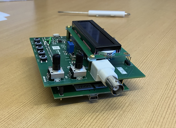
DDS Function Generator STM32F407 Shield
DDS Function Generator STM32F407 Discovery Board Shield
Introduction
This project implements a DDS Function Generator shield for the STM32F407 Discovery Board done for the Embedded Systems class of 2024.
Note: DDS stands for Direct Digital Synthesizer and you can check this link for more details.
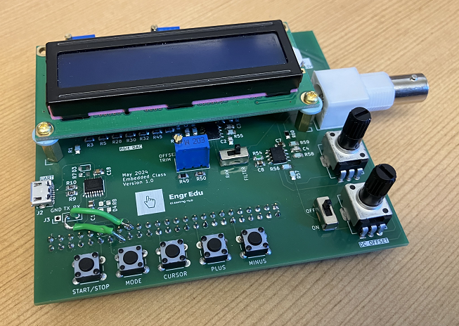
The DDS Discovery Board Shield has the following features:
- 8bit R-2R ladder DAC
- UART communication for external control
- 5 user buttons
- A 16x2 LCD screen
- A gain stage and DC offset output waveform control
- External +/- 13V for the Op Amps.
Reference Project
The original motivation for this project is based on the DDS Function Generator from Amazon (Link).
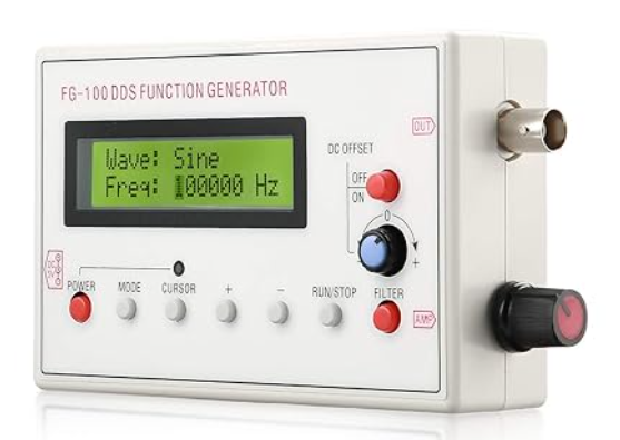
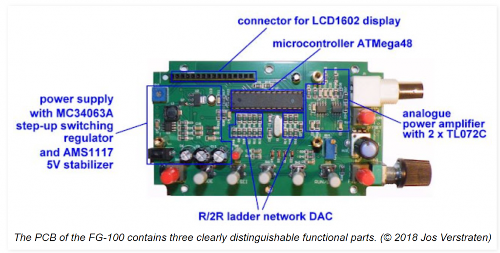
There is a blogpost (Link) that goes over some details of this DDS device, in particular the different functional parts of the system.
There are also plenty of YouTube videos showing the pros and cons of this DDS Function Generator. However, you can't find many resources showing how to build one from scratch.
I will be replicating the majority of these functional parts and providing additional information about the circuits and code.
To reduce the complexity of the PCB board, this shield will not include an onboard microcontroller, neither a onboard +/- 13V voltage regulator. However, the user will have the ability to control the DDS by UART, offering an additional feature to the existing system.
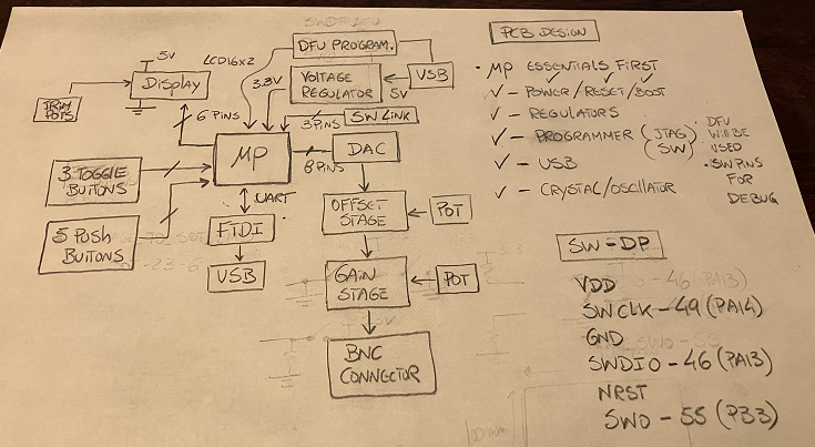
Design Stage (Block Diagrams)
Overall System Block Diagram
Let's start with showing the block diagram with all the functional parts of the new DDS Function Generator.
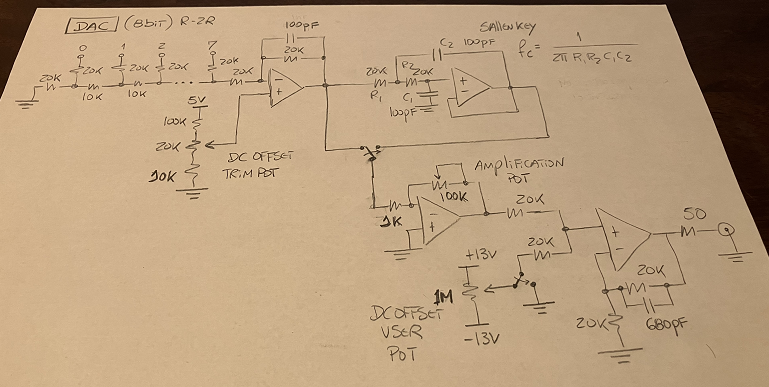
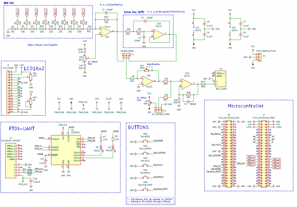
DAC Schematic (Draft)
Instead of using an off-the-shelf DAC, I will be building one from scratch, similar to the FG-100 DDS board. I will include an offset correction circuit, gain stage and additional filtering.
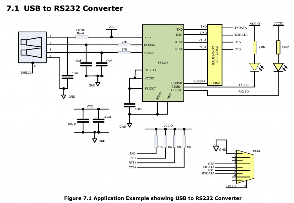
USB to UART (FTDI)
For the USB to RS232 circuit, I will be using the FT230XS-U from FTDI and using their datasheet application example as a reference design.
For the rest of the components, buttons and LCD, the PCB design schematic should be sufficient to understand how the integration of those elements were done with the board.
Prototype Stage
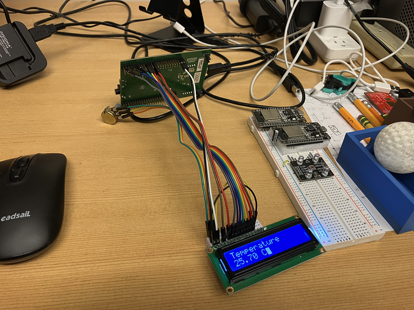
LCD Test
The LCD was the first element to be tested. I will be using the common 16x2 serial LCD screen used in several online Arduino projects.
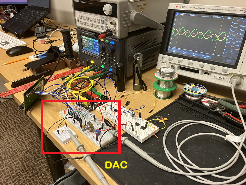
R-2R DAC Test
For the DAC, I designed an 8 bit R-2R ladder circuit.
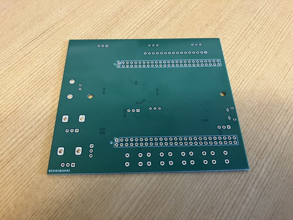
PCB Design
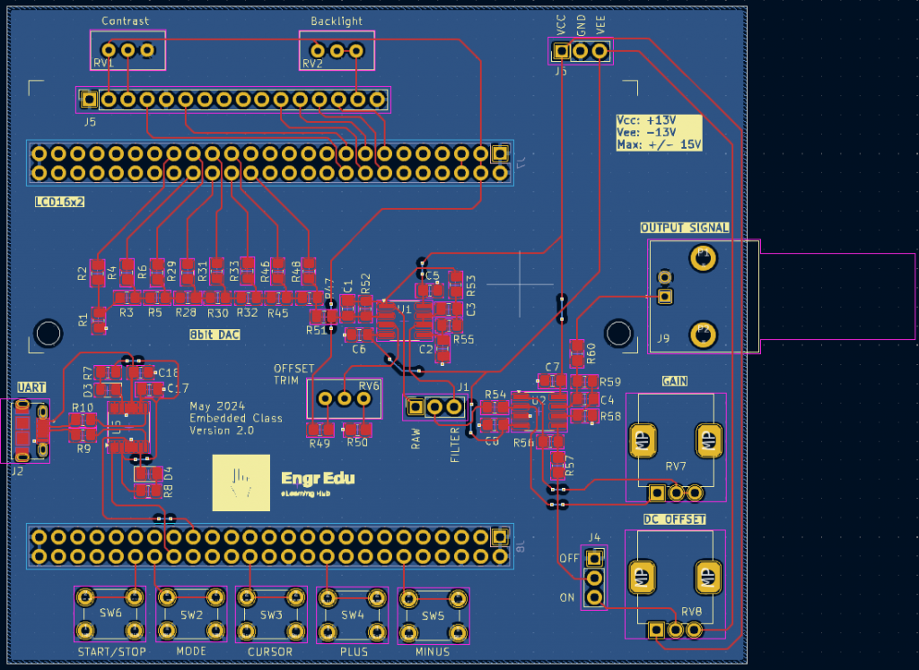
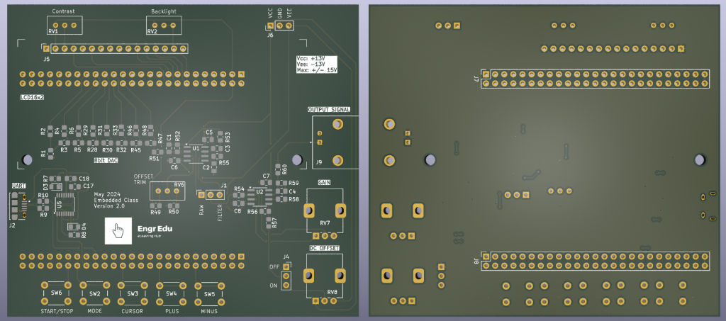
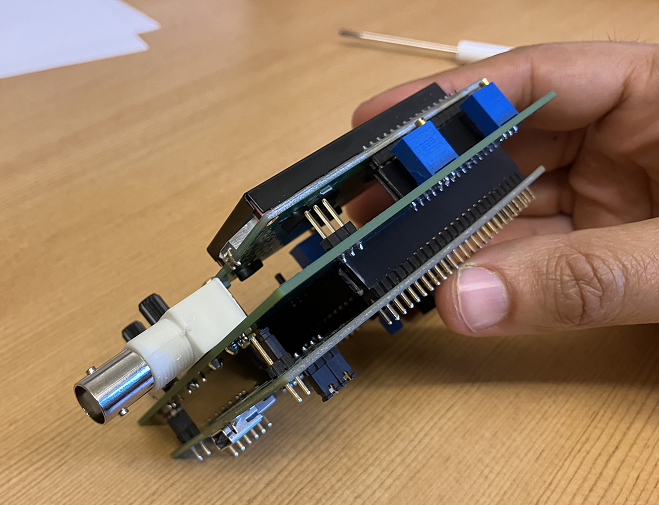
Assemble Stage
The boards were manufactured by PCBWay.
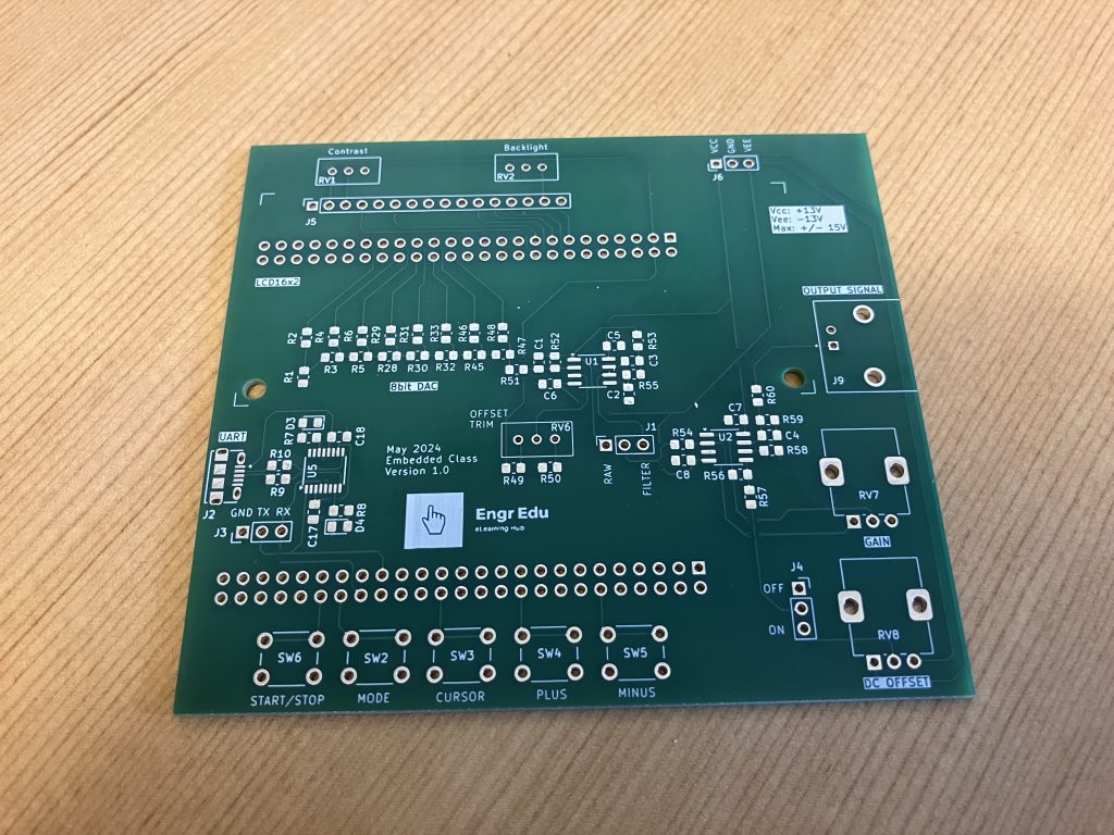
Assembled in house.
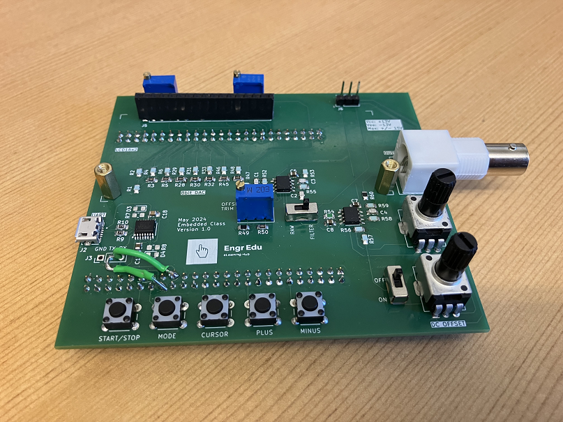
Note: I made a mistake on the original board on the RX and TX connections that needed to be swapped. All files on the GitHub repository, schematics and layouts shown on this article have that mistake corrected.
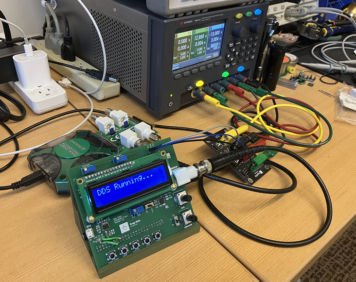
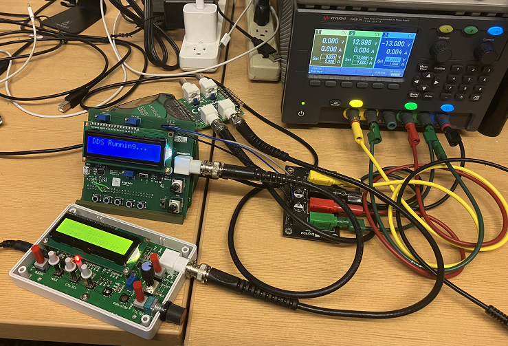
Testing Stage
For the testing phase, we will be using the following equipment:
- Oscilloscope from Digilent, Analog Discovery 2
- External power supply: +/-13V
- DDS Function Generator
- UART interface: Realterm
LCD Test
Cycling through different types of output waveforms.
UART Test
The same information that shows on the LCD is sent over UART.
We can send commands over UART to control the DDS Function Generator.
UART Commands List
- #DDS:ON*
- #DDS:OFF*
- #MODE:SINE*
- #MODE:COSINE*
- #MODE:TRIANGLE*
- #MODE:SQUARE*
- #MODE:SAWTOOTH*
- #MODE:SAWTOOTH_REV*
- #FREQ:<number>*
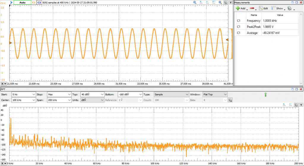
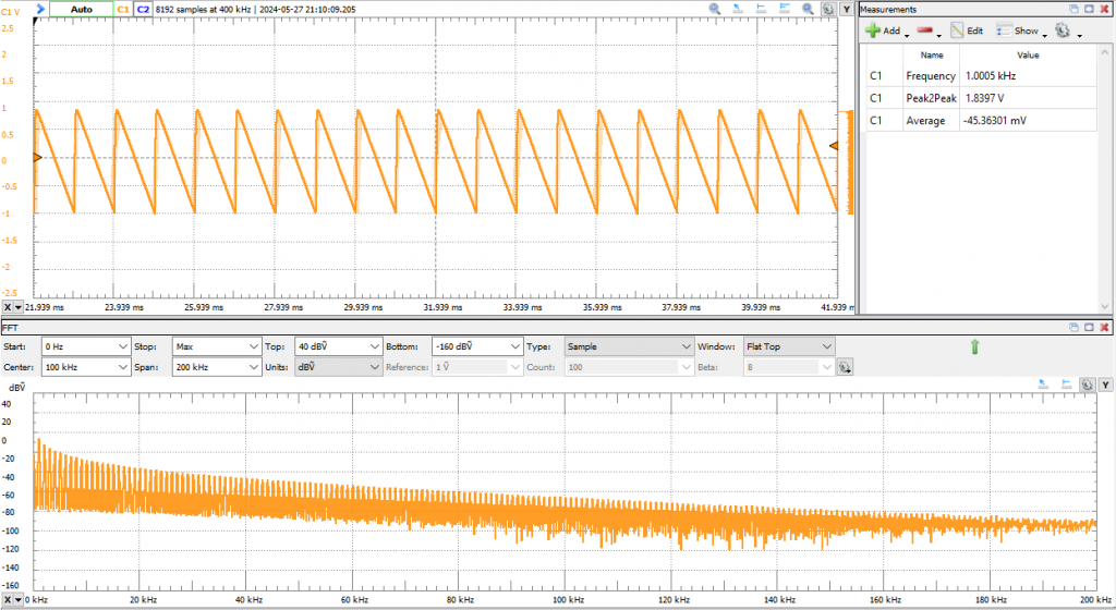
DAC Test
Sine waveform test and respective FFT.
Sawtooth waveform test and respective FFT.
Note: While the DDS is running, the only button that works is the start stop button. However, it is possible to change the waveform type and frequency at anytime using UART commands.
System Software Architecture
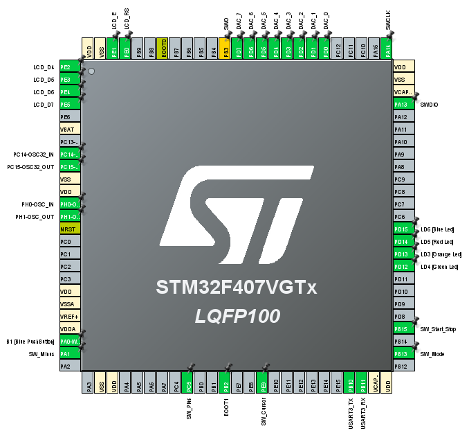
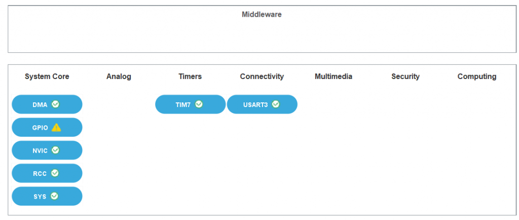
STM32F407 Hardware Peripherals
To understand better how the software is running, it is important to highlight from the STM32F407 block diagram, which hardware peripherals are being utilized.
Pinout View
System View
Software Architecture
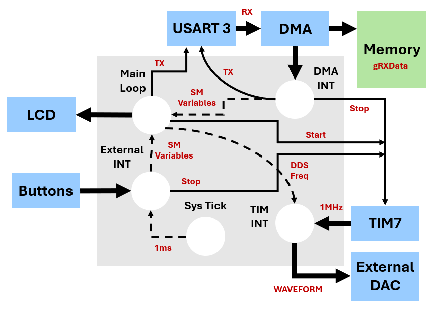
Code will be explained in this section soon...
Performance Test
This section shows a comparison between the STM32F407 Discovery Board Shield and the FG-100.
Oscilloscope Measurements Information
I will be using the same oscilloscope as in the previous section from Digilent, Analog Discovery 2 (Link). For all oscilloscope measurements, the FG-100 will be the blue line (channel 2) and the Shield with be orange line (channel 1).
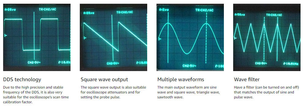
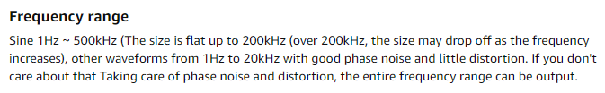
FG-100 Features (Link)
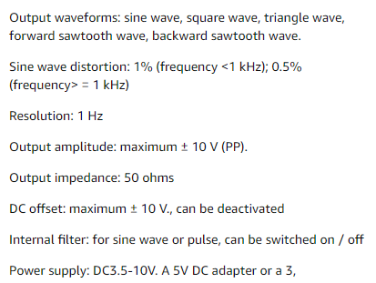
Output Amplitude Maximum
Both devices were set to output a sine waveform at 10kHz and the amplitude was adjusted to 20Vpp.
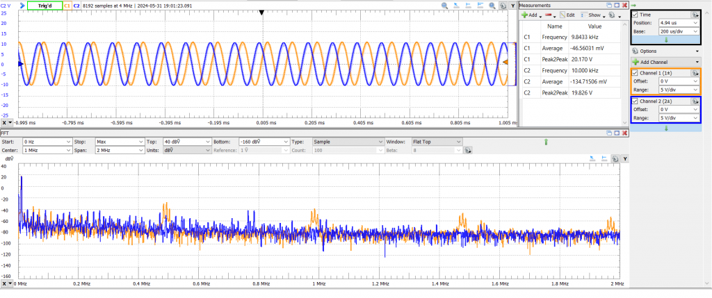
- The shield is running the Op Amps from an external power supply which makes it easier to achieve this spec.
- The FG-100 amp knob reaches the limit at around 19.8V
On Board Filter
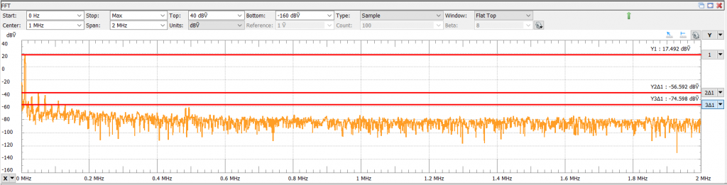
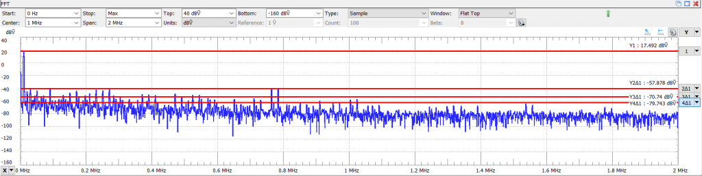
It is interesting to observe the spectrum and how the shield at first glance has more noise than the FG-100. If we analyze the frequencies of those spikes we get the following values: 500kHz, 1MHz, 1.5MHz...
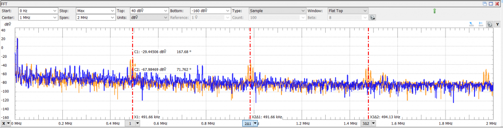
What is going on here? 🤔 These spikes are too consistent to be considered noise. There are in fact a product of a DDS limitation.
"The actual output of the DAC is not a continuous sine wave but a train of pulses with a sinusoidal time envelope. The corresponding frequency spectrum is a set of images and aliases."
Analog Devices - DDS Waveforms Article
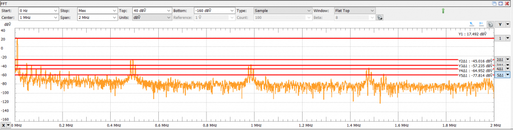
What we see in the FFT are aliased images of the 1MHz sampling frequency used with Timer 7 to sample the DAC.
The on board sallen key low pass filter on the shield was designed to have a cut off frequency around fc=80kHz. If I turn the filter on, all those spikes get filtered. The animation below shows the filter being turned on and off.
You can also see the effect of the filter in the time domain view.
The FG-100 has on board filter too. We can see a reduction of some of the spectrum frequencies but it doesn't have the same impact on the spectrum as the filter on the shield.
DC Offset
The function generator output was turned off and the DC offset button was turned on. Both devices have similar maximum and minimum DC offset values.
Sine Wave Distortion
THD stands for Total Harmonic Distortion and if you are not familiar with how to calculate THD or what THD is, there is a wonderful YouTube video that I recommend watching it before looking at the results below (Link).
The THD for the shield at a frequencies greater than 1kHz and lower than 10kHz with the sallen key filter on, is around 0.2%.
However, with the filter off, the THD is bigger than 0.5%.
The THD for the FG-100 is below the advertised 0.5% for frequencies above 1kHz.
Setting a sine waveform output at 500 Hz, the THD for the shield at frequencies lower than 1kHz with the sallen key filter on, is around 0.3%.
The THD for the FG-100 is below the advertised 1%.
Sine Waveform Output @ 1Hz
Minimum frequency of 1Hz and filter off.
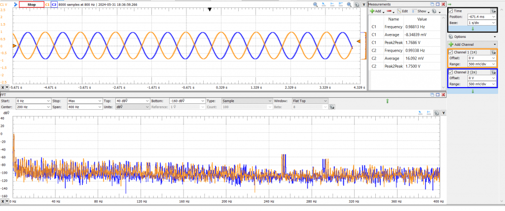
- Both devices behave similar in the time domain.
- The spectrum at lower frequencies is pretty much the same too.
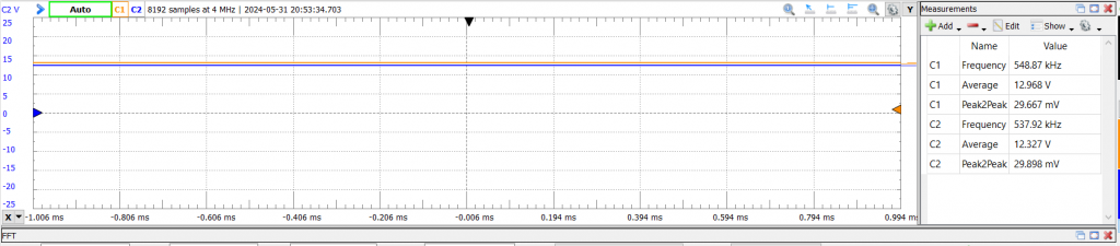
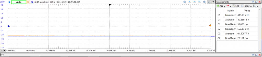
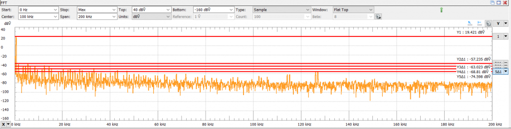
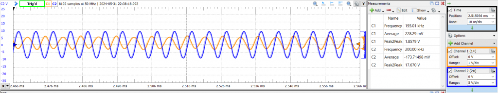
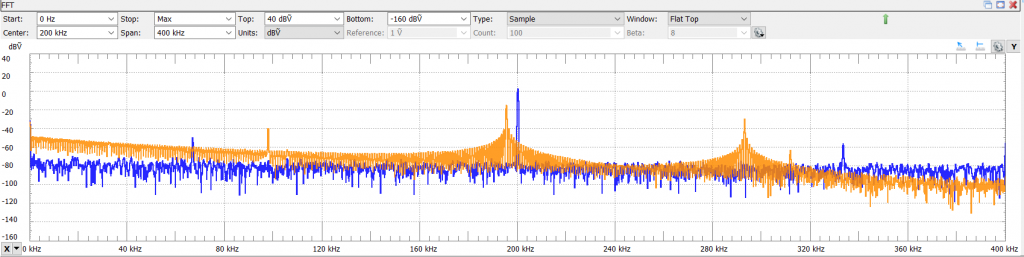
Sine Waveform Output @ 200kHz
The shield didn't perform as well as the FG-100. The maximum amplitude of the output waveform was impacted by a lot and the spectrum has some aliases images (the filter is on). However, the FG-100 has a very clean output waveform and it can maintain a maximum amplitude around 17Vpp.
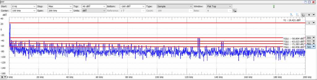
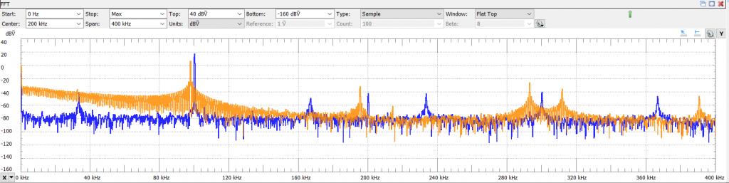
Sine Waveform Output @ 100kHz
The FG-100 still out performs the shield. The maximum amplitude is around 19.3Vpp where the shield is around 6Vpp.
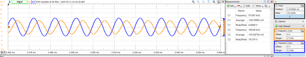
The spectrum for the shield is not the best.
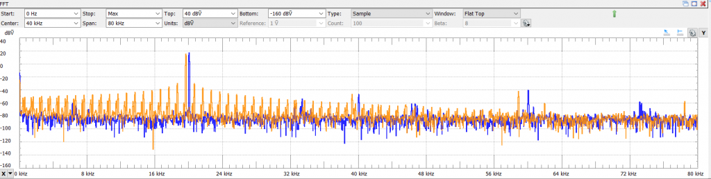
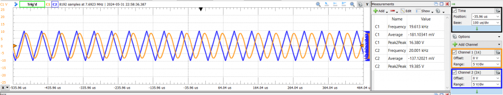
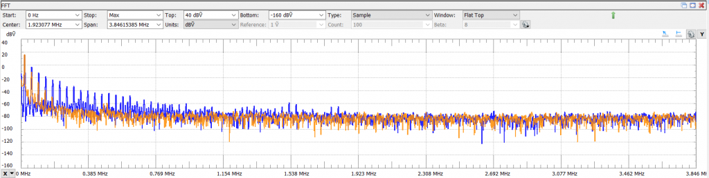
Sine Waveform Output @ 20kHz
At around 20kHz, the shield start to have similar specs to the FG-100 in the time domain.
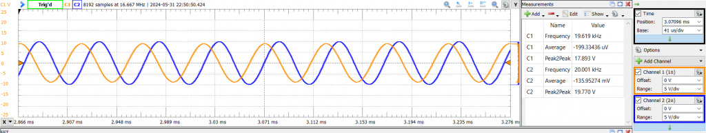
The spectrum for the shield is not the best.
Triangle Waveform Output @ 20kHz
The shield can't reproduce a triangle wave at 20kHz. I suspect that issue is at the capacitor (C1) on the feedback loop from the first Op Amp (U1A). I need to investigate this further.
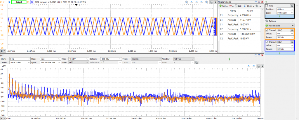
Triangle Waveform Output @ 5kHz
The shield has decent waveforms at this frequency. However, the FG-100 has a good output waveform.
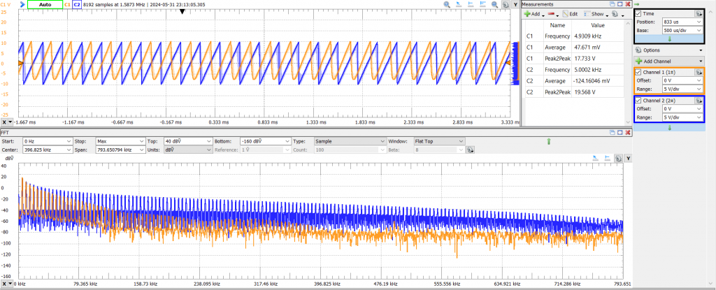
Sawtooth Waveform Output @ 5kHz
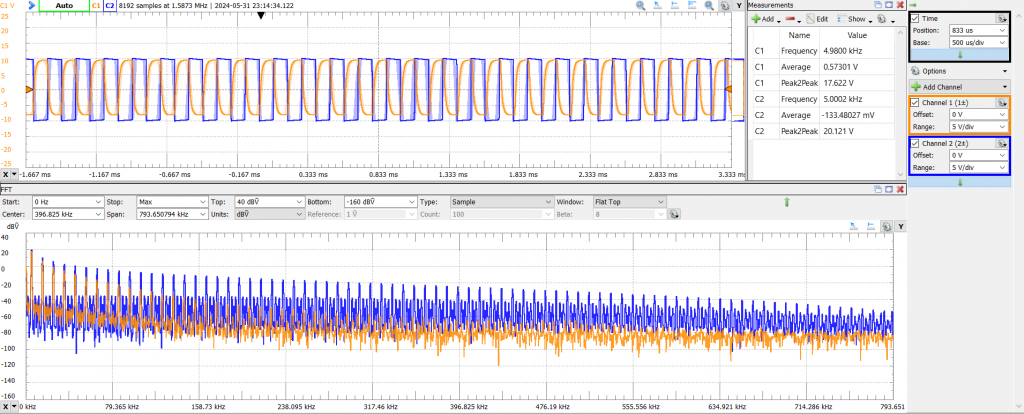
Square Waveform Output @ 5kHz
Summary
The STM32F407 Discovery Board DDS Shield definitely has room for improvement.
For waveforms with a frequency greater than 5kHz, the shield can't reproduce the waveform with the same quality as the FG-100. However, for relatively low frequencies, the shield has similar performance to the FG-100, from 1Hz to an acceptable THD, and a maximum output voltage of 20Vpp.
For future exploration:
- On hardware side, I need to invest time understanding how to improve the analog side of this project, in particularly, find a suitable value for the capacitor (C1) so I can at least increase the output frequency of the waveforms from 5kHz to 20kHz.
- On the software side, I need to invest time understanding a way to measure the real time portion of the code and potentially improve the way that the DDS code is done.
Independently of the issues that I need to fix, I have a platform that can be used to test DDS algorithms and/or generate waveforms that can be useful to test other projects with.
GitHub Repository
References
- [Ref 1] “FG-100 Function Generator Tested”, Website [Article]
- [Ref 2] “Measuring Total Harmonic Distortion THD using an FFT on an oscilloscope”, w2aew YouTube Channel [Video]
Sponsor