uP 1 Uno Shield
uP 1 Uno Shield
Introduction
The main goal with this project is to introduce students that are learning microprocessors for the first time to the design of an Arduino Uno shield, where they can later implement embedded systems concepts such as interrupt routines, timers, mixed signals and digital communications.
Design Stage
We will include as many peripherals as possible in order to support the concepts covered in a typically introductory microprocessors class:
- GPIO
- Interrupts
- Timers (counter, PWM, and watchdog)
- Mixed Signals (ADC and DAC)
- Digital Protocols (I2C, SPI, and UART)
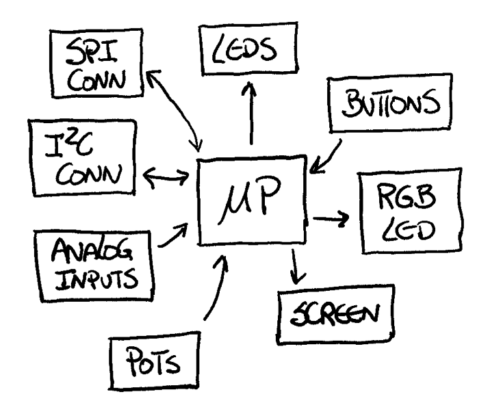
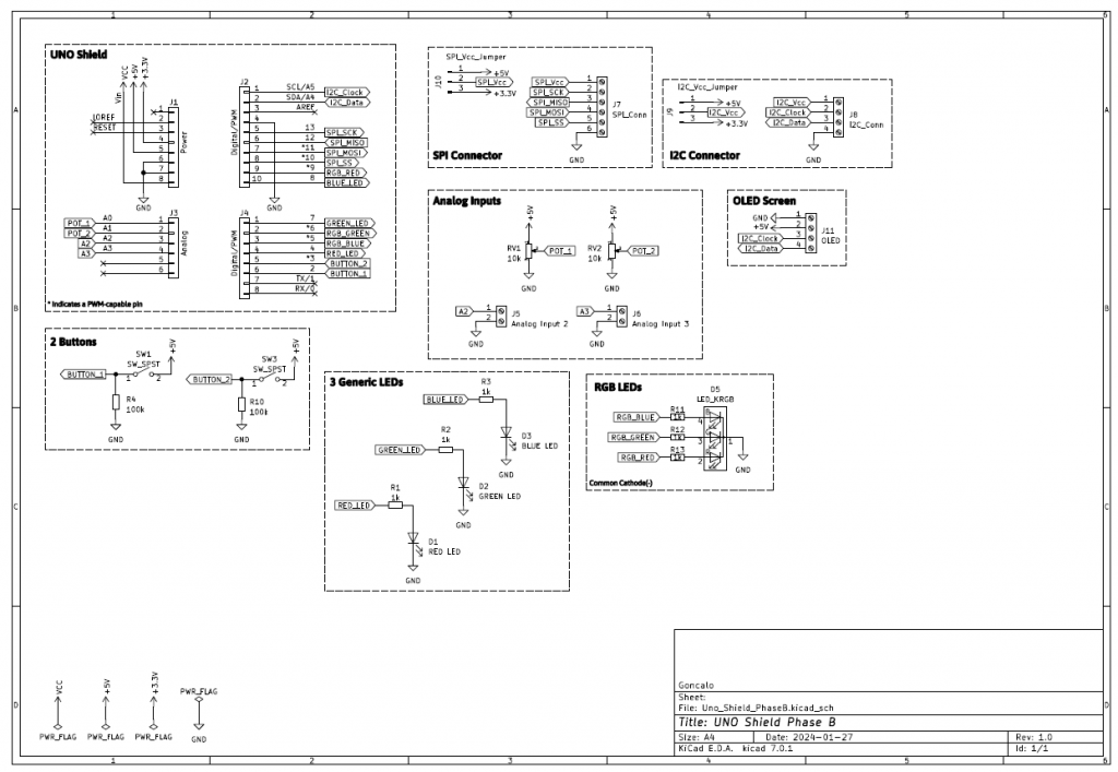
With that in mind, we have the following general block diagram:
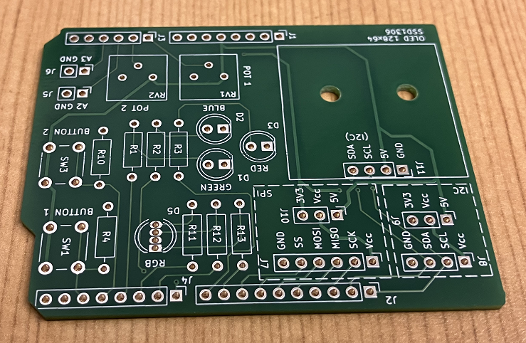
- 3 LEDs (red, green, blue)
- 1 RGB LED
- 2 buttons
- 1 OLED screen
- 2 potentiometers
- 2 analog inputs
- 1 SPI connector with 3.3V or 5V selector
- 1 I2C connector with 3.3V or 5V selector
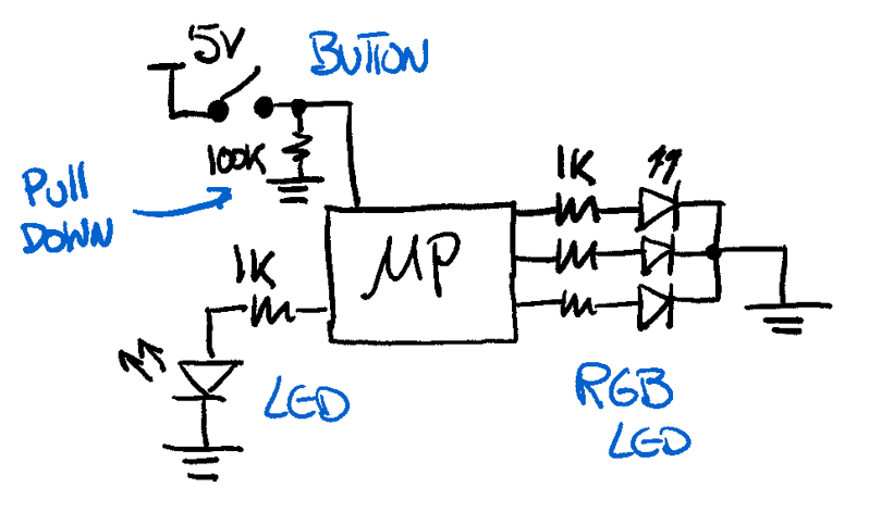
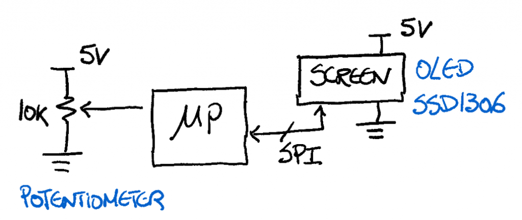
Below you have examples of schematics for some of the blocks.
Prototype Stage
Photos will be uploaded soon...
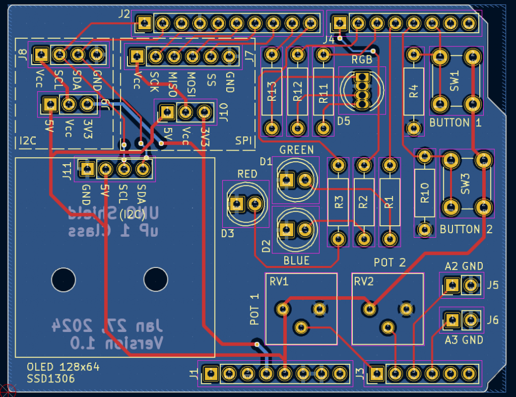
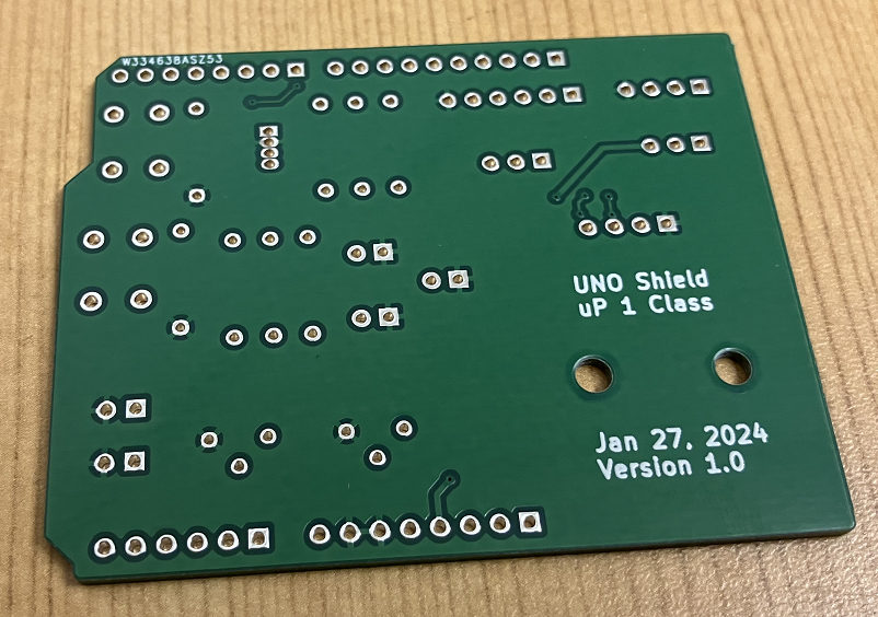
PCB Design
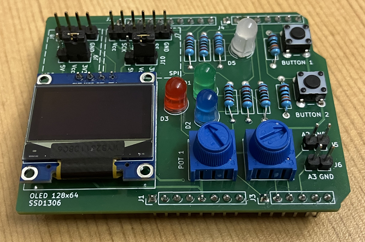
Assemble Stage
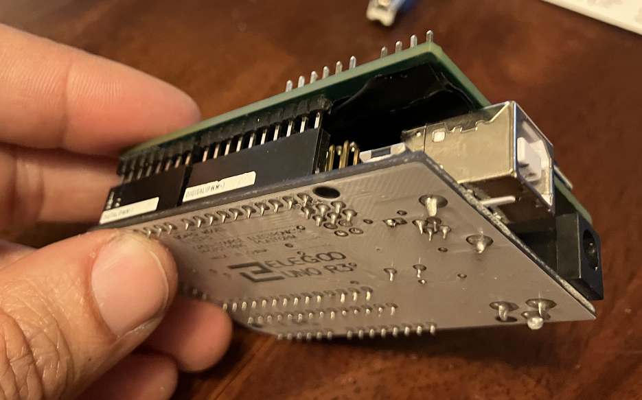
The boards were manufactured by PCBWay
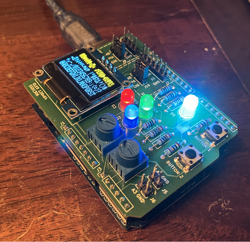
Assembled in house.
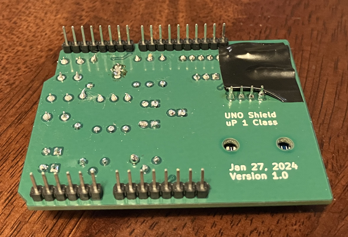
Quick Note: unfortunately, during the design stage I didn't notice that the I2C connector on the shield would be on top and possibly in contact with the Arduino Uno USB connector. Make sure that you put a piece of electric tape on the shield I2C pins to prevent short circuits between shield and Arduino Uno.
Testing Stage
This section presents the code for two tests that students can upload on the shield to see if everything was soldered properly.
Simple Test
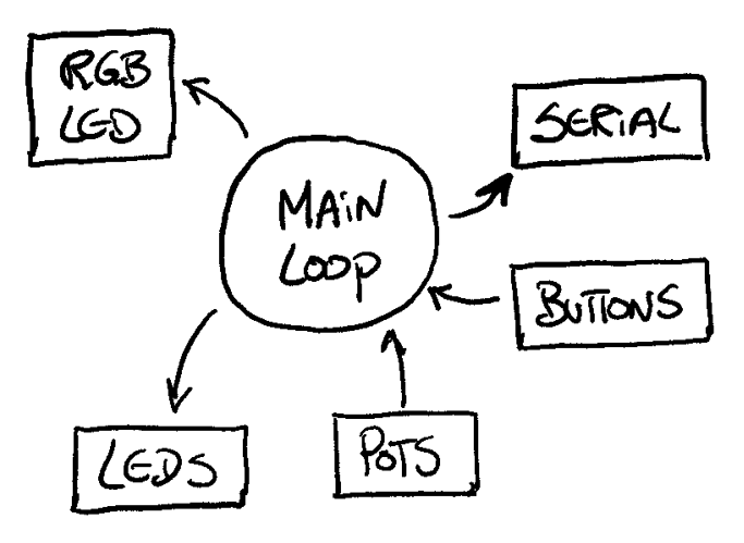
The simple test is straight forward. It tests the 3 LEDs, the RGB LED, the 2 buttons and the 2 potentiometers. The code is done in a sequential way (no concurrency).
/*!
* @brief Simple Test
*
* Date: 2/7/2024
*/
#define RED_LED   8
#define GREEN_LED 4
#define BLUE_LED  7

#define RGB_BLUE  5
#define RGB_RED   9
#define RGB_GREEN 6

#define BUTTON_1  2
#define BUTTON_2  3

#define POT_1     A0
#define POT_2     A1

int gPot_1 = 0;
int gPot_2 = 0;

/*!
* @brief Setup Function
*/
void setup() {
  // Initialize LEDs
  pinMode(RED_LED, OUTPUT);
  pinMode(GREEN_LED, OUTPUT);
  pinMode(BLUE_LED, OUTPUT);

  // Initialize RGB LED
  pinMode(RGB_RED, OUTPUT);
  pinMode(RGB_GREEN, OUTPUT);
  pinMode(RGB_BLUE, OUTPUT);

  // Initialize Buttons
  pinMode(BUTTON_1, INPUT);
  pinMode(BUTTON_2, INPUT);

  // Initialize serial port
  Serial.begin(9600);

}

/*!
* @brief Loop Function
*/
void loop() {
  // Flash LEDs at 200ms
  digitalWrite(RED_LED, HIGH);
  digitalWrite(GREEN_LED, HIGH);
  digitalWrite(BLUE_LED, HIGH);
  delay(100);
  digitalWrite(RED_LED, LOW);
  digitalWrite(GREEN_LED, LOW);
  digitalWrite(BLUE_LED, LOW);
  delay(100);

  // Read Potentiometers
  gPot_1 = analogRead(POT_1);  // read the input pin
  gPot_2 = analogRead(POT_2);  // read the input pin

  // Print value over serial
  Serial.print("Val 1: ");
  Serial.print(gPot_1);
  Serial.print(" Val 2: ");
  Serial.println(gPot_2);

  // Read buttons and turn on/off RGB LED
  if(digitalRead(BUTTON_1))
    digitalWrite(RGB_BLUE, HIGH);
  else
    digitalWrite(RGB_BLUE, LOW);

  if(digitalRead(BUTTON_2))
    digitalWrite(RGB_RED, HIGH);
  else
    digitalWrite(RGB_RED, LOW);

}
gif
Advance Test
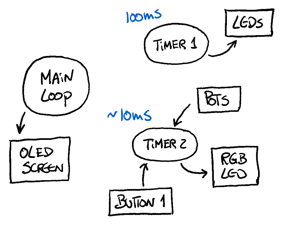
The advance test, includes the OLED screen and implements timers and interrupt routines to enable concurrency between different actions.
/*!
* @brief Advance Test
*
* Date: 2/7/2024
*/
#include <SPI.h>
#include <Wire.h>
#include <Adafruit_GFX.h>
#include <Adafruit_SSD1306.h>

#define SCREEN_WIDTH 128 // OLED display width, in pixels
#define SCREEN_HEIGHT 32 // OLED display height, in pixels

// Declaration for an SSD1306 display connected to I2C (SDA, SCL pins)
#define OLED_RESET     -1 // Reset pin # (or -1 if sharing Arduino reset pin)
#define SCREEN_ADDRESS 0x3C ///< See datasheet for Address; 0x3D for 128x64, 0x3C for 128x32
Adafruit_SSD1306 display(SCREEN_WIDTH, SCREEN_HEIGHT, &Wire, OLED_RESET);

#define RED_LED   8
#define GREEN_LED 4
#define BLUE_LED  7

#define RGB_BLUE  5
#define RGB_RED   9
#define RGB_GREEN 6

#define BUTTON_1  2
#define BUTTON_2  3

#define POT_1     A0
#define POT_2     A1

#define TIMER1_COMPARE_VALUE  6250  // 100ms
#define TIMER2_COMPARE_VALUE  156  // 156.25 rounded to 156 -> a bit less than 10ms

char gISRFlag1 = 0;

int gPot_1 = 0;
int gPot_2 = 0;

int pwmValue_1 = 0;
int pwmValue_2 = 0;

/*!
* @brief Setup Function
*/
void setup() {
  // Initialize LEDs
  pinMode(RED_LED, OUTPUT);
  pinMode(GREEN_LED, OUTPUT);
  pinMode(BLUE_LED, OUTPUT);

  // Initialize RGB LED
  pinMode(RGB_RED, OUTPUT);
  pinMode(RGB_GREEN, OUTPUT);
  pinMode(RGB_BLUE, OUTPUT);

  // Initialize Buttons
  pinMode(BUTTON_1, INPUT);
  pinMode(BUTTON_2, INPUT);

  // Initialize Potentiometers
  pinMode(POT_1, INPUT);
  pinMode(POT_2, INPUT);

  // TASK 1
  // Initialize Timer1 (16bit)
  // Speed of Timer1 = 16MHz/256 = 62.5kHz
  noInterrupts();
  TCCR1A = 0;
  TCCR1B = 0;
  OCR1A = TIMER1_COMPARE_VALUE;  // compare match register
  TCCR1B |= (1<<WGM12);  // CTC mode
  // Start Timer by setting the prescaler
  TCCR1B |= (1<<CS12);  // 256 prescaler
  TIMSK1 |= (1<<OCIE1A);  // enable timer compare interrupt
  //interrupts();

  // TASK 2
  // Initialize Timer2 (8bit)
  // Speed of Timer1 = 16MHz/1024 = 15.625kHz
  //noInterrupts();
  TCCR2A = 0;
  TCCR2B = 0;
  OCR2A = TIMER2_COMPARE_VALUE;  // compare match register
  TCCR2A |= (1<<WGM21);  // CTC mode
  // Start Timer by setting the prescaler
  TCCR2B |= (1<<CS22) | (1<<CS21) | (1<<CS20);  // 1024 prescaler
  TIMSK2 |= (1<<OCIE2A);  // enable timer compare interrupt
  interrupts();

  // SSD1306_SWITCHCAPVCC = generate display voltage from 3.3V internally
  if(!display.begin(SSD1306_SWITCHCAPVCC, SCREEN_ADDRESS)) {
    //Serial.println(F("SSD1306 allocation failed"));
    for(;;); // Don't proceed, loop forever
  }

  // Show initial display buffer contents on the screen --
  // the library initializes this with an Adafruit splash screen.
  display.display();
  delay(2000); // Pause for 2 seconds

  // Clear the buffer
  display.clearDisplay();

}

/*!
* @brief Timer1 ISR (TASK 1)
*/
ISR(TIMER1_COMPA_vect)
{
  // toggle gFlag
  gISRFlag1 = ~gISRFlag1;

  // toggle LEDs
  if(gISRFlag1)
  {
    digitalWrite(RED_LED, HIGH);
    digitalWrite(GREEN_LED, HIGH);
    digitalWrite(BLUE_LED, HIGH);
  }
  else{
    digitalWrite(RED_LED, LOW);
    digitalWrite(GREEN_LED, LOW);
    digitalWrite(BLUE_LED, LOW);
  }
}

/*!
* @brief Timer2 ISR (TASK 2)
*/
ISR(TIMER2_COMPA_vect)
{
  // Read Pot and set RGB LED PWM value
  gPot_1 = analogRead(POT_1);  // read the input pin
  pwmValue_1 = map(gPot_1, 0, 1023, 0, 255);
  analogWrite(RGB_BLUE, pwmValue_1);

  gPot_2 = analogRead(POT_2);  // read the input pin
  pwmValue_2 = map(gPot_2, 0, 1023, 0, 255);
  analogWrite(RGB_GREEN, pwmValue_2);

  if(digitalRead(BUTTON_1))
    digitalWrite(RGB_RED, HIGH);
  else
    digitalWrite(RGB_RED, LOW);
}

/*!
* @brief Loop Function
*/
void loop() {
  // Render OLED images
  testscrolltext();
  testdrawstyles();
  testdrawchar();
}

void testdrawchar(void) {
  display.clearDisplay();

  display.setTextSize(1);      // Normal 1:1 pixel scale
  display.setTextColor(SSD1306_WHITE); // Draw white text
  display.setCursor(0, 0);     // Start at top-left corner
  display.cp437(true);         // Use full 256 char 'Code Page 437' font

  // Not all the characters will fit on the display. This is normal.
  // Library will draw what it can and the rest will be clipped.
  for(int16_t i=0; i<256; i++) {
    if(i == '\n') display.write(' ');
    else          display.write(i);
  }

  display.display();
  delay(2000);
}

void testdrawstyles(void) {
  display.clearDisplay();

  display.setTextSize(1);             // Normal 1:1 pixel scale
  display.setTextColor(SSD1306_WHITE);        // Draw white text
  display.setCursor(0,0);             // Start at top-left corner
  display.println(F("Hello, world!"));

  display.setTextColor(SSD1306_BLACK, SSD1306_WHITE); // Draw 'inverse' text
  display.println(3.141592);

  display.setTextSize(2);             // Draw 2X-scale text
  display.setTextColor(SSD1306_WHITE);
  display.print(F("0x")); display.println(0xDEADBEEF, HEX);

  display.display();
  delay(2000);
}

void testscrolltext(void) {
  display.clearDisplay();

  display.setTextSize(2); // Draw 2X-scale text
  display.setTextColor(SSD1306_WHITE);
  display.setCursor(10, 0);
  display.println(F("Hello World!"));
  display.display();      // Show initial text
  delay(100);

  // Scroll in various directions, pausing in-between:
  display.startscrollright(0x00, 0x0F);
  delay(2000);
  display.stopscroll();
  delay(1000);
  display.startscrollleft(0x00, 0x0F);
  delay(2000);
  display.stopscroll();
  delay(1000);
  display.startscrolldiagright(0x00, 0x07);
  delay(2000);
  display.startscrolldiagleft(0x00, 0x07);
  delay(2000);
  display.stopscroll();
  delay(1000);
}
Students Phase B Boards
Below you can find the boards soldered by students in the Microprocessors Class 2023/2024. Overall, 15 boards were soldered and tested accordingly.
Photos will be uploaded soon...
GitHub Repository
References
None for this project.
Sponsor