TAoE – Chapter 1
Solutions
For the majority of the answers in this chapter I will be using this concept of tools to represent certain circuit analysis techniques. The reason behind this approach is because when solving circuits there are several ways to get to the same answer by using different concepts (or tools). Which way is the correct way? The one that you understand as long as the answer is correct.
- The fundamental tools are Ohm's Law, Kirchhoff's Laws (KCL and KVL), equivalent resistance and power.
- Circuit reduction and source transformation build from these fundamental tools.
- Then Mesh, Nodal, Thevenin, Norton and superposition are more advance tools that use the fundamental tools in a sequence of steps.
- I highly recommend reading about these concepts before tackling some of the problems on this Chapter. Digilent website has a good and free resource (Real Analog: Circuits 1) that you can use.

Outline
1.2 Voltage, current and resistance
- Exercise 1.1
- Exercise 1.2
- Exercise 1.3
- Exercise 1.4
- Exercise 1.5
- Exercise 1.6
- Exercise 1.7
- Exercise 1.8
- Exercise 1.9
- Exercise 1.10
- Exercise 1.11
1.3 Signals
- Exercise 1.12
- Exercise 1.13
1.4 Capacitors and ac circuits
- Exercise 1.14
- Exercise 1.15
- Exercise 1.16
- Exercise 1.17
- Exercise 1.18
1.5 Inductors and transformers
- Exercise 1.19
1.6 Diodes and diode circuits
- Exercise 1.20
- Exercise 1.21
- Exercise 1.22
1.7 Impedance and reactance
- Exercise 1.23
- Exercise 1.24
- Exercise 1.25
- Exercise 1.26
- Exercise 1.27
- Exercise 1.28
- Exercise 1.29
- Exercise 1.30
- Exercise 1.31
- Exercise 1.32
- Exercise 1.33
- Exercise 1.34
- Exercise 1.35
1.9 Other passive components
- Exercise 1.36
Additional Exercises for Chapter 1
- Exercise 1.37
- Exercise 1.38
- Exercise 1.39
- Exercise 1.40
- Exercise 1.41
- Exercise 1.42
- Exercise 1.43
- Exercise 1.44
Exercise 1.1
For this exercise we can use the equivalent resistance equations in page 5.
R=R_1+R_2 \;\;\;\;\; \text{(Eq. 1.3)}R=\frac{R_1R_2}{R_1+R_2} \;\;\;\;\; \text{(Eq. 1.4)}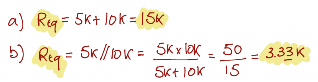
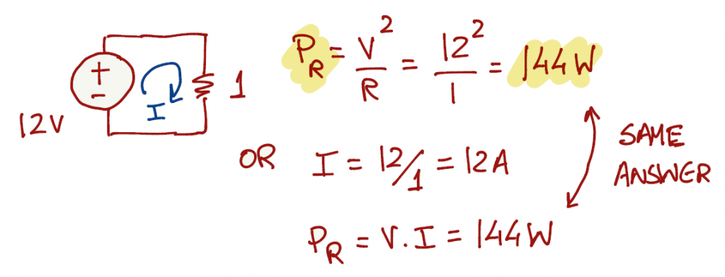
Exercise 1.2
On page 6, section C, you can find the equation of power dissipation by a resistor and respective equivalent forms. When questions are descriptive and don't provide a schematic, it helps if we design the respective schematic in order to understand which tool(s) can be use to solve the exercise.
- Option 1: since the voltage source is in parallel with the resistor, the resistor sees the same voltage (12V).
- Option 2: apply ohm's law and get the current in the circuit and then apply the power equation.
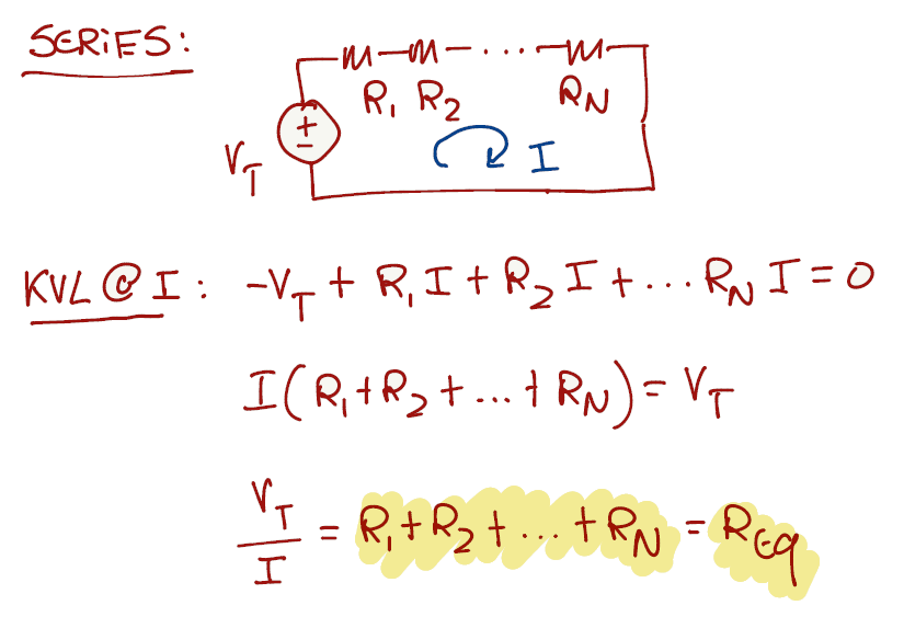
Exercise 1.3
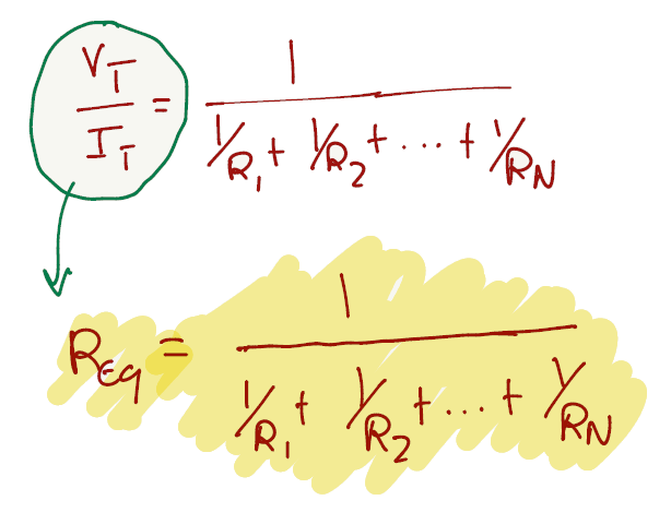
To prove the formula for series, we can use KVL around a loop of components in series and apply ohm's law on the final equation to get the equivalent resistance.
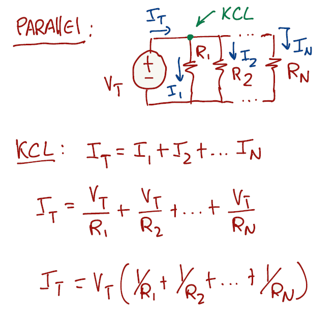
To prove the formula for parallel, we can use KCL on a node and apply ohm's law on the equation to get the equivalent resistance.
Exercise 1.4
Is proven in Exercise 1.3
Exercise 1.5
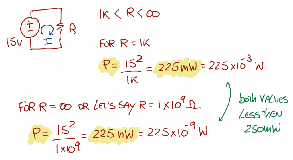
Let's start the exercise by expression a quarter of a watt in mW.
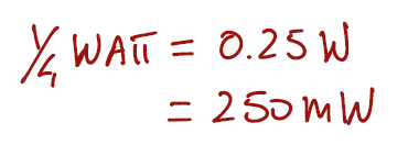
We need to evaluate the circuit for all R's greater than 1kΩ. For R = 1kΩ the power is 225 mW and for R = 1GΩ the power is 0.000225 mW. Both values are smaller than 250 mW.
Exercise 1.6
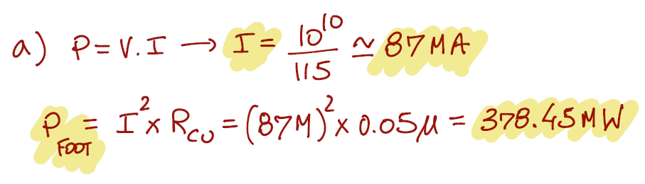
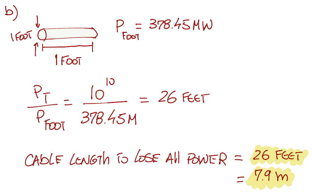
Some exercises benefit by writing down all the available information before tackling the solution. For this particular case, if you are not familiar with the imperial system (feet or inches), we can convert the answer to the metric system (meters, centimeters or millimeters).
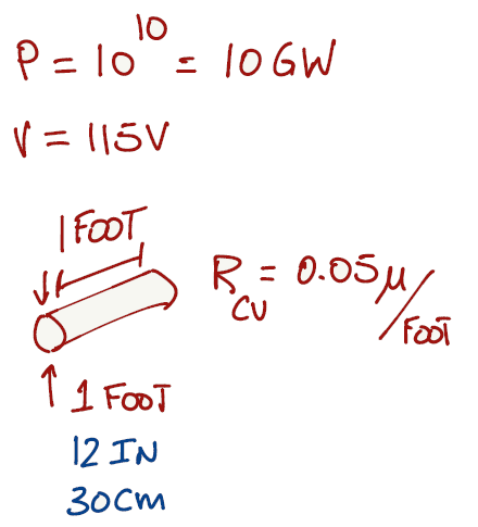
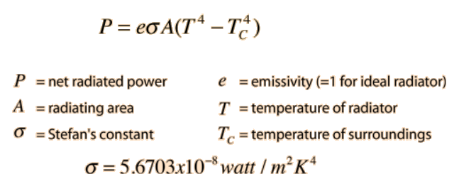
There are 4 different mechanism of transferring heat in an object: conduction, convection, radiation and vaporization (Link). Thermal radiation is energy transfer by the emission of electromagnetic waves which carry energy away from the emitting object. This is the case of the cable, and this thermal radiation generates heat.
The relationship governing the net radiation from hot objects is called the Stefan-Boltzmann law:
We can write the Stefan-Boltzmann law in terms of absolute temperature (T) instead of considering the hot object radiating energy to its cooler surroundings at temperature Tc. We can also consider an ideal radiator and set e = 1:
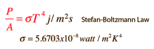
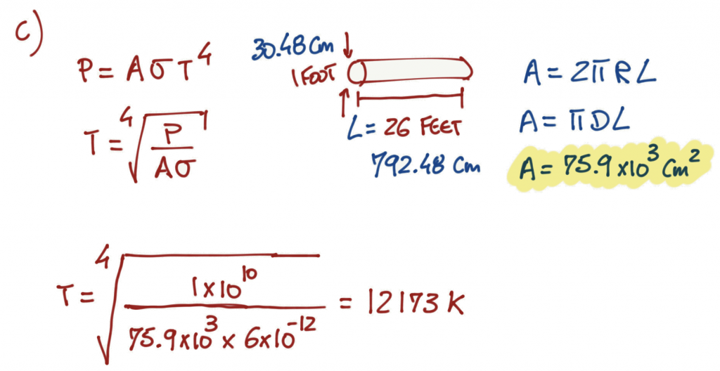
As a point of reference, the sun radiates at around 5800K and a hot campfire at 800K. The cable temperature for this example is indeed preposterous.
To reduce the heat in a cable, we can apply two solutions:
Solution 1
- if we increase the voltage from 115V to 115kV, and since the power is the same, the current that flows in the wire is going to be less.
- If the current is less, the power lost per foot is going to be reduced significantly.
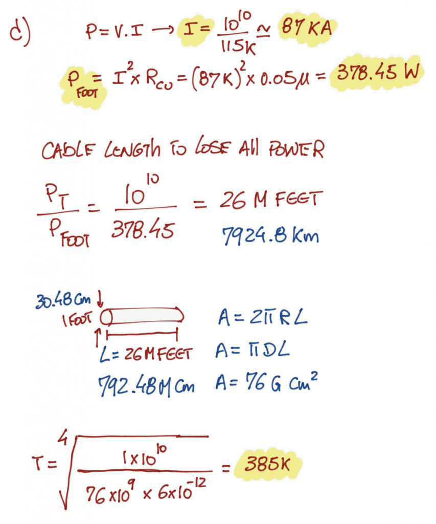
The cable length is now 1000000 times longer and the cable heat is reduced significantly. As a point of reference, the heat is now around 106 degrees Celsius (223 Fahrenheit).
Solution 2
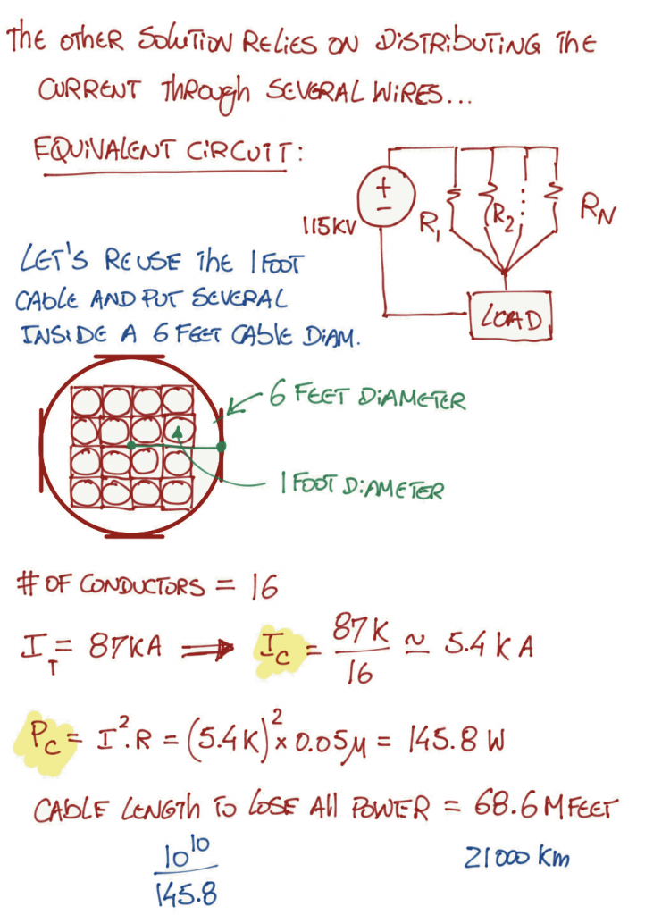
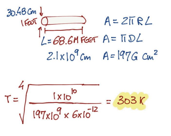
With this techniques, we reduce the temperature even more, close to 29 degrees Celsius (84 Fahrenheit).
Exercise 1.7
Remember that designing a schematic can help visualize the problem that your are trying to solve.
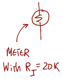
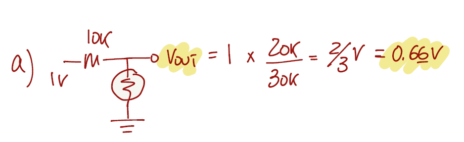
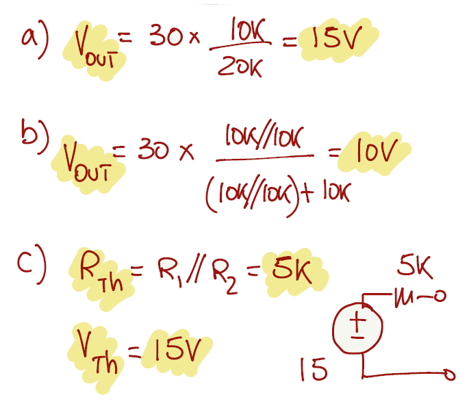
For the first question the voltage source as an internal resistance of 10kΩ and it is connected in series with the meter. Since all the components are connected in series, we can apply the voltage divider equation (from page 7).
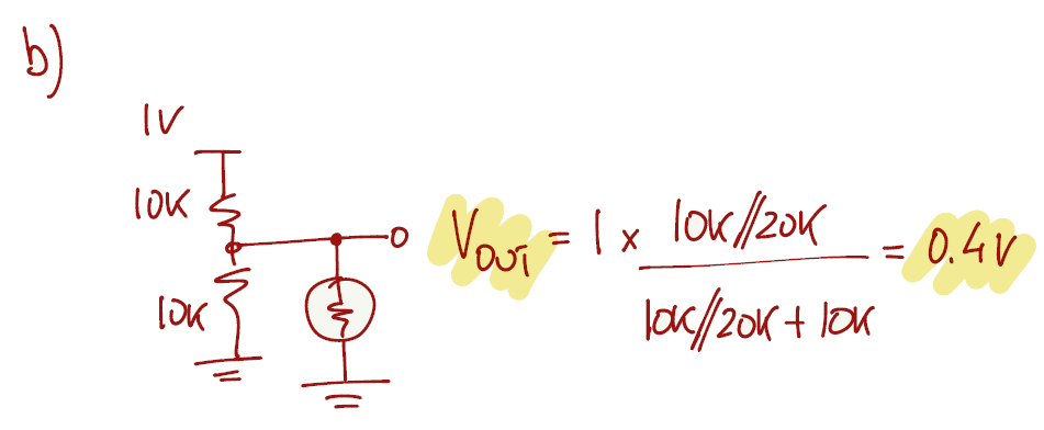
The voltage divider can still be used to answer b), however the resistor R2 from the voltage divider equation is now the parallel of 10kΩ with 20kΩ, changing the output voltage accordingly.
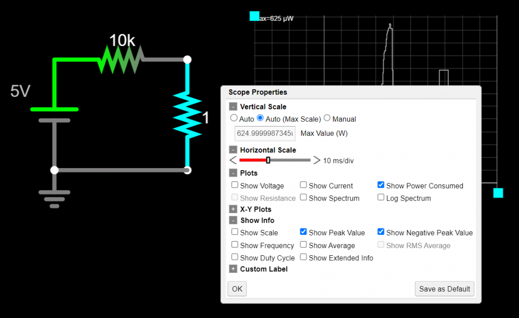
We have been solving the exercises with hand calculations but we can also simulate the circuits to get a better understanding of our solutions. There are a lot of different circuit simulators that you can use. Falstad is free and does a wonderful job with the visualization of the current and voltages in your circuits, and we can also share the circuits by exporting a link.
Falstad link for this exercise.
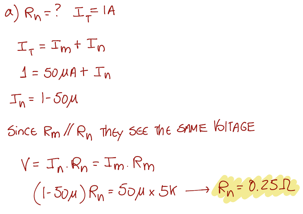
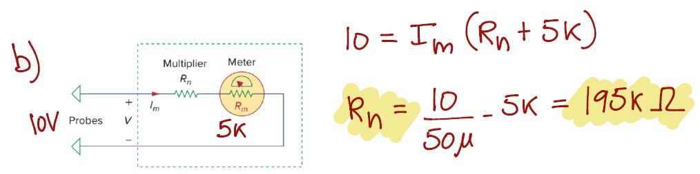
Exercise 1.8
We will start by designing what the exercise is asking for:
Exercise 1.9
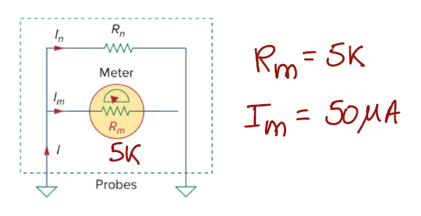
This exercise can be a bit confusing at first, but let's design the schematic for a DMM in voltage mode (voltmeter). The Rn resistance will be ignored for this exercise because we don't need to have the voltmeter changing ranges. RL is representing the "leakage" resistance and Rm is the DMM internal resistance for the 2V dc range. The available dc source can go up to 10V.
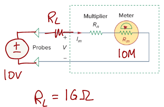
Since all elements in this circuit are connected in series, we can apply the voltage divider equation (from page 7) to get a reading from the DMM meter. If we vary the input voltage source from 0.1V to 10V we will be able to read values from 0.1V to 0.001v
V_{out}=V_{in}*\frac{R_m}{R_m+R_L}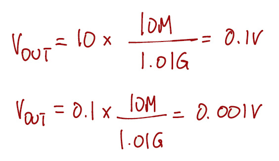
If the meter is analog, the needle will not move that much for that range of values.
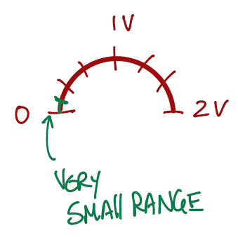
However, the problem is asking a different question. The problem is asking how accurately can we measure a leakage resistance. To answer that question, we need to rewrite the voltage divider in terms of RL.
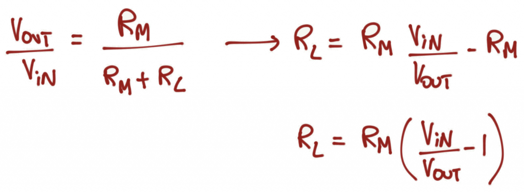
With the equation written in this form we have the DMM reading the value of RL, and we can control the range of values by varying the input dc voltage source accordingly.
Let's use Desmos to visualize this (Link). On the animation below, varying Vin represents changing the resolution of the reading, and varying Vout represents changing the output voltage reading in order to see what RL is connected in the circuit.
We can see that for Vin = 10V, we can measure RL's from 990GΩ to 40GΩ. For Vin = 2.1V, we can measure RL's from 200GΩ to 500kΩ. Vin shouldn't be less than Vout, otherwise you will get negative values of resistance.
Exercise 1.10
For this exercise we keep applying the voltage divider equation (from page 7).
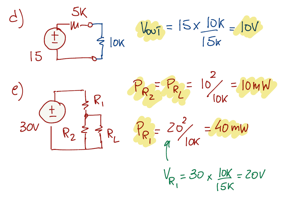
Exercise 1.11
You can find the solution for this exercise in any classic circuits book. It relies on finding when the derivative of the power equation combined with the voltage divider equation is equal to zero with respect to RL.
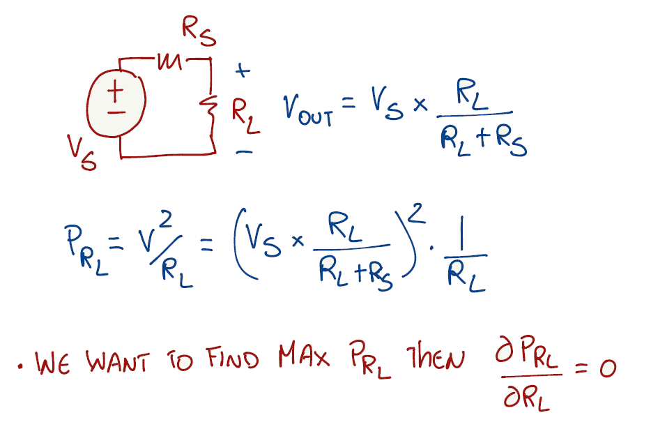
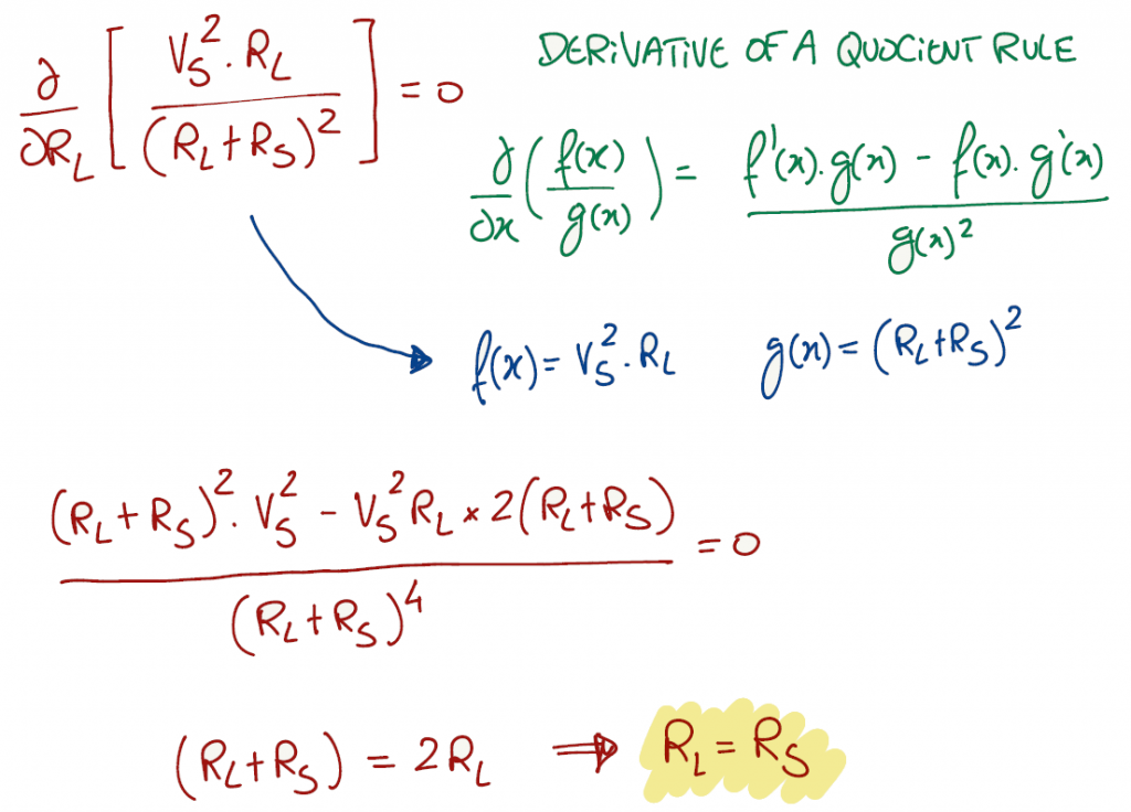
Let's plot the power equation on Desmos and analyze the answer (Link). Notice on the animation below, the power is maximum when RL = Rs no matter how you vary Rs. Varying Vs, the maximum power value changes (with no surprise) but it is still related to RL = Rs.
Falstad link for this exercise
Exercise 1.12
To answer this question we need to rewrite (Eq. 1.11) and (Eq. 1.12) on page 15 in the following way:
dB=10*log_{10}(\frac{P_2}{P_1}) \to \frac{P_2}{P_1}=10^{\frac{dB}{10}} \;\;\;\; (Eq. 1.11)dB=20*log_{10}(\frac{A_2}{A_1}) \to \frac{A_2}{A_1}=10^{\frac{dB}{20}} \;\;\;\; (Eq. 1.12)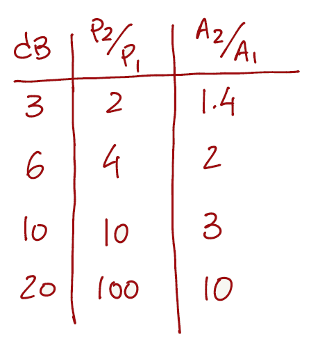
Exercise 1.13
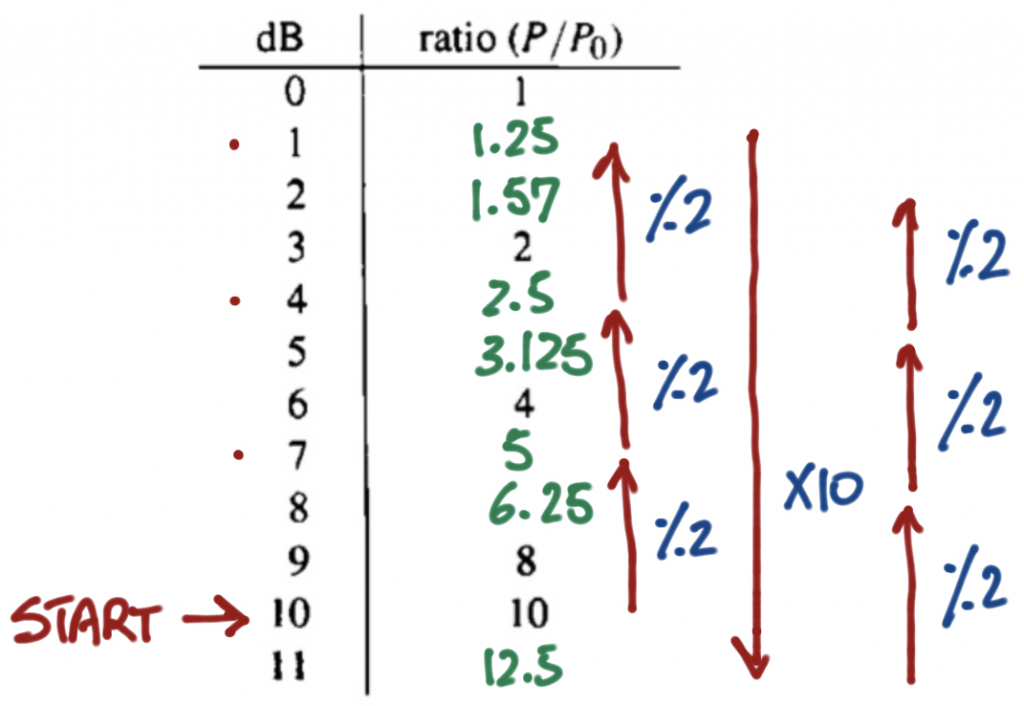
Notice from the previous exercise that increments of 3 dB correspond to doubling the ratio P2/P1 and conversely decrements of 3 dB correspond to divide the ratio P2/P1 by 2.
Another aspect to notice, but not that obvious, adding 10 dB corresponds to multiply the ratio P2/P1 by 10.
With that in mind, starting at 10 dB we can complete the table without using a calculator.
Exercise 1.14 (TODO)
soon...
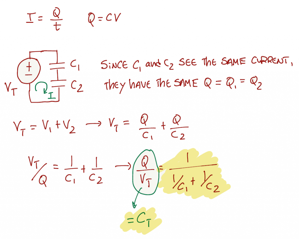
Exercise 1.15
Using (Eq. 1.13) on page 18
Exercise 1.16
Using (Eq. 1.22) on page 22
t=RC*log_e(\frac{V_t}{V_t - V_{out}}) \;\;\;\; (Eq. 1.22)The rise time is equal to (t at 90%) - (t at 10%)

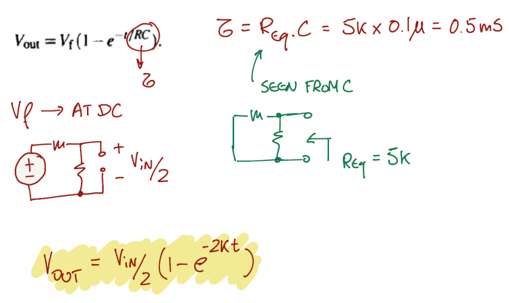
Exercise 1.17
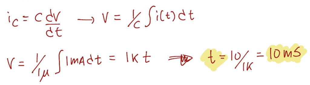
Exercise 1.18
Using (Eq. 1.15)
Exercise 1.19 (TODO)
soon...
Exercise 1.20 (TODO)
soon...
Exercise 1.21 (TODO)
soon...
Exercise 1.22
It is important to remember the statement on page 31 (section 1.6.1):
"The diode's arrow (the anode terminal) points in the direction of forward current. For example, if the diode is in a circuit in which a current of 10mA is flowing from anode to cathode, then the anode is approximately 0.6V more positive than the cathode; this is called the "forward voltage drop"."
Falstad link for this exercise
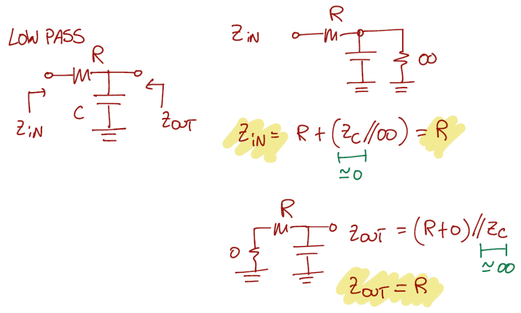
Exercise 1.23
This exercise is asking to show if the statement on page 44 is correct:
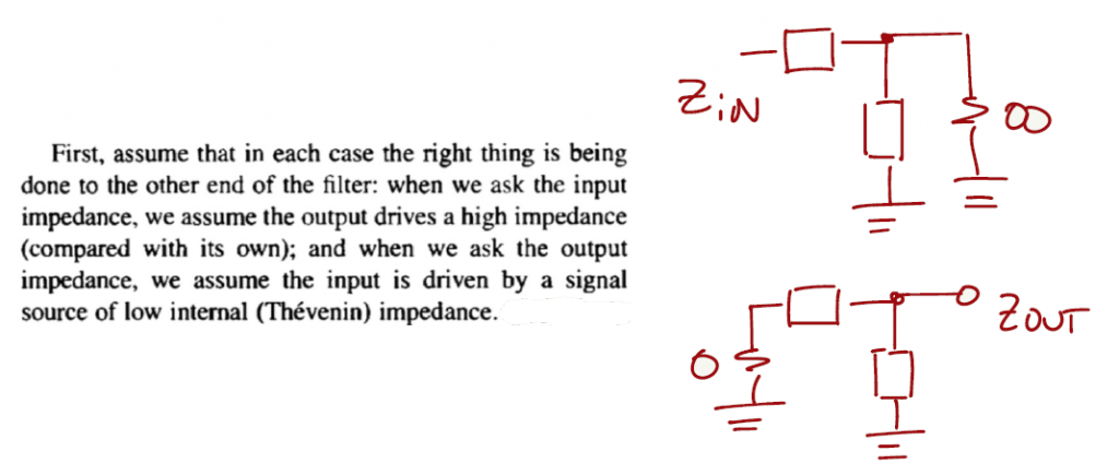
"What we want to know, then, are the input and output impedances of the two RC filters (lowpass and highpass). This sounds complicated, because there are four impedances, and they all vary with frequency. However, if you ask the question the right away, the answer is simple, and the same in all cases!"
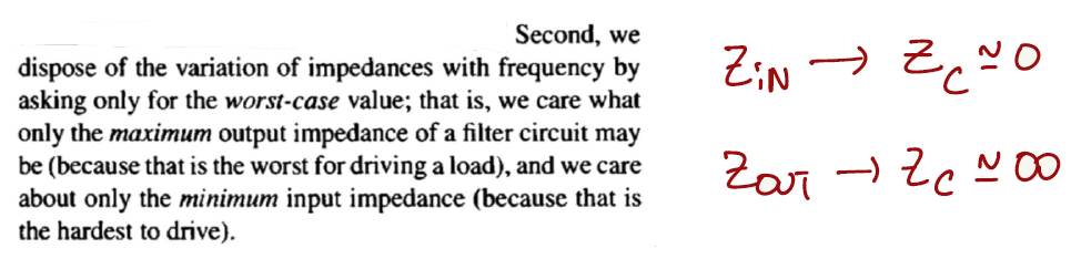
Before solving this exercise, the text on page 44 provides some direction:
Let's then solve the exercise and start with the low pass filter:
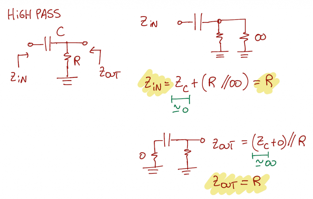
Then the answer for a high pass filter:
Exercise 1.24 (TODO)
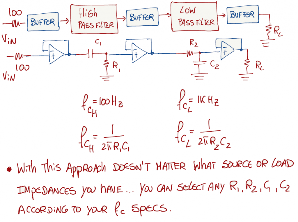
This question is a bit more complex to solve with just the knowledge provided on Chapter 1. The exercise asks to design a two-stage "bandpass" RC filter, where the input signal source has an impedance of 100Ω, what is the worst output impedance, and the minimum recommend load impedance
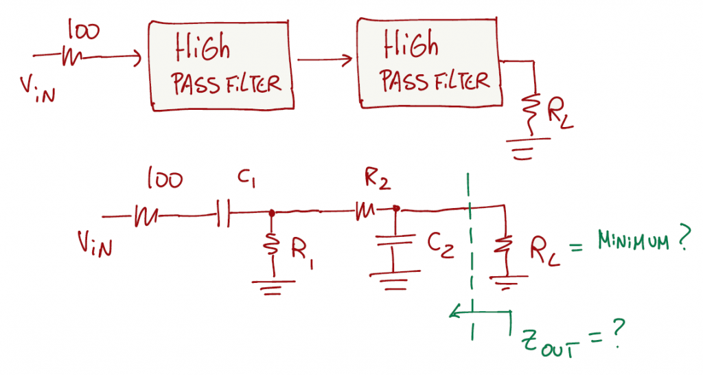
The main goal of this exercise is to show the reader the use of the equation shown on page 49:
f_{3dB}=\frac{1}{2\pi RC}However, it is not that straight forward to just plug the values of the desired frequency in that equation, mainly because the 100Ω and RL are going to act as loads in the circuit. We have to take into account these impedances in the equation.

1) Solution with buffers
If the reader is familiar with Op Amps, in specific the buffer configuration, that will be the "easiest" way to solve this exercise.
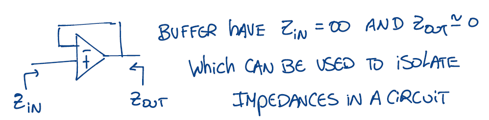
If we add buffers between the filters, the input and output loads, then we can use the equation on page 49 with no problem and select the values of R and C according to the desired cut-off frequency.
2) Solution with no buffers
This solution involves a bit more work.
- Since we have capacitors in the circuit, the equations that we are dealing with have derivatives and are called differential equations.
- Solving differential equations in the time domain is very laborious. However, if we convert the circuit or differential equations to the Laplace domain, it makes it easier to study and analyze the circuit.
- For example, if we don't consider the 100Ω and RL, the equation in the Laplace domain is below.
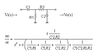
- At this moment, we can use the online filter design tool to find the values of R1, R2, C1, and C2 for the desired cut-off frequencies.
- However, we are still missing including the 100Ω and RL in the equation.
continue...
Exercise 1.25
Using (Eq. 1.13) on page 18
Exercise 1.26 (TODO)
soon...
Exercise 1.27 (TODO)
soon...
Exercise 1.28 (TODO)
soon...
Exercise 1.29 (TODO)
soon...
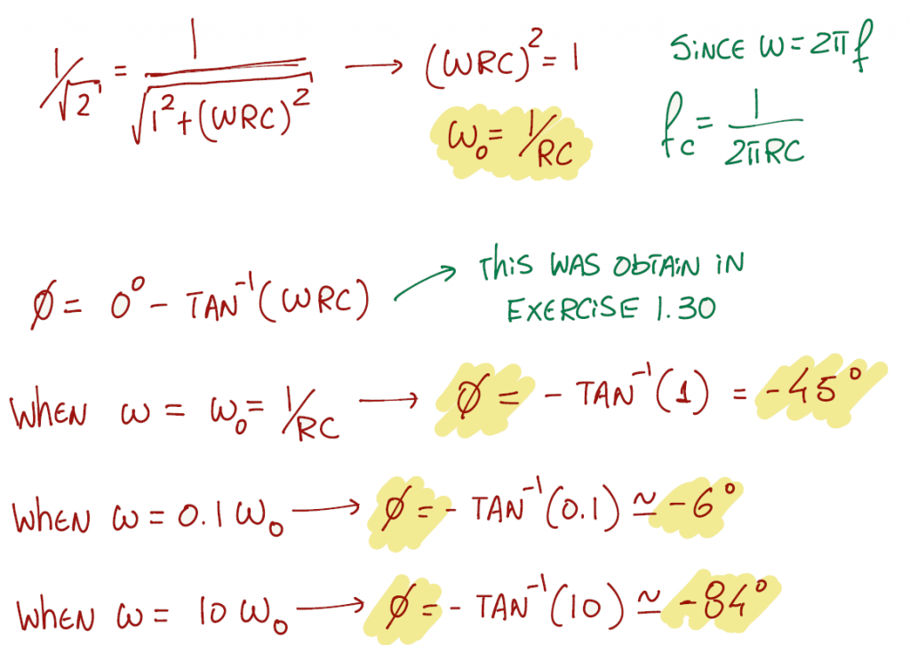
Exercise 1.30
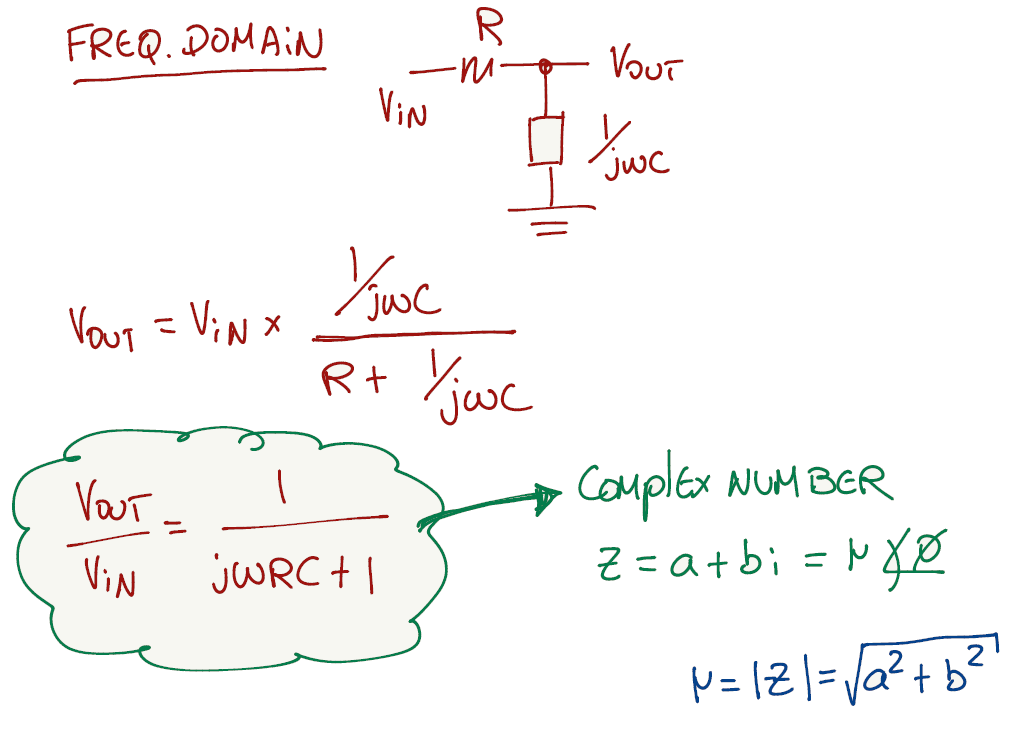
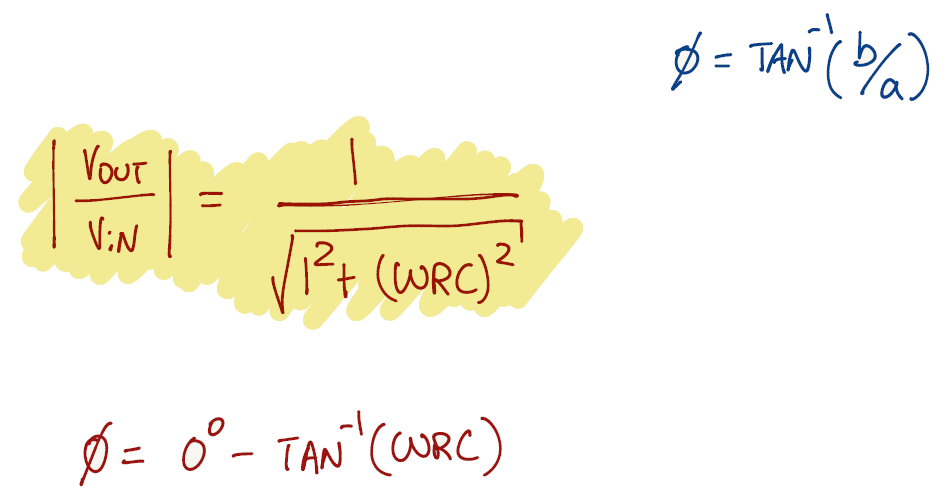
To solve this exercise we need to apply frequency domain analysis. After converting the circuit to the frequency domain, the tools presented at the beginning of this article can be used with no problem. For example, the capacitor and resistor become impedances and we can apply the voltage divider to find the output voltage. Since impedances are complex numbers, a complex number has a magnitude and phase.
Exercise 1.31
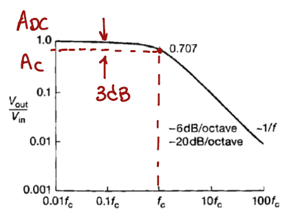
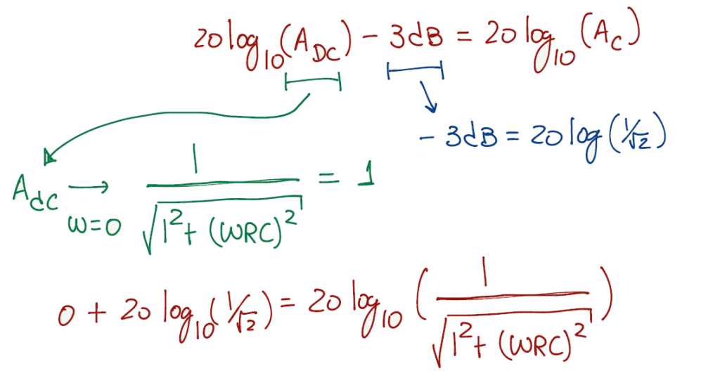
To tackle this problem I think it helps looking at the amplitude frequency response, and write the expression that related the amplitude at DC, with the amplitude a -3 dB's and the 3 dB's. We can't forget that this graph is in log10 scale.
Exercise 1.32 (TODO)
soon...
Exercise 1.33 (TODO)
soon...
Exercise 1.34 (TODO)
soon...
Exercise 1.35
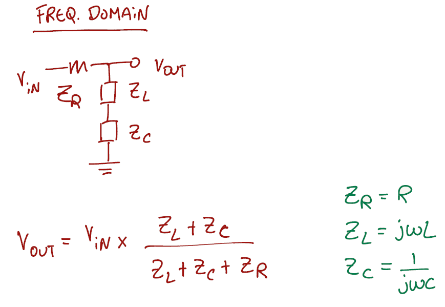
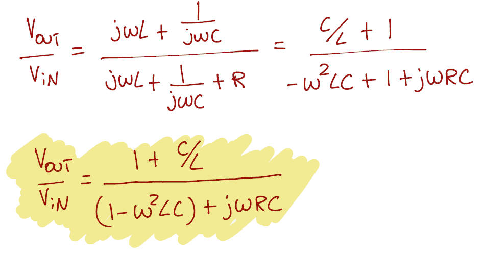
Another exercise that is easier to solve if we convert the circuit to the frequency domain. Then we can apply a voltage divider to get the transfer function of Vout/Vin.
Exercise 1.36
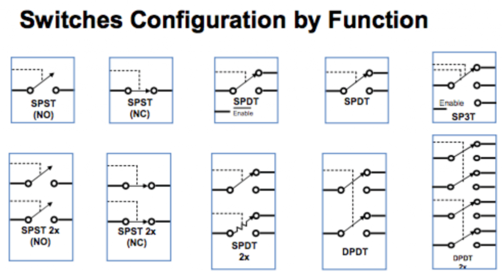
I like to approach this exercise by understanding the DPDT switch first and then combine with the rest of the circuit that has the SPDT switches.
There are 4 types of switches:
- SPST (Single Pole Single Throw)
- SPDT (Single Pole Double Throw)
- DPST (Double Pole Single Throw)
- DPDT (Double Pole Double Throw)
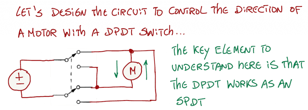
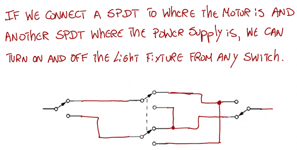
If you want to add more DPDT switches, just apply the same thought process by having the SPDTs at the end of the circuit, and the DPDT's in the middle.
Exercise 1.37
To find the Norton equivalent, we need to find the short circuit current (ISC) and the Norton resistance (RN).
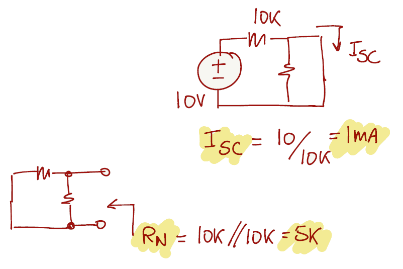
After that, we can connect any desired load resistance.
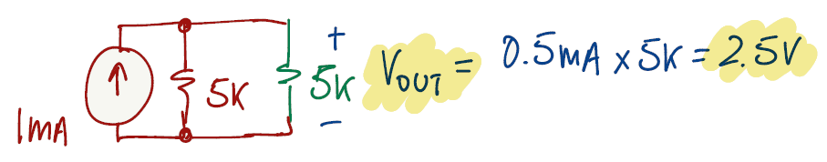
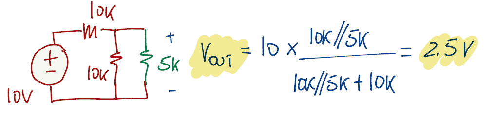
And confirm with the original circuit that we get the same answer.
Exercise 1.38
The exercise asks to find the Thevenin equivalent of the circuit. To find the Thevenin voltage (Vth - also known as open circuit voltage), we can apply ohm's law at the 10kΩ resistor. To find the Thevenin equivalent resistance (Rth), we need to eliminate the current source from the circuit and find the equivalent resistance seen from where you got Vth.
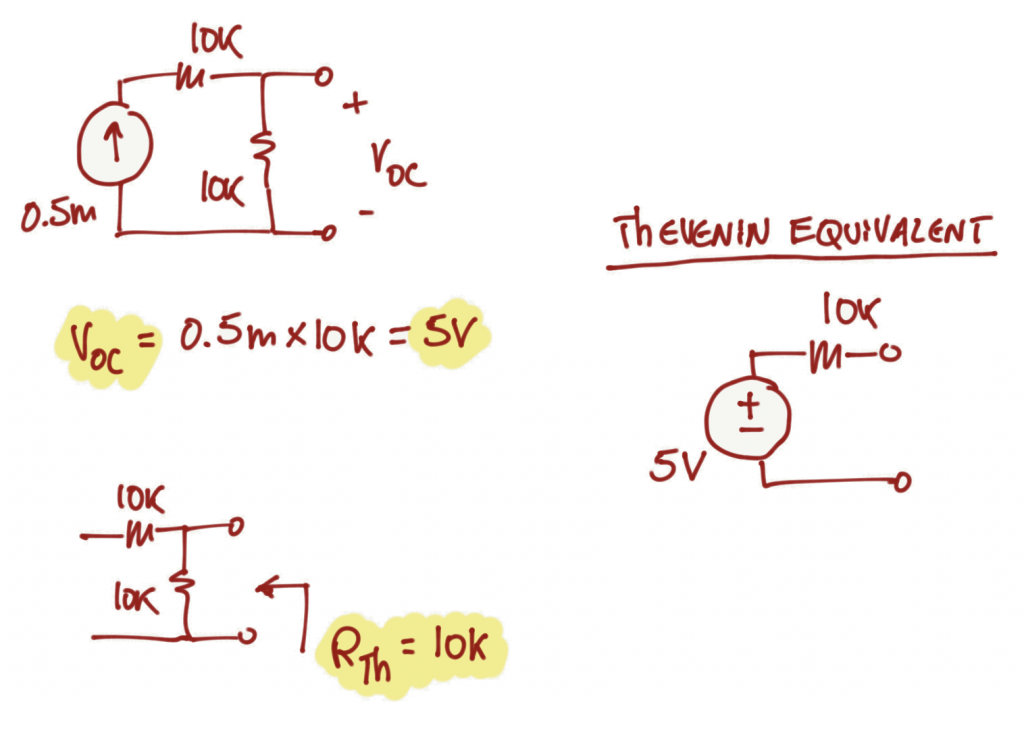
The Thevenin equivalent circuit of this exercise is different from the Thevenin equivalent circuit of Exercise 1.37.
Exercise 1.39 (TODO)
soon...
Exercise 1.40 (TODO)
soon...
Exercise 1.41 (TODO)
soon...
Exercise 1.42 (TODO)
soon...
Exercise 1.43
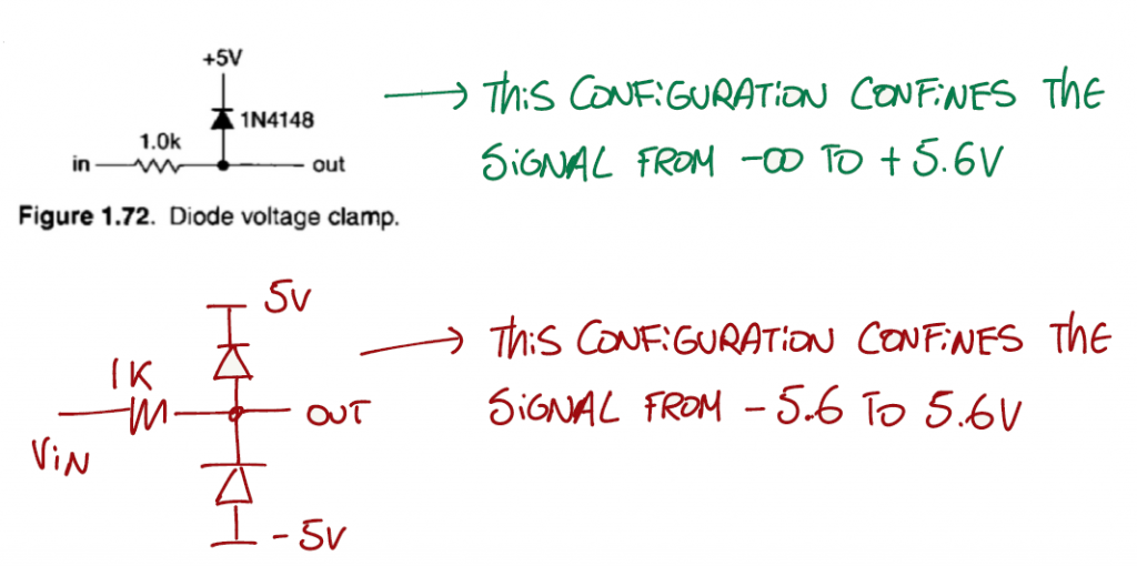
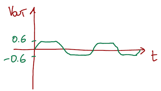
It is important to remember the statement on page 31 (section 1.6.1):
"The diode's arrow (the anode terminal) points in the direction of forward current. For example, if the diode is in a circuit in which a current of 10mA is flowing from anode to cathode, then the anode is approximately 0.6V more positive than the cathode; this is called the "forward voltage drop"."
Since we have two diodes connected with opposite sides, when one is conducting the other one is off, and vice-versa, limiting the output to +/- 0.6V.
Falstad link for this exercise
Exercise 1.44 (TODO)
soon...
References
- [REF 1] "TBD", [Book]