Direction of Current
Another topic of great confusion when analyzing circuits is the assignment of current directions in a circuit. Let's explore this confusion and hopefully by the end of the article you will understand that it doesn't matter which direction you pick as long as you are consistent on applying certain rules during your circuit analysis.
I can tell you in advance that all you need to do is:
- Apply any current directions in your circuit (don't overthink)
- Find all the voltages in your circuit (it doesn't matter which current directions you pick, your analysis will always give you the correct node voltages)
- Finally adjust the direction of the currents according to your node voltages and your current convention (conventional vs electron flow).
Electrons Flow vs Conventional Flow
I am going to start the article with the topic of electron vs conventional flow, because I want the reader to understand that for circuit analysis, it doesn't matter how actually electrons flow in a circuit.
Note: I want to emphasize one more time, that electron or conventional flow doesn't matter only for circuit analysis. For physics purposes, it is important to consider the correct direction of the electrons in a system.
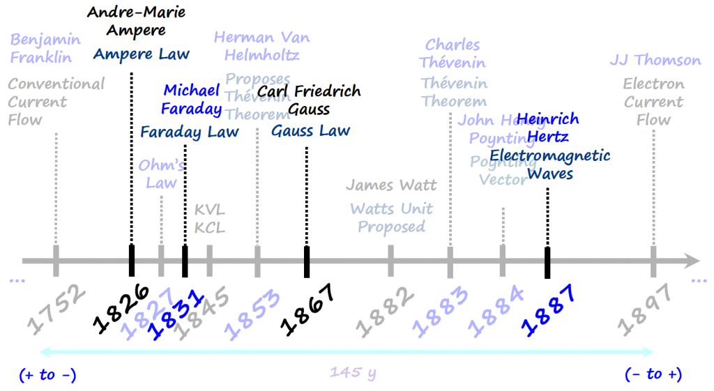
Several experiments done with electricity around the 15's and 16's hundreds lead to the impression that current would flow from positive to negative charges (e.g.: William Gilbert investigation on electrical charging by friction, or Thomas-Francois Dalibard that did the first lightning rod experiment, or even experiments with cells where the cell's carbon electrode behaved in a similar way to fur, and a silver electrode in a similar way to rubber).
However, for some reason Benjamin Franklin around 1752, got famous by his kite experiment and it seems that a lot of literature coined the invention of the conventional flow to Benjamin Franklin. We know that Franklin was not the first one to demonstrate the electrical nature of lightning but for simplicity I am going to use that landmark discovery to highlight the beginning of current convention.
Note: I will update this section if I find a legit resource with more information about this.
It was only around 145 years later that JJ Thomson demonstrated that electrons are actually negatively charged. By this time, however, the convention had been established that electric current ran from the positive terminal to the negative terminal.
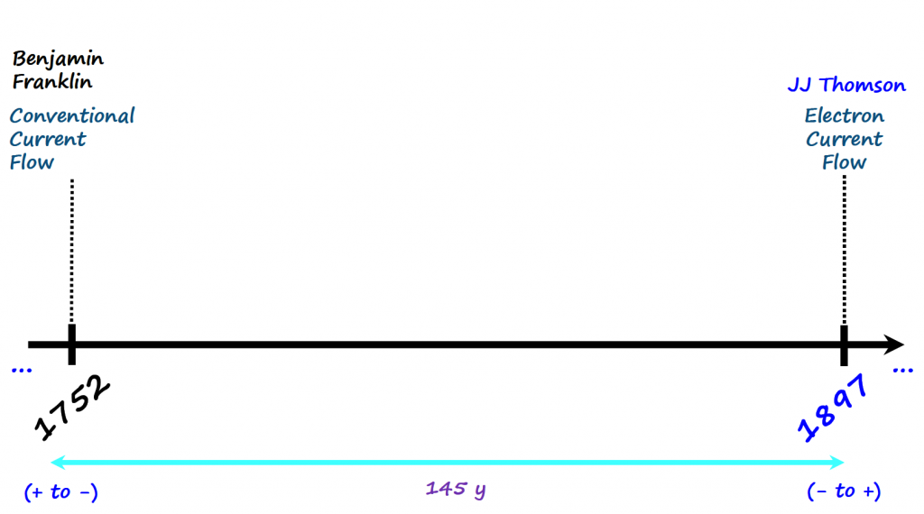
Notice on how all the equations that we are familiar with to analyze circuits were developed before JJ Thomson discovery and considered the conventional current flow (charges move from positive to negative terminal).
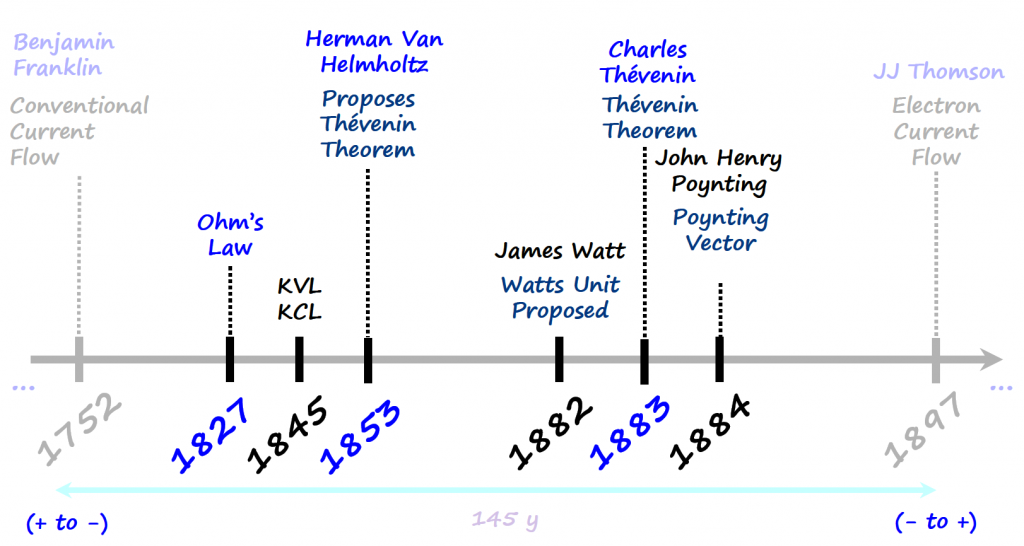
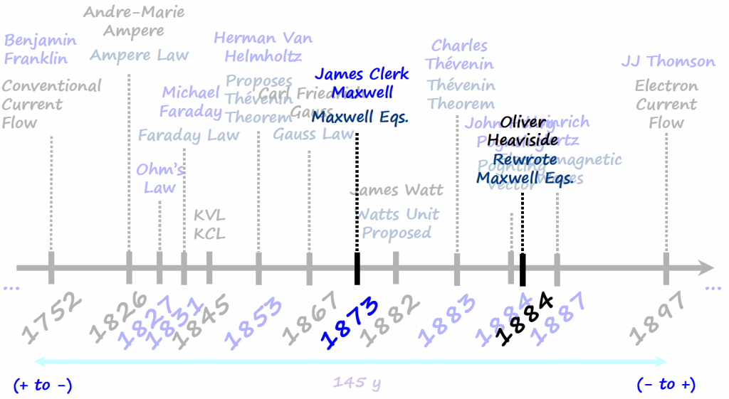
It would have been crazy if JJ Thomson discovery affected all the knowledge developed up to that point. For the rest of this article I will assume conventional flow of electrons , but if the reader wants to consider electron flow, the math and thought process below will be exactly the same.
The Question?
The question is now the following:
- For circuit analysis purposes, when presented with a circuit, which current direction should we select?
Before answering this question, let's go over two rules that you need to apply consistently in order to get the same results independently on how you pick the current direction.
Rule 1 - KCL
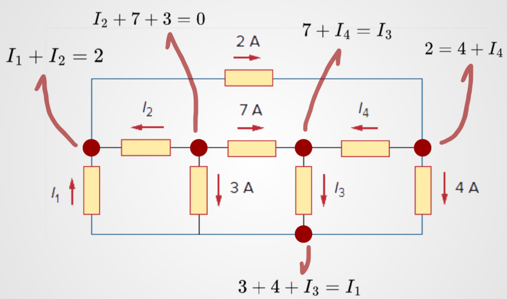
The sum of the currents entering a node is equal to the sum of the current leaving the node. This is known as Kirchhoff's Current Law or KCL.
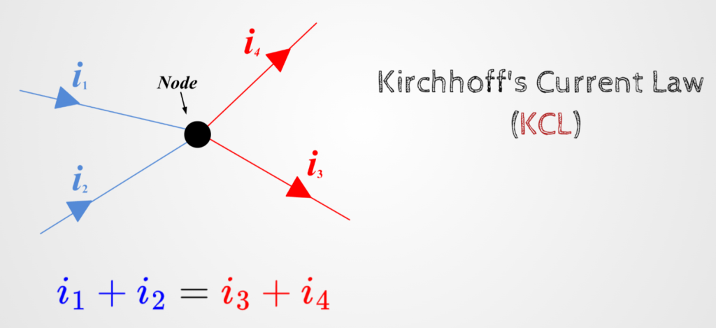
Note: there are some people that are resistant to use KCL because it is a simplification of one of Maxwell's equations (Ampere's Law). I will dive in into this topic in another article, but for now I want the reader to know that is fine to use KCL for what we call Lumped-element Models (Link) and circuits where we don't have external magnetic fields interfering with the circuit.
KCL Example:
Rule 2 - Passive Sign Convention
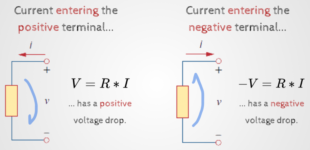
The second rule is related with passive sign convention:
Example:
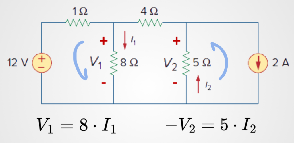
- Consider the circuit below
- What is in red (currents and +/- signs) was picked randomly
- Based on that:
- If the current direction that you pick enters the positive sign, you write ohms law for that particular component with a positive sign
- If the current direction that you pick enters the negative sign, you write ohms law for that particular component with a negative sign
That is it, don't overthink just apply these two rule and you will always get the correct node voltages.
An Example
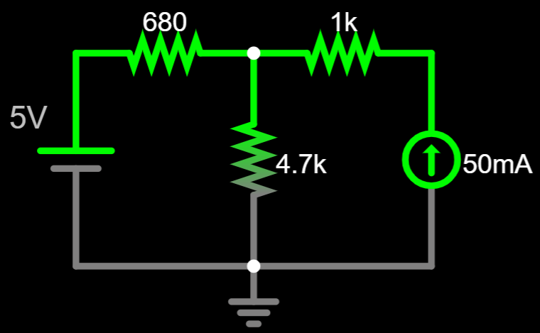
Let's test the rules with this circuit:
I am assigning random current directions and random signs around the resistors.
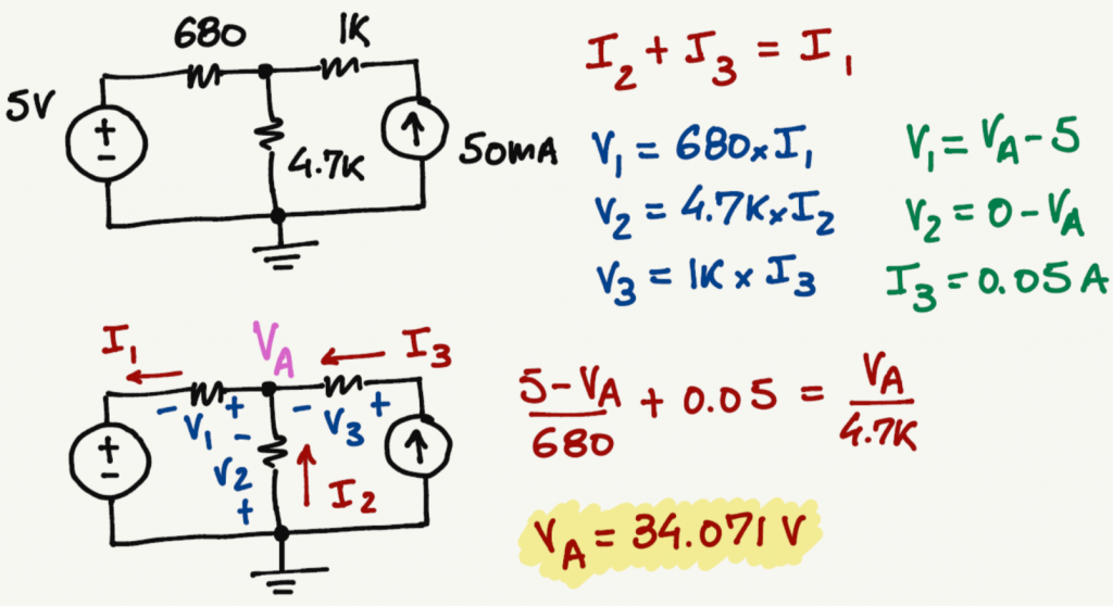
Apply rule 1 and rule 2 to the circuit. I am splitting the circuit in two below, in order to be easier to follow the steps.
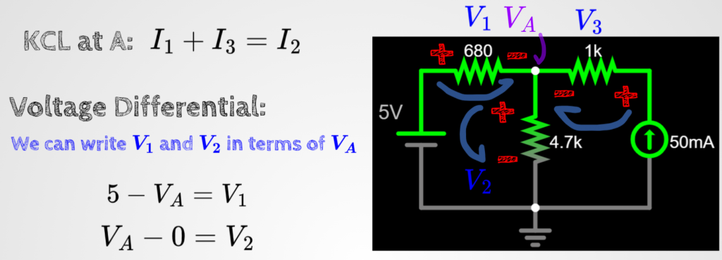
Let's continue the analysis by combining the results of rule 1 with rule 2.
- Since we know i3, we can find V3 easily.
- However, V1 and V2 can be written in terms of a new variable called VA by using the voltage differential concept.
- Remember, since we are using conventional flow of electrons, the differential of potential will always be from + to -.
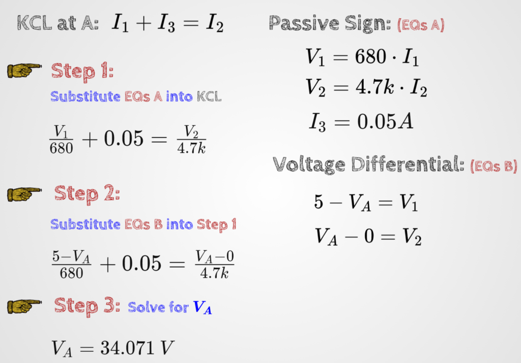
Alright, with all these equations we can find the voltage VA.
As you get more comfortable with circuit analysis, all the steps that we did so far can be done in one go. For now, we keep it like this so the reader can follow the steps easily.
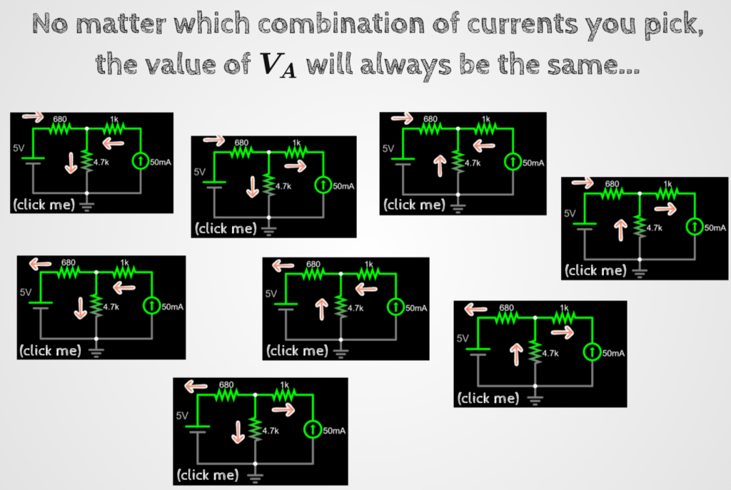
No matter which current or sign directions you pick, you will always get the same voltage for VA. Give it a try and pick random current directions and see if you can get the same VA voltage.
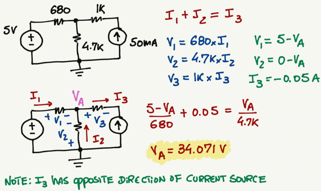
Different current directions example:
Different current directions example:
Animation with all possible current directions, keeping the sign convention positive all the time.
Now that we found VA and it is the same value independently of the current direction that you selected, we can adjust the current directions according to the convention of your interest (either conventional or electron flow).
Summary