ATMEGA32U4 Dev Board
ATMEGA32U4 Development Board
Introduction
The ATMEGA32U4 is the microprocessor used on the Arduino Leonardo boards. The board has 20 GPIO pins available.
The goal with this project is to build a development board with the ATMEGA32U4 chipset that can be integrated with a breadboard and enable the access to 2 additional GIPO pins (a total of 22 GPIO pins).
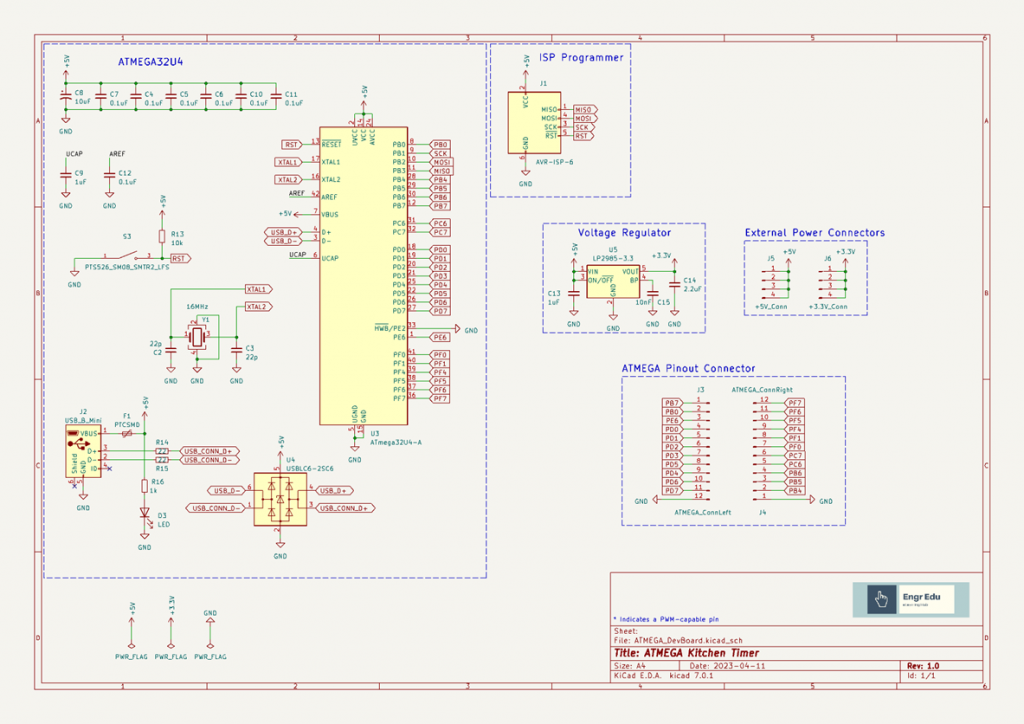
Design Stage
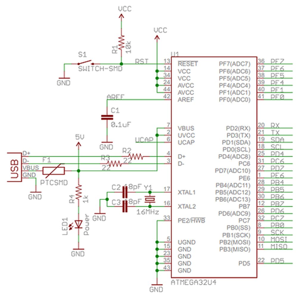
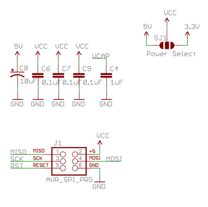
Besides having access to the 22 GPIO pins, we need to include the ISP programmer connector, a crystal, and a USB connector. The fuse and ESD protection are good practice to have in your designs but you can remove these modules if you want to design a more compact or cheap version of this board.
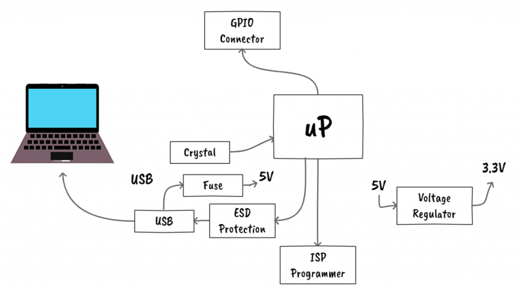
We can find some schematics online to support the new design. For example, Sparkfun developed an ATMEGA32U4 Breakout in the past. We can use this design as a starting point and incorporate additional features.
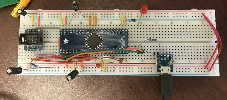
Prototype Stage
This stage might not be possible to do for some projects, but if possible, it is always good to test the components first before building the PCB.
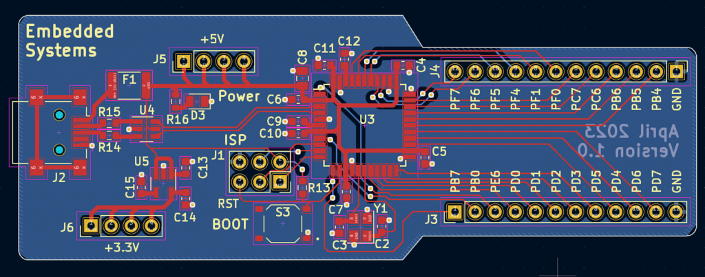
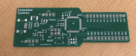
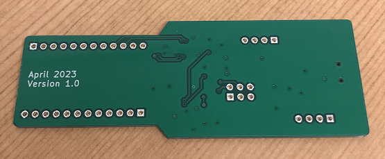
PCB Design
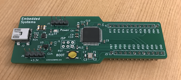
Assemble Stage
Flash USB Bootloader
The ATMEGA32U4 chip doesn't come with the USB bootloader flashed in it. We need to flash it using the AVRDUDE software and an AVR programmer.
AVR Programmer
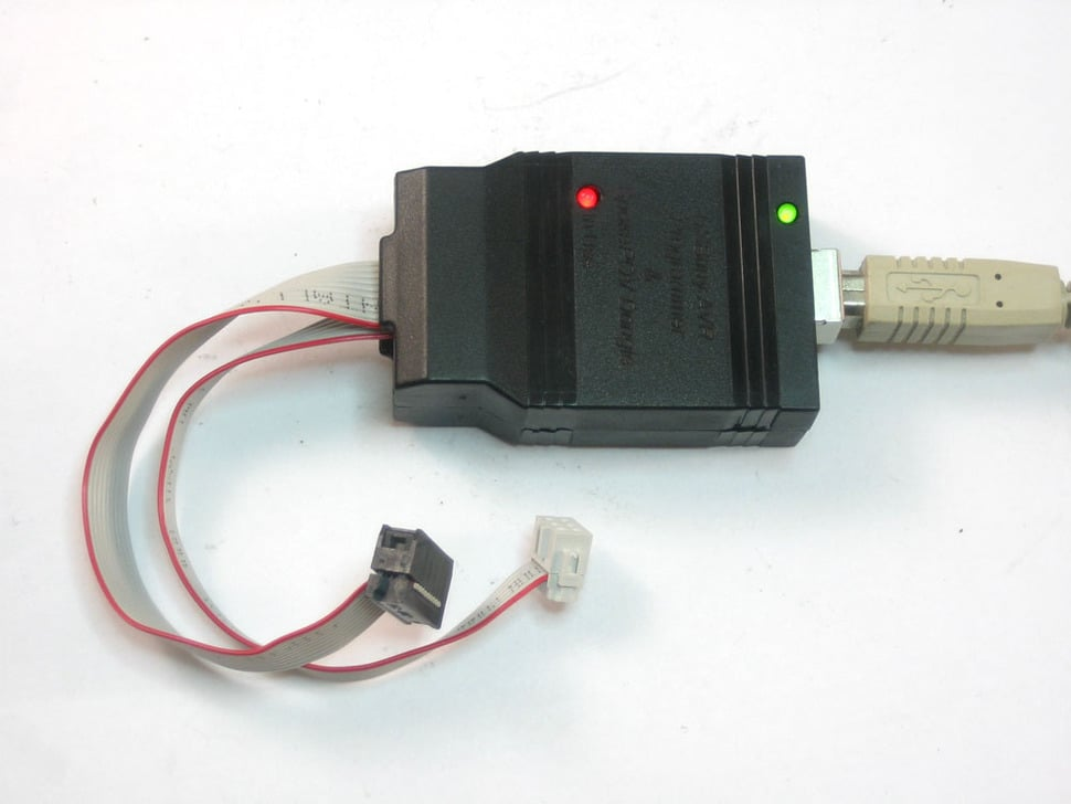
I am using the USBtinyISP AVR Programmer Kit (Link) by Adafruit.
I installed the AVR Programmer driver (Link) and the AVRDUDE software (Link).
AVRDUDE
AVRDUDE is a very popular command-line programmer for programming AVR chips. I follow this article to get familiar with the commands.
Flash the USB Bootloader
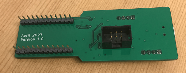
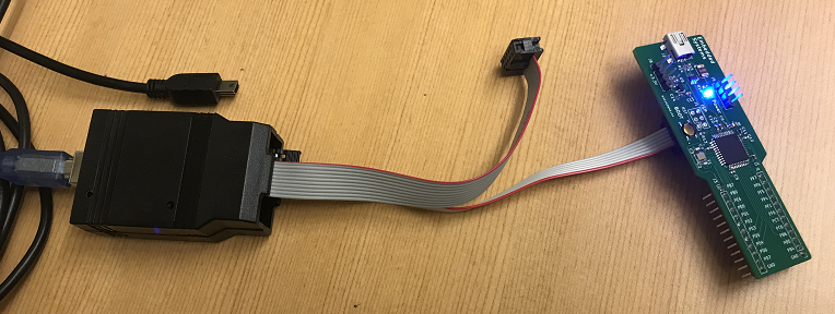
- Connect the 6 pin cable from the USBtinyISP AVR Programmer to your board first.
- Then connect the USB type B cable to your computer (following this order is important)
- Don't connect the USB from your PCB board to the computer (follow the image below).
- Download the USB Bootloader hex image (BootloaderCDC.hex) (Link)
- Open a command window (terminal) and go to the folder where you saved the hex image.
- Make sure that the "avrdude" software is accessible in your terminal.
- Run the command below to check if the AVR Programmer is talking with the ATMEGA chip.
avrdude -c usbtiny -p m32u4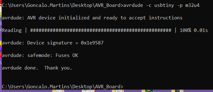
- In case all good, upload the Bootloader using the command below
avrdude -c usbtiny -p m32u4 -U flash:w:BootloaderCDC.hex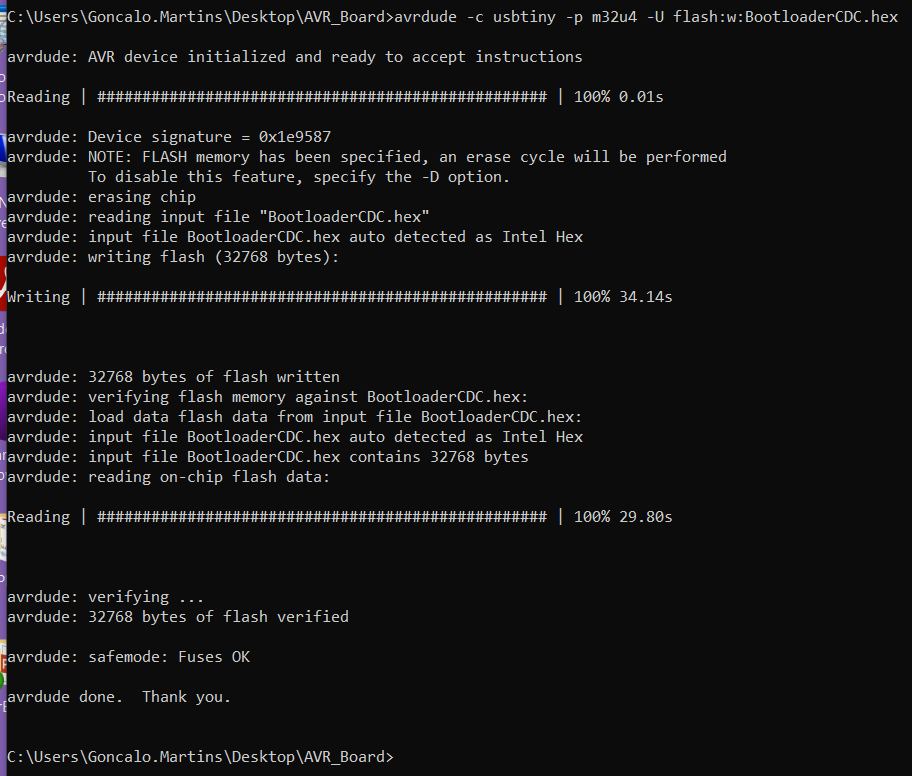
- We are good to disconnect the AVR Programmer and connect the USB cable from your PCB board.
Testing Stage
After flashing the USB bootloader, open your Arduino IDE and set the board to "Arduino Leonardo" and the programmer to "Arduino ISP".

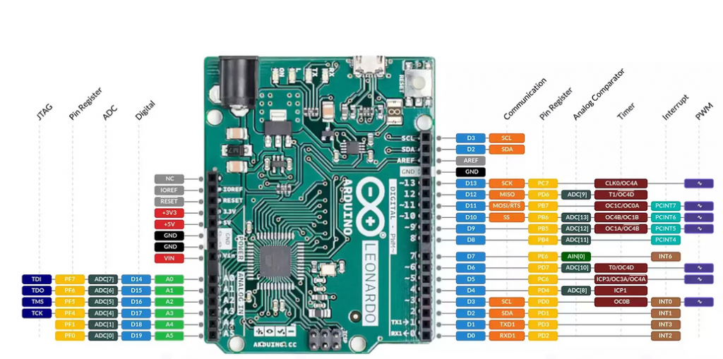
The figure below has the pinout for an Arduino Leonardo board. We can use it as a pinout guidance to map all the 22 GPIO pins accordingly.
Blink LED Arduino code
#include <Arduino.h>
#include <avr/power.h>

#define PF0   A5
#define PF1   A4
#define PF4   A3
#define PF5   A2
#define PF6   A1
#define PF7   A0

#define PC7   13
#define PC6   5   // LED
#define PB6   10
#define PB5   9
#define PB4   8
#define PD7   6
#define PD6   12
#define PD4   4   // LED

#define PD5   NotMappedPort_PD5   // Not Mapped on Leonardo Board
#define PD3   1   // TX
#define PD2   0   // RX
#define PD1   2
#define PD0   3
#define PB7   11

#define PB3   NotMappedPort_PB3   // MISO -> Not Mapped on Leonardo Board
#define PB2   NotMappedPort_PB2   // MOSI -> Not Mapped on Leonardo Board
#define PB1   NotMappedPort_PB1   // SCK -> Not Mapped on Leonardo Board
#define PB0   NotMappedPort_PB0   // SS -> Not Mapped on Leonardo Board
#define PE6   7

#define SLEEP_TIME  500

void setup() {
  if(F_CPU == 16000000) clock_prescale_set(clock_div_1);

  pinMode(PD4, OUTPUT);
  pinMode(PC6, OUTPUT);
}

void loop() {
  // put your main code here, to run repeatedly:
  digitalWrite(PD4, HIGH);
  digitalWrite(PC6, LOW);
  delay(SLEEP_TIME);
  digitalWrite(PD4, LOW);
  digitalWrite(PC6, HIGH);
  delay(SLEEP_TIME);
}

Additional Code
As you probably notice from the Blink LED code, some of the pins are not mapped on the Arduino IDE for the Arduino Leonardo board.
For these pins we need to access them by affecting the respective register.
As an example, if we want to set the pin PD5 as an output, we need to affect the following register:
DDRD = DDRD | B00100000; // PD5 as OutputTo set PD5 high and low we would do the following code:
PORTD = PORTD & B11011111;  // PD5 - LOW
PORTD = PORTD | B00100000;  // PD5 - HIGH
Writing to the registers in your code can become confusing to follow and understand what is going on. That is one of the strengths of using the Arduino IDE, it abstracts this register access by using the common pinMode and digitalWrite functions.
We can write our own functions my_pinMode and my_digitalWrite and make our code easier follow and understand. The code below doesn't show those functions but you have access to them under the ATMEGA32u4_Pin_Mapping.h and .cpp files (Link).
Arduino Code
#include <Arduino.h>
#include <avr/power.h>

#include "ATMEGA32u4_Pin_Mapping.h"

#define PF0   A5
#define PF1   A4
#define PF4   A3
#define PF5   A2
#define PF6   A1
#define PF7   A0

#define PC7   13
#define PC6   5
#define PB6   10
#define PB5   9
#define PB4   8
#define PD7   6
#define PD6   12
#define PD4   4

#define PD5   NotMappedPort_PD5   // Not Mapped on Leonardo Board
#define PD3   1   // TX
#define PD2   0   // RX
#define PD1   2
#define PD0   3
#define PB7   11

#define PB3   NotMappedPort_PB3   // MISO -> Not Mapped on Leonardo Board
#define PB2   NotMappedPort_PB2   // MOSI -> Not Mapped on Leonardo Board
#define PB1   NotMappedPort_PB1   // SCK -> Not Mapped on Leonardo Board
#define PB0   NotMappedPort_PB0   // SS -> Not Mapped on Leonardo Board
#define PE6   7

#define SLEEP_TIME  200

void setup() {
  // put your setup code here, to run once:
  pinMode(PD4, OUTPUT);
  pinMode(PD7, OUTPUT);

  pinMode(PD2, OUTPUT);

  /* Non Leonardo Pin */
  //DDRD = DDRD | B00100000;  // PD5 as Output
  my_pinMode(PD5, OUTPUT);
  //DDRB = DDRB | B00001111;  // PB3 to PB0 as Output
  my_pinMode(PB0, OUTPUT);
  my_pinMode(PB1, OUTPUT);
  my_pinMode(PB2, OUTPUT);
  my_pinMode(PB3, OUTPUT);

  if(F_CPU == 16000000) clock_prescale_set(clock_div_1);

  //Serial.begin(115200);
}

void loop() {
  // put your main code here, to run repeatedly:
  digitalWrite(PD4, HIGH);
  digitalWrite(PD7, LOW);
  /* Testing Code */
  digitalWrite(PD2, LOW);
  //PORTD = PORTD & B11011111;  // PD5 - LOW
  my_digitalWrite(PD5, LOW);
  //PORTB = PORTB & B11110000;  // PB3 to PB0 - LOW
  my_digitalWrite(PB0, LOW);
  my_digitalWrite(PB1, LOW);
  my_digitalWrite(PB2, LOW);
  my_digitalWrite(PB3, LOW);
  /* ------------ */
  delay(SLEEP_TIME);
  digitalWrite(PD4, LOW);
  digitalWrite(PD7, HIGH);
  /* Testing Code */
  digitalWrite(PD2, HIGH);
  //PORTD = PORTD | B00100000;  // PD5 - HIGH
  my_digitalWrite(PD5, HIGH);
  //PORTB = PORTB | B00001111;  // PB3 to PB0 - HIGH
  my_digitalWrite(PB0, HIGH);
  my_digitalWrite(PB1, HIGH);
  my_digitalWrite(PB2, HIGH);
  my_digitalWrite(PB3, HIGH);
  /* ------------ */
  delay(SLEEP_TIME);

  //Serial.println("Working");
}
GitHub Repository
Code (Arduino Leonardo Compatible)
Bootloader
Gerber Files
References
- [Ref 1] "Installing Arduino Bootloader on an ATmega32U4", electronut Website [Article]
- [Ref 2] "Using the programmer with AVRDUDE", Adafruit Website [Article]
Sponsor