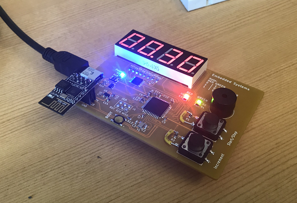
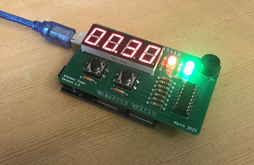
Kitchen Timer (IoT)
Kitchen Timer (IoT)
Introduction
This project is the project used during the Embedded System Design class to show one way of addressing the design, building and testing of an embedded system, from proof of concept, to fist prototype and final iteration boards.
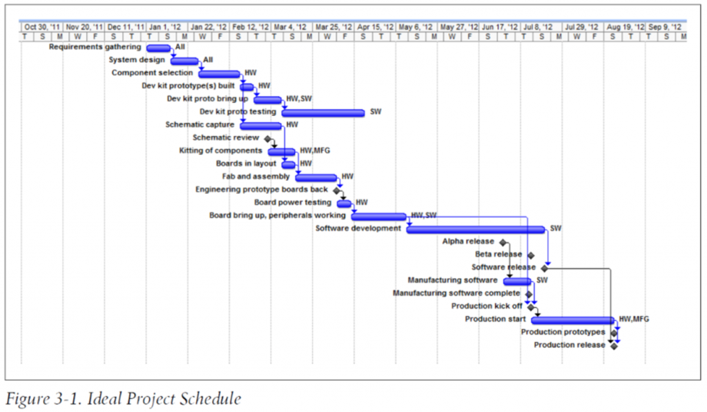
As a project timeline guideline, we will be following the schedule below [Gantt Chart from “Making Embedded Systems” reference book].
The project is divide into 3 Phases:
- Phase A: Proof of Concept,
- Phase B: Prototype
- Phase C: Final Iteration
Phase A: Proof of Concept
Project Requirements
This stage is normally done in conjunction with a sponsor/company interested in the product. Since there is no company associated with this project, the requirements are going to be a bit relaxed and students can actually add more features if they want to.
Hardware requirements:
- x1 buzzer
- x2 user buttons
- x2 status LEDs
- x1 7-Segment display
Software requirements:
- Turn on/off the timer
- Increment the timer
Additional feature:
- If possible, include some IoT capability. For example, the ability to interact with the timer over internet, phone or computer
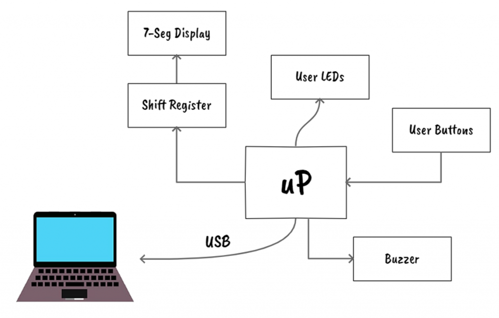
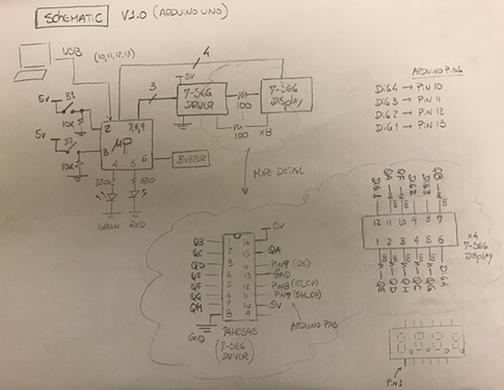
System Design
It is always good to start with a draft of a system block diagram. In this stage, some of the project requirements get polished and it is a good time to make some design decisions too. I will give some design example decision below.
If possible, you can polish and clean up your block diagram so it can be included on a report later.
Buttons
Normally buttons have jitter and some sort of debounce mechanics should be included in your design. These debounce mechanisms can be done in software or hardware [REF 1][REF 5]. The decision here depends on some factors but for this design we will be debouncing the buttons in software to save some hardware components and PCB space.
7-Seg Display
The way to interface with the user is an important step during the design stage. The decision on what type of screen or display is also correlated with the complexity of the code required to render the information to the user.
For simplicity, we are going to use a 7-seg display and we are also going to use a shift register to interface between the microprocessor and the display in order to reduce the number of pins required to operate the 7-seg display.
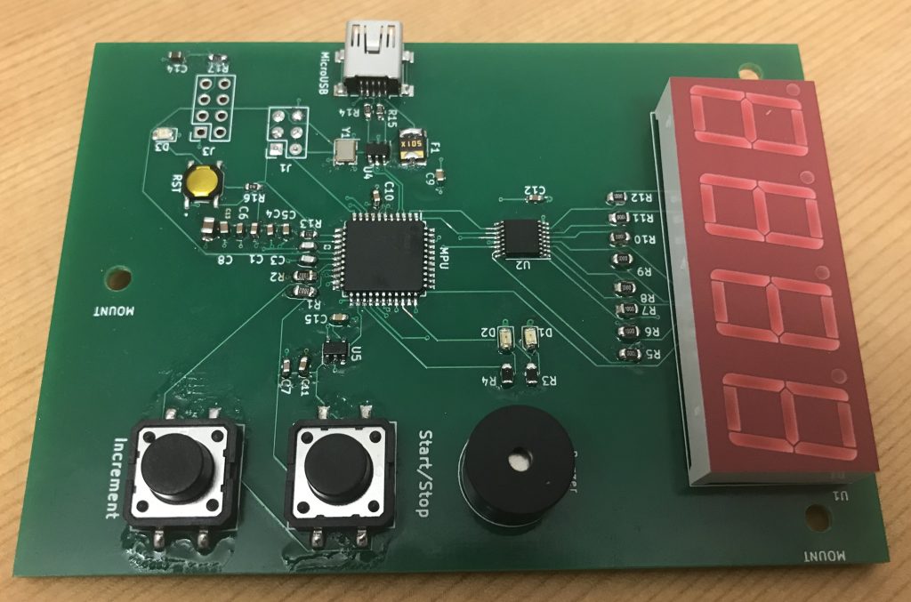
Components Selection
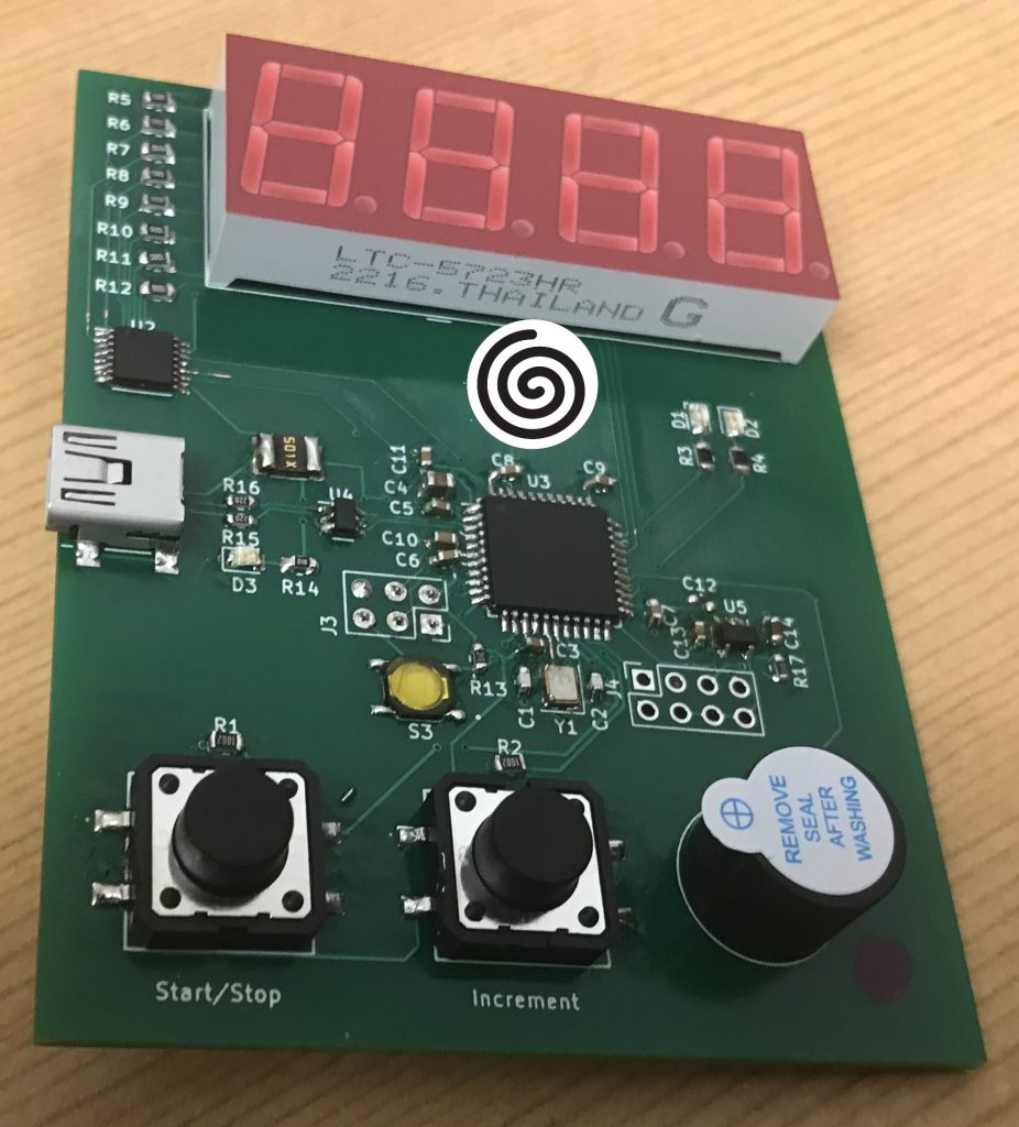
For this stage, the goal is to develop a quick prototype where it is possible to test the software and hardware solutions from the precious sections. For that, we will be developing an Arduino shield that can be used with an Arduino Uno.
There is a chance that the Arduino Uno might not be the microprocessor used in the next phases but it is sufficient for a quick rapid prototype and show the components interacting with some initial code.
Components:
- x1 Arduino Uno
- x1 7-Seg Display
- x1 Shift Register 8-Bit (SN74HC595)
- x2 Buttons
- x2 LEDs
- Resistors and Capacitors
- x1 Buzzer
Build Prototype
This stage might not be possible to do for some projects, but if possible, it is always good to test the components first before building the PCB.
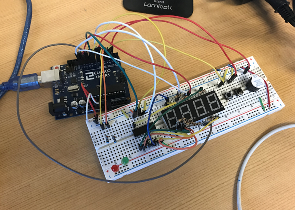
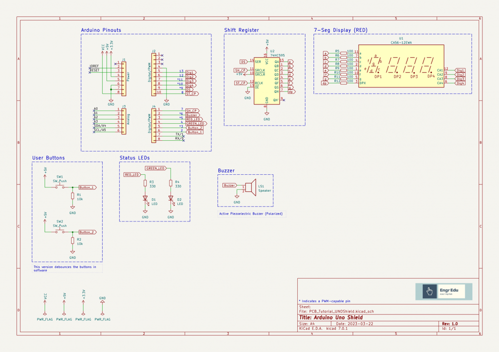
However, it is a good time to design a preliminary schematic of your system with the desired pinouts connections.
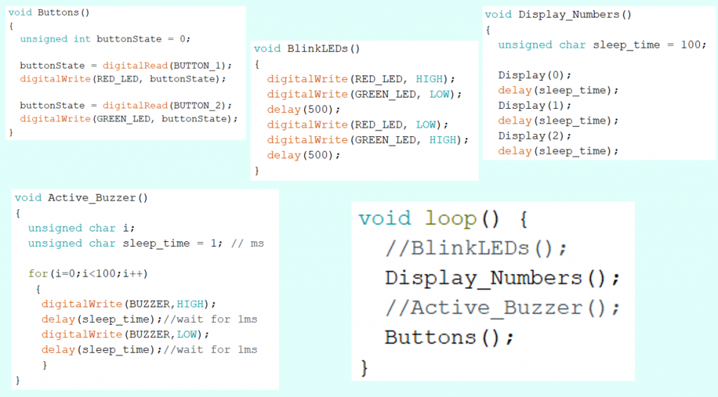
Initial Code Development
The software team can also start developing some code to interface the components. This is the opportunity:
- to understand the real-time constraints of the application.
- to see if it is required additional hardware to interface the components to alleviate the code.
- to see how many inputs/outputs, and microprocessor resources (e.g.: SPI, I2C, UART, ADC, DAC, etc) will be required.
Since this is a proof of concept, it is ok if the selected microprocessor can't do all the required code at once. But it should at least be able to interface properly with all desired components of the system, even if you need to test them individually.
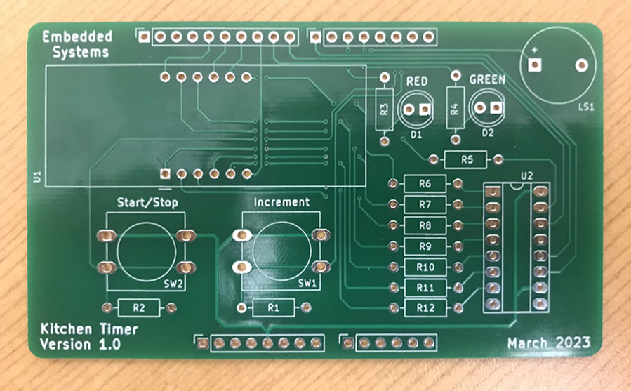
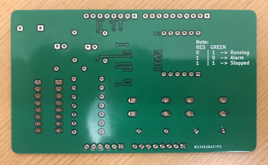
PCB Design
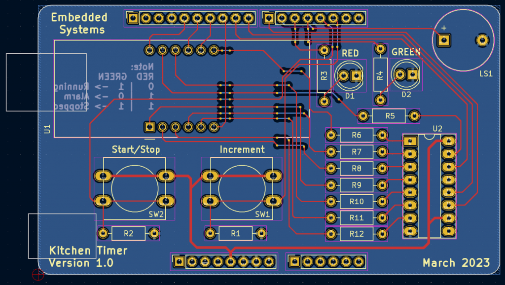
Assemble Stage
Software Development
With the shield fabricated it is now time to try to develop the code of this proof of concept board to it's maximum potential.
The code presented in the "Initial Code Development" section had some real-time limitations. The functions to interact with the buttons, leds, and 7-seg display were running in a pooling fashion way.
The pooling method is not the best approach for this particular case because we are facing a concurrency problem. There are different ways to address this challenge. The slides below go over different approaches to mitigate this issue.
Different Types of Program Flows
Below you can find two solutions: solution 1 using interrupt routines, and solution 2 using FreeRTOS.
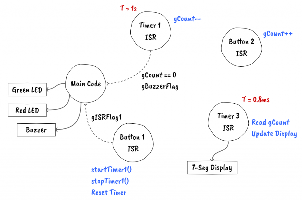
Solution 1: Final Kitchen Timer Code (with interrupts)
Code block diagrams can help visualizing how the code is interacting with peripherals, communication between interrupt routines, and main loop.
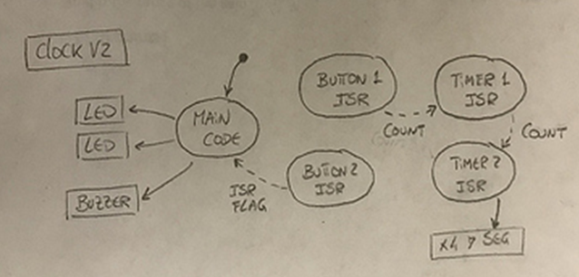
As you get closer to the final version of the code, clean up those block diagrams. The amount of information that you include in the block diagrams is up to you. You can also have multiple block diagrams depicting different system interactions.
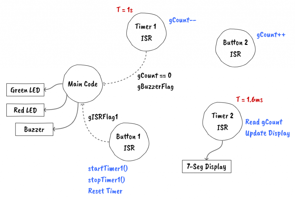
Quick note, the code below is still missing a debounce code for the buttons.
#define BUTTON_2  2  // Inc Timer
#define BUTTON_1  3  // Start/Stop Timer and Stop Buzzer
#define GREEN_LED 4
#define RED_LED   5
#define BUZZER    6

#define DATA      9 // DS
#define LATCH     8 // ST_CP
#define CLOCK     7 // SH_CP

#define DIGIT_4   10
#define DIGIT_3   11
#define DIGIT_2   12
#define DIGIT_1   13

// 7-Seg Display Variables
unsigned char gtable[]=
{0x3f,0x06,0x5b,0x4f,0x66,0x6d,0x7d,0x07,0x7f,0x6f,0x77,0x7c
,0x39,0x5e,0x79,0x71,0x00};
byte gCurrentDigit;

// Volatile Variables
volatile unsigned char gISRFlag1   = 0;
volatile unsigned char gBuzzerFlag = 0;

// Timer Variables
#define DEFAULT_COUNT 30     // default value is 30secs
volatile int  gCount        = DEFAULT_COUNT;
unsigned char gTimerRunning = 0;

unsigned int gReloadTimer1 = 62500; // corresponds to 1 second
byte         gReloadTimer2 = 10;  // display refresh time

/**
 * @brief Setup peripherals and timers
 * @param
 * @return
 */
void setup() {
  // LEDs Pins
  pinMode(RED_LED, OUTPUT);
  pinMode(GREEN_LED, OUTPUT);

  // LEDs -> Timer Stopped
  digitalWrite(RED_LED, HIGH);
  digitalWrite(GREEN_LED, HIGH);

  // Button Pins
  pinMode(BUTTON_1, INPUT_PULLUP);
  attachInterrupt(digitalPinToInterrupt(BUTTON_1), buttonISR1, RISING);
  pinMode(BUTTON_2, INPUT_PULLUP);
  attachInterrupt(digitalPinToInterrupt(BUTTON_2), buttonISR2, RISING);

  // Buzer Pins
  pinMode(BUZZER, OUTPUT);

  // Buzzer -> Off
  digitalWrite(BUZZER,LOW);

  // 7-Seg Display
  pinMode(DIGIT_1, OUTPUT);
  pinMode(DIGIT_2, OUTPUT);
  pinMode(DIGIT_3, OUTPUT);
  pinMode(DIGIT_4, OUTPUT);

  // Shift Register Pins
  pinMode(LATCH, OUTPUT);
  pinMode(CLOCK, OUTPUT);
  pinMode(DATA, OUTPUT);

  dispOff();  // turn off the display

  // Initialize Timer1 (16bit) -> Used for clock
  // Speed of Timer1 = 16MHz/256 = 62.5 KHz
  noInterrupts();
  TCCR1A = 0;
  TCCR1B = 0;
  OCR1A = gReloadTimer1; // compare match register 16MHz/256
  TCCR1B |= (1<<WGM12);   // CTC mode
  // Start Timer by setting the prescaler -> done using the start button
  //TCCR1B |= (1<<CS12);    // 256 prescaler
  TIMSK1 |= (1<<OCIE1A);  // enable timer compare interrupt
  interrupts();

  // Initialize Timer2 (8bit) -> Used to refresh display
  // Speed of Timer2 = 16MHz/1024 = 15.625 KHz
  TCCR2A = 0;
  TCCR2B = 0;
  OCR2A = gReloadTimer2;                     // max value 2^8 - 1 = 255
  TCCR2A |= (1<<WGM21);
  TCCR2B = (1<<CS22) | (1<<CS21) | (1<<CS20); // 1204 prescaler
  TIMSK2 |= (1<<OCIE2A);
  interrupts();                               // enable all interrupts
}

/**
 * @brief Shifts the bits through the shift register
 * @param num
 * @param dp
 * @return
 */
void display(unsigned char num, unsigned char dp)
{
  digitalWrite(LATCH, LOW);
  shiftOut(DATA, CLOCK, MSBFIRST, gtable[num] | (dp<<7));
  digitalWrite(LATCH, HIGH);
}

/**
 * @brief Turns the 7-seg display off
 * @param
 * @return
 */
void dispOff()
{
   digitalWrite(DIGIT_1, HIGH);
   digitalWrite(DIGIT_2, HIGH);
   digitalWrite(DIGIT_3, HIGH);
   digitalWrite(DIGIT_4, HIGH);
}

/**
 * @brief Button 2 ISR
 * @param
 * @return
 */
void buttonISR2()
{
  // Increment Clock
  gCount++;
}

/**
 * @brief Button 1 ISR
 * @param
 * @return
 */
void buttonISR1()
{
  // Set ISR Flag
  gISRFlag1 = 1;
}

/**
 * @brief Timer 2 ISR
 * @param TIMER2_COMPA_vect
 * @return
 */
ISR(TIMER2_COMPA_vect)   // Timer2 interrupt service routine (ISR)
{
  dispOff();  // turn off the display

  switch (gCurrentDigit)
  {
    case 1: //0x:xx
      display( int((gCount/60) / 10) % 6, 0 );   // prepare to display digit 1 (most left)
      digitalWrite(DIGIT_1, LOW);  // turn on digit 1
      break;

    case 2: //x0:xx
      display( int(gCount / 60) % 10, 1 );   // prepare to display digit 2
      digitalWrite(DIGIT_2, LOW);     // turn on digit 2
      break;

    case 3: //xx:0x
      display( (gCount / 10) % 6, 0 );   // prepare to display digit 3
      digitalWrite(DIGIT_3, LOW);    // turn on digit 3
      break;

    case 4: //xx:x0
      display(gCount % 10, 0); // prepare to display digit 4 (most right)
      digitalWrite(DIGIT_4, LOW);  // turn on digit 4
      break;

    default:
      break;
  }

  gCurrentDigit = (gCurrentDigit % 4) + 1;
}

/**
 * @brief Timer 1 ISR
 * @param TIMER1_COMPA_vect
 * @return
 */
ISR(TIMER1_COMPA_vect)  // Timer1 interrupt service routine (ISR)
{
  gCount--;

  if(gCount == 0)
  {
      // Stop Timer
      stopTimer1();

      // Raise Alarm
      gBuzzerFlag = 1;
      gTimerRunning = 0;
  }
}

/**
 * @brief Stop Timer 1
 * @param
 * @return
 */
void stopTimer1()
{
  // Stop Timer
  TCCR1B &= 0b11111000; // stop clock
  TIMSK1 = 0; // cancel clock timer interrupt
}

/**
 * @brief Start Timer 1
 * @param
 * @return
 */
void startTimer1()
{
  // Start Timer
  TCCR1B |= (1<<CS12);    // 256 prescaler
  TIMSK1 |= (1<<OCIE1A);  // enable timer compare interrupt
}

/**
 * @brief Turn On Buzzer
 * @param
 * @return
 */
void activeBuzzer()
{
  unsigned char i;
  unsigned char sleepTime = 1; // ms

  for(i=0;i<100;i++)
  {
    digitalWrite(BUZZER,HIGH);
    delay(sleepTime);//wait for 1ms
    digitalWrite(BUZZER,LOW);
    delay(sleepTime);//wait for 1ms
  }
}

/**
 * @brief Main Loop
 * @param
 * @return
 */
void loop()
{
  // Attend Button 2 ISR
  if(gISRFlag1 == 1)
  {
    // Reset ISR Flag
    gISRFlag1 = 0;

    if(gTimerRunning == 0)
    {
      // Start Timer
      gTimerRunning = 1;

      if(gCount == 0)
        gCount = DEFAULT_COUNT;

      if(gBuzzerFlag == 1)
      {
        gBuzzerFlag = 0;

        // LEDs -> Timer Stopped
        digitalWrite(RED_LED, HIGH);
        digitalWrite(GREEN_LED, HIGH);
      }
      else
      {
        startTimer1();
        // LEDs -> Timer Running
        digitalWrite(RED_LED, LOW);
        digitalWrite(GREEN_LED, HIGH);
      }
    }
    else
    {
      // Stop Timer
      stopTimer1();
      gTimerRunning = 0;

      // LEDs -> Timer Running
      digitalWrite(RED_LED, HIGH);
      digitalWrite(GREEN_LED, HIGH);
    }
  }

  // Attend gBuzzerFlag
  if(gBuzzerFlag == 1)
  {
    // Make Noise...
    digitalWrite(RED_LED, HIGH);
    digitalWrite(GREEN_LED, LOW);
    activeBuzzer();
  }
}
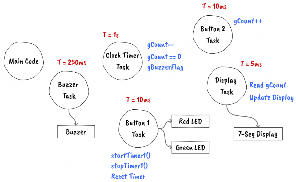
Solution 2: Final Kitchen Timer Code (with FreeRTOS)
Luckily in this case, the code is not much different than solution 1. The code that was previously running inside the interrupt routines is now done inside tasks that are managed by the FreeRTOS scheduler.
Quick note, the version of the code below, includes a simple debounce mechanism for the buttons.
// Include Arduino FreeRTOS library
#include <Arduino_FreeRTOS.h>

#define BUTTON_2  2  // Inc Timer
#define BUTTON_1  3  // Start/Stop Timer and Stop Buzzer
#define GREEN_LED 4
#define RED_LED   5
#define BUZZER    6

#define DATA      9 // DS
#define LATCH     8 // ST_CP
#define CLOCK     7 // SH_CP

#define DIGIT_4   10
#define DIGIT_3   11
#define DIGIT_2   12
#define DIGIT_1   13

// 7-Seg Display Variables
unsigned char gTable[]=
{0x3f,0x06,0x5b,0x4f,0x66,0x6d,0x7d,0x07,0x7f,0x6f,0x77,0x7c
,0x39,0x5e,0x79,0x71,0x00};

// Timer Variables
#define DEFAULT_COUNT 30     // default value is 30secs
int  gCount = DEFAULT_COUNT;

char gBuzzerFlag = 0;
unsigned char gTimerRunning = 0;

//define task handles
TaskHandle_t TaskClockTimer_Handler;

void setup() {

  /**
   * Set up Pins
   */
   // LEDs Pins
   pinMode(RED_LED, OUTPUT);
   pinMode(GREEN_LED, OUTPUT);

   // LEDs -> Timer Stopped
   digitalWrite(RED_LED, HIGH);
   digitalWrite(GREEN_LED, HIGH);

   // Button Pins
   pinMode(BUTTON_1, INPUT);
   pinMode(BUTTON_2, INPUT);

   // Buzer Pins
   pinMode(BUZZER, OUTPUT);

   // Buzzer -> Off
   digitalWrite(BUZZER,LOW);

   // 7-Seg Display
   pinMode(DIGIT_1, OUTPUT);
   pinMode(DIGIT_2, OUTPUT);
   pinMode(DIGIT_3, OUTPUT);
   pinMode(DIGIT_4, OUTPUT);

   // Shift Register Pins
   pinMode(LATCH, OUTPUT);
   pinMode(CLOCK, OUTPUT);
   pinMode(DATA, OUTPUT);

  dispOff();  // turn off the display

  // 7-Seg Display Task -> Running time 5 ms
  xTaskCreate(TaskDisplay, // Task function
              "Display", // A name just for humans
              128,  // This stack size can be checked & adjusted by reading the Stack Highwater
              NULL,
              0, // Priority, with 3 (configMAX_PRIORITIES - 1) being the highest, and 0 being the lowest.
              NULL);

  // Clock timer Task -> Running time 1 second
  xTaskCreate(TaskClockTimer, // Task function
              "ClockTimer", // Task name
              128,  // Stack size
              NULL,
              0, // Priority
              &TaskClockTimer_Handler);

  stopTaskClockTimer();

  // Buzzer Task -> Running at 250 ms
  xTaskCreate(TaskBuzzer, // Task function
              "Buzzer", // Task name
              128, // Stack size
              NULL,
              0, // Priority
              NULL );

  // Read Button 2 Task -> Running at 10 ms
  xTaskCreate(TaskReadButton2, // Task function
              "ReadButton2", // Task name
              128,  // Stack size
              NULL,
              0, // Priority
              NULL);

  // Read Button 1 Task -> Running at 10 ms
  xTaskCreate(TaskReadButton1, // Task function
              "ReadButton1", // Task name
              128,  // Stack size
              NULL,
              0, // Priority
              NULL);
}

void loop() {}

// ------
// TASKS
// ------

/**
 * 7-Seg Display Task
 * Refresh display -> Running at 5 ms
 */
void TaskDisplay(void * pvParameters) {
  (void) pvParameters;

  byte current_digit;

  for (;;)
  {
    dispOff();  // turn off the display

    switch (current_digit)
    {
      case 1: //0x:xx
        display( int((gCount/60) / 10) % 6, 0 );   // prepare to display digit 1 (most left)
        digitalWrite(DIGIT_1, LOW);  // turn on digit 1
        break;

      case 2: //x0:xx
        display( int(gCount / 60) % 10, 1 );   // prepare to display digit 2
        digitalWrite(DIGIT_2, LOW);     // turn on digit 2
        break;

      case 3: //xx:0x
        display( (gCount / 10) % 6, 0 );   // prepare to display digit 3
        digitalWrite(DIGIT_3, LOW);    // turn on digit 3
        break;

      case 4: //xx:x0
        display(gCount % 10, 0); // prepare to display digit 4 (most right)
        digitalWrite(DIGIT_4, LOW);  // turn on digit 4
    }

    current_digit = (current_digit % 4) + 1;

    // 5 ms
    vTaskDelay( 5 / portTICK_PERIOD_MS );
  }
}

/**
 * Clock Timer Task
 * If timer is on, decrements timer by one second.
 */
void TaskClockTimer(void *pvParameters)
{
  (void) pvParameters;

  for (;;)
  {
    gCount--;

    if(gCount == 0)
    {
      //raise alarm
      gBuzzerFlag = 1;
      gTimerRunning = 0;

      //stop timer
      stopTaskClockTimer();
    }

    // 1 second
    vTaskDelay( 1000 / portTICK_PERIOD_MS );
  }
}

/*
 * Buzzer Task
 */
void TaskBuzzer(void *pvParameters)
{
  (void) pvParameters;

  unsigned char state = 0;

  for (;;)
  {
    // Attend gBuzzerFlag
    if(gBuzzerFlag == 1)
    {
      // Make Noise...
      digitalWrite(RED_LED, HIGH);
      digitalWrite(GREEN_LED, LOW);

      digitalWrite(BUZZER, HIGH);
      vTaskDelay( 250 / portTICK_PERIOD_MS );
      digitalWrite(BUZZER, LOW);
      vTaskDelay( 250 / portTICK_PERIOD_MS );
    }
    else
      digitalWrite(BUZZER, LOW);

    // One tick delay (15ms) in between reads for stability
    vTaskDelay(1);
  }
}

/**
 * Read Button 2 Task
 * Reads button 2, Inc timer
 */
void TaskReadButton2(void *pvParameters)
{
  (void) pvParameters;
  unsigned int buttonState = 0;  // variable for reading the pushbutton status

  for (;;)
  {
    // Read Button 2 -> pooling method is fine in this case
    buttonState = digitalRead(BUTTON_2);

    // TODO -> implement the code to debounce the button
    if(buttonState == 1)
    {
      vTaskDelay( 250 / portTICK_PERIOD_MS );  // Very simple debounce

      gCount++;
    }

    // One tick delay (15ms) in between reads for stability
    vTaskDelay(1);
  }
}

/**
 * Read Button 1 Task
 * Reads button 1, Start/Stop timer
 */
void TaskReadButton1(void *pvParameters)
{
  (void) pvParameters;

  unsigned int buttonState = 0;  // variable for reading the pushbutton status

  for (;;)
  {
    // Read Button 1 -> pooling method is fine in this case
    buttonState = digitalRead(BUTTON_1);

    if(buttonState == 1)
    {
      vTaskDelay( 250 / portTICK_PERIOD_MS );  // Very simple debounce

      if(gTimerRunning == 0)
      {
        // Start Clock Timer
        gTimerRunning = 1;

        if(gCount == 0)
        {
          gCount = DEFAULT_COUNT;
        }

        if(gBuzzerFlag == 1)
        {
          gBuzzerFlag = 0;

          // LEDs -> Timer Stopped
          digitalWrite(RED_LED, HIGH);
          digitalWrite(GREEN_LED, HIGH);
        }
        else
        {
          startTaskClockTimer();
          // LEDs -> Timer Running
          digitalWrite(RED_LED, LOW);
          digitalWrite(GREEN_LED, HIGH);
        }
      }
      else
      {
        // Stop Timer
        stopTaskClockTimer();
        gTimerRunning = 0;

        // LEDs -> Timer Running
        digitalWrite(RED_LED, HIGH);
        digitalWrite(GREEN_LED, HIGH);
      }
    }

    // One tick delay (15ms) in between reads for stability
    vTaskDelay(1);
  }
}

// --------------------------------------------------

void stopTaskClockTimer()
{
  vTaskSuspend(TaskClockTimer_Handler);
}

void startTaskClockTimer()
{
  vTaskResume(TaskClockTimer_Handler);
}

void dispOff()
{
   digitalWrite(DIGIT_1, HIGH);
   digitalWrite(DIGIT_2, HIGH);
   digitalWrite(DIGIT_3, HIGH);
   digitalWrite(DIGIT_4, HIGH);
}

void display(unsigned char num, unsigned char dp)
{
  digitalWrite(LATCH, LOW);
  shiftOut(DATA, CLOCK, MSBFIRST, gTable[num] | (dp<<7));
  digitalWrite(LATCH, HIGH);
}
Phase B: Prototype
The goal with this phase is to move the proof of concept prototype to a prototype that shapes the board closer to the final idea of the product.
Project Requirements
In this stage, we eliminate components from the development board that are not needed (e.g.: Arduino Uno board), and add additional components that can potential enhance the product (e.g.: communication module added -> ESP8266).
Note: You should only add components/modules if from the software side there is room to add the code required to enable these features.
The project requirements should also settle at this stage, or at least they shouldn't change that much from this point on.
The only thing that I will be adding to this project is the ability to communicate externally with the clock.
Hardware Requirements:
- Substitute the Arduino Uno board with a microprocessor that has similar CPU specs but more available pinouts.
Communication Requirements:
- The ability to control the device remotely (IoT).
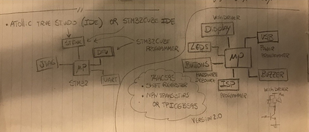
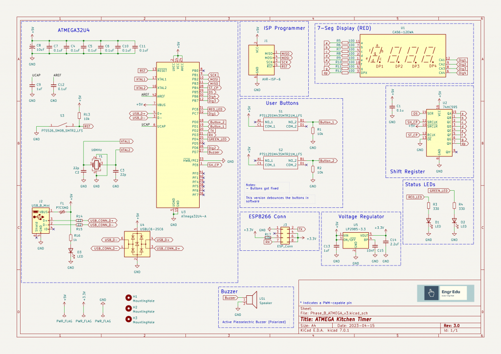
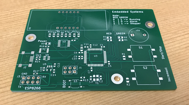
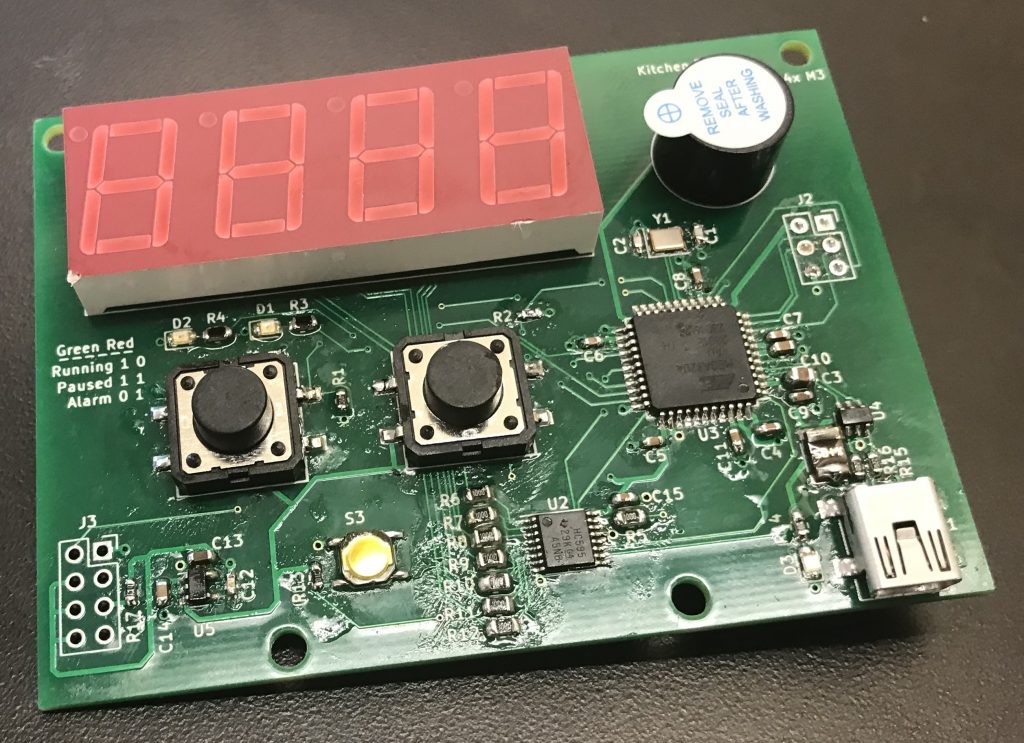
System Design
With the new requirements in place, we redesign the block diagram to include the new microprocessor, communication module and additional support modules.
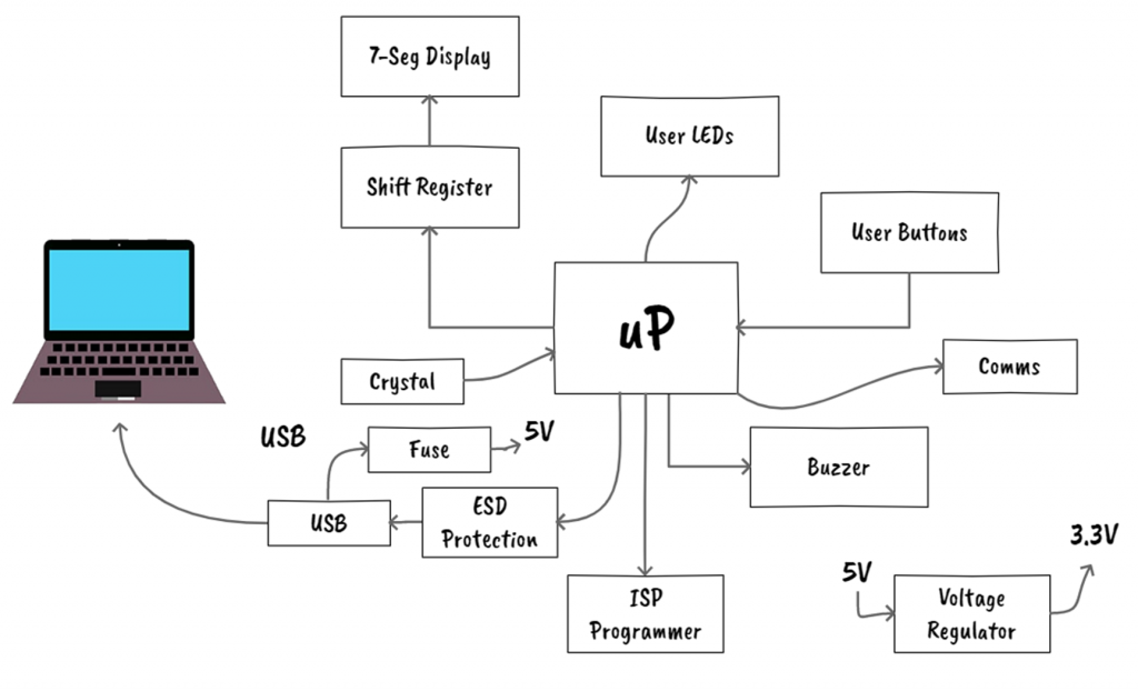
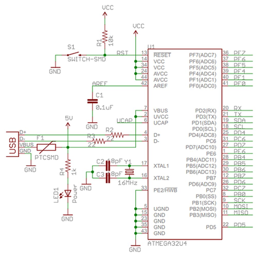
Microprocessor
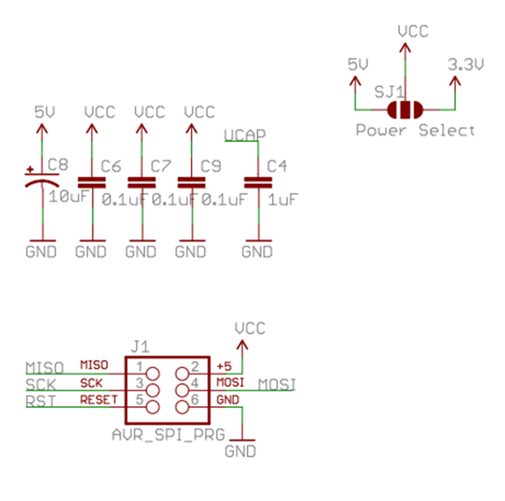
The microprocessor used in this stage is the ATMEGA32U4. It is the same microprocessor used in the Arduino Leonardo boards. The ISP Programmer, Crystal, and USB modules are added to support the uP module.
A comparison between the Leonardo and Uno board can be found here. The ATMEGA32U4 has additional pins which allows us to include the communication module without affecting the rest of the design.
Communications
For the communications modules, I will be using the ESP8266. I will be using this module in a format that it is easier to integrate (Link) with the PCB board. Since this module works at 3.3V, we need a voltage regulator to drop the voltage down to the required voltage.
Build Prototype
This stage might not be possible to do for some projects, but if possible, it is always good to test the components first before building the PCB.
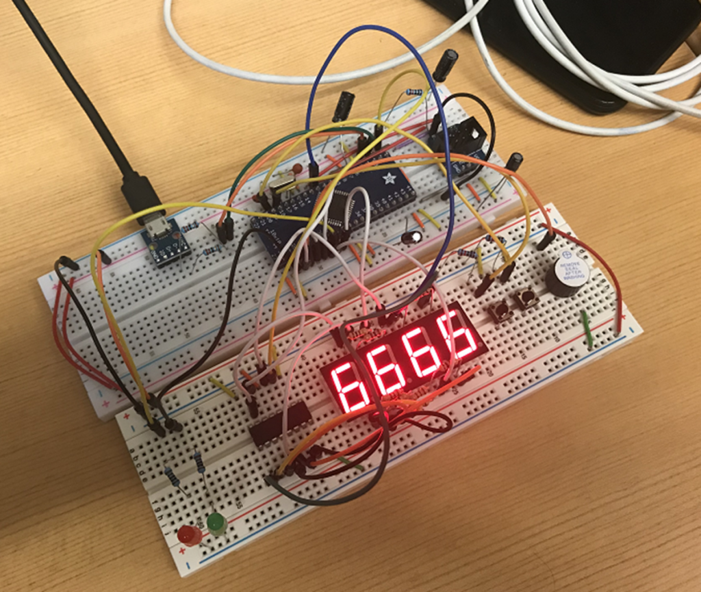
In this case, I was able to test out the ATMEGA32U4 that will be included on the PCB board. The rest of the modules are the same as the ones used during Phase A.
You can find the design of a development board for this microprocessor here.
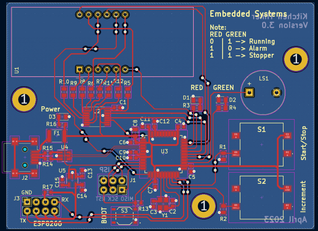
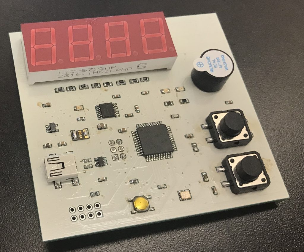
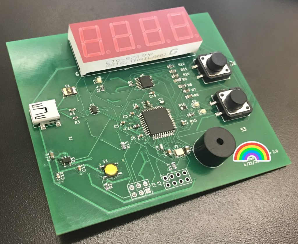
Assemble Stage
Version 2.0
This version had some design mistakes that were fixed in version 3.0.
Design Mistakes:
- The pull down resistors for the buttons were connected to the wrong pins.
- The ESP8266 module had the wrong pinout direction.
The boards were manufactured by PCBWay.
Note: the PCB's were manufactured properly. The mistakes were done at PCB layout stage before sending the boards to PCBWay.
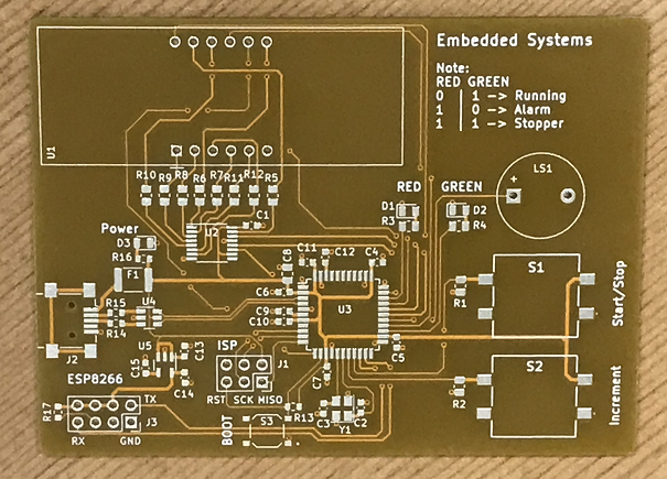
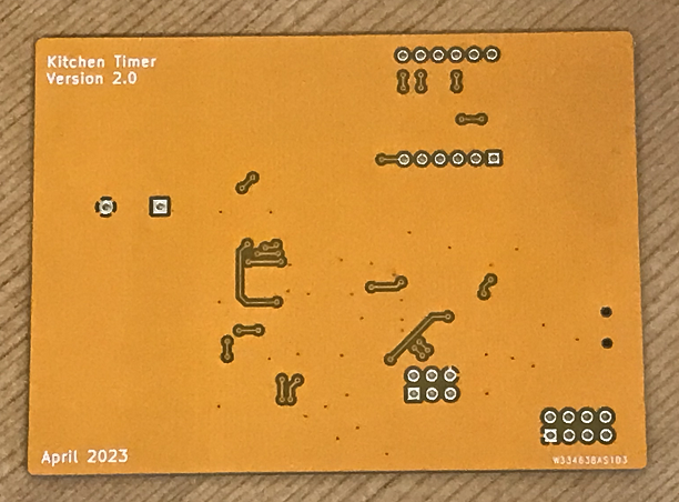
Assembled in house.
The boards were manufactured by PCBWay.
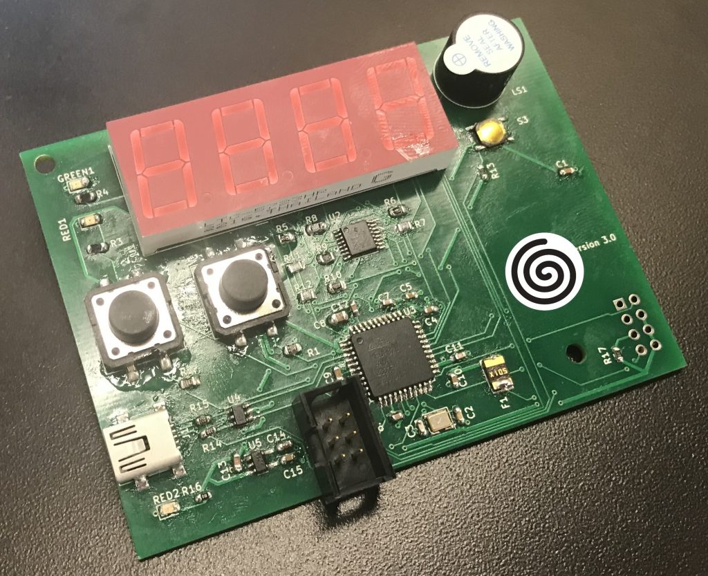
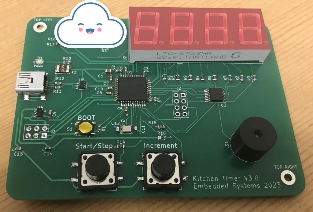
Version 3.0
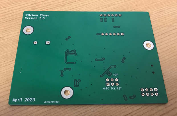
Assemble in progress...
Software Development
The first two solutions below have the same code from Phase A adapted to the new microprocessor (ATMEGA32U4). I did this as an intermediate step to make sure that the code is running properly before integrating the ESP8266 module with the system.
Solution 1: with interrupts (Phase A code adpatation)
Code block diagrams can help visualizing how the code is interacting with peripherals, communication between interrupt routines, and main loop.
The main difference from Phase A code is the use of timer 3 instead of timer 2. The Arduino Uno board (which has an ATmega328P) has Timer0, Timer1 and Timer2 (check page 49 of the datasheet). The ATMEGA32U4 chipset has Timer0, Timer1, Timer3 and Timer4 (check page 63 of the datasheet).
Quick note, the code below is still missing a debounce code for the buttons.
#include <Arduino.h>
#include <avr/power.h>

#define PF0   A5
#define PF1   A4
#define PF4   A3
#define PF5   A2
#define PF6   A1
#define PF7   A0

#define DIGIT_1   13  // PC7
#define RED_LED   5   // PC6
#define DIGIT_4   10  // PB6
#define DATA      9   // PB5 -> DS
#define LATCH     8   // PB4 -> ST_CP
#define BUZZER    6   // PD7
#define DIGIT_2   12  // PD6
#define GREEN_LED 4   // PD4

#define PD5       NotMappedPort_PD5 // Not Mapped on Leonardo Board
#define PD3       1                 // TX
#define PD2       0                 // RX
#define BUTTON_1  2                 // PD1 -> Start/Stop Timer and Stop Buzzer
#define BUTTON_2  3                 // PD0 -> Inc Timer
#define DIGIT_3   11                // PB7

#define PB3   NotMappedPort_PB3   // MISO -> Not Mapped on Leonardo Board
#define PB2   NotMappedPort_PB2   // MOSI -> Not Mapped on Leonardo Board
#define PB1   NotMappedPort_PB1   // SCK -> Not Mapped on Leonardo Board
#define PB0   NotMappedPort_PB0   // SS -> Not Mapped on Leonardo Board
#define CLOCK 7                   // PE6 -> SH_CP

// 7-Seg Display Variables
unsigned char gtable[]=
{0x3f,0x06,0x5b,0x4f,0x66,0x6d,0x7d,0x07,0x7f,0x6f,0x77,0x7c
,0x39,0x5e,0x79,0x71,0x00};
byte gCurrentDigit;

// Volatile Variables
volatile unsigned char gISRFlag1   = 0;
volatile unsigned char gBuzzerFlag = 0;

// Timer Variables
#define DEFAULT_COUNT 30     // default value is 30secs
volatile int  gCount        = DEFAULT_COUNT;
unsigned char gTimerRunning = 0;

unsigned int gReloadTimer1 = 62499; // corresponds to 1 second
byte         gReloadTimer2 = 200;  // display refresh time

/**
 * @brief Setup peripherals and timers
 * @param
 * @return
 */
void setup() {

  if(F_CPU == 16000000) clock_prescale_set(clock_div_1);

  // LEDs Pins
  pinMode(RED_LED, OUTPUT);
  pinMode(GREEN_LED, OUTPUT);

  // LEDs -> Timer Stopped
  digitalWrite(RED_LED, HIGH);
  digitalWrite(GREEN_LED, HIGH);

  // Button Pins
  pinMode(BUTTON_1, INPUT_PULLUP);
  attachInterrupt(digitalPinToInterrupt(BUTTON_1), buttonISR1, RISING);
  pinMode(BUTTON_2, INPUT_PULLUP);
  attachInterrupt(digitalPinToInterrupt(BUTTON_2), buttonISR2, RISING);

  // Buzer Pins
  pinMode(BUZZER, OUTPUT);

  // Buzzer -> Off
  digitalWrite(BUZZER,LOW);

  // 7-Seg Display
  pinMode(DIGIT_1, OUTPUT);
  pinMode(DIGIT_2, OUTPUT);
  pinMode(DIGIT_3, OUTPUT);
  pinMode(DIGIT_4, OUTPUT);

  // Shift Register Pins
  pinMode(LATCH, OUTPUT);
  pinMode(CLOCK, OUTPUT);
  pinMode(DATA, OUTPUT);

  dispOff();  // turn off the display

  // Initialize Timer1 (16bit) -> Used for clock
  // OCR1A = (F_CPU / (N * f_target)) - 1
  // Speed of Timer1 = (16e6 / (256 * 1)) - 1 = 62499
  noInterrupts();
  TCCR1A = 0;
  TCCR1B = 0;
  OCR1A = gReloadTimer1; // compare match register 16MHz/256
  TCCR1B |= (1<<WGM12);   // CTC mode
  // Start Timer by setting the prescaler -> done using the start button
  //TCCR1B |= (1<<CS12);    // 256 prescaler
  TIMSK1 |= (1<<OCIE1A);  // enable timer compare interrupt
  interrupts();

  // Initialize Timer3 (16bit) -> Used to refresh display
  // Speed of Timer3 = 16MHz/64 = 250 KHz
  TCCR3A = 0;
  TCCR3B = 0;
  OCR3A = gReloadTimer2;            // max value 2^16 - 1 = 65535
  TCCR3A |= (1<<WGM31);
  TCCR3B = (1<<CS31) | (1<<CS30);   // 64 prescaler
  TIMSK3 |= (1<<OCIE3A);
  interrupts();                     // enable all interrupts
}

/**
 * @brief Shifts the bits through the shift register
 * @param num
 * @param dp
 * @return
 */
void display(unsigned char num, unsigned char dp)
{
  digitalWrite(LATCH, LOW);
  shiftOut(DATA, CLOCK, MSBFIRST, gtable[num] | (dp<<7));
  digitalWrite(LATCH, HIGH);
}

/**
 * @brief Turns the 7-seg display off
 * @param
 * @return
 */
void dispOff()
{
   digitalWrite(DIGIT_1, HIGH);
   digitalWrite(DIGIT_2, HIGH);
   digitalWrite(DIGIT_3, HIGH);
   digitalWrite(DIGIT_4, HIGH);
}

/**
 * @brief Button 2 ISR
 * @param
 * @return
 */
void buttonISR2()
{
  // Increment Clock
  gCount++;
}

/**
 * @brief Button 1 ISR
 * @param
 * @return
 */
void buttonISR1()
{
  // Set ISR Flag
  gISRFlag1 = 1;
}

/**
 * @brief Timer 2 ISR
 * @param TIMER2_COMPA_vect
 * @return
 */
ISR(TIMER3_COMPA_vect)   // Timer2 interrupt service routine (ISR)
{
  dispOff();  // turn off the display

  switch (gCurrentDigit)
  {
    case 1: //0x:xx
      display( int((gCount/60) / 10) % 6, 0 );   // prepare to display digit 1 (most left)
      digitalWrite(DIGIT_1, LOW);  // turn on digit 1
      break;

    case 2: //x0:xx
      display( int(gCount / 60) % 10, 1 );   // prepare to display digit 2
      digitalWrite(DIGIT_2, LOW);     // turn on digit 2
      break;

    case 3: //xx:0x
      display( (gCount / 10) % 6, 0 );   // prepare to display digit 3
      digitalWrite(DIGIT_3, LOW);    // turn on digit 3
      break;

    case 4: //xx:x0
      display(gCount % 10, 0); // prepare to display digit 4 (most right)
      digitalWrite(DIGIT_4, LOW);  // turn on digit 4
      break;

    default:
      break;
  }

  gCurrentDigit = (gCurrentDigit % 4) + 1;
}

/**
 * @brief Timer 1 ISR
 * @param TIMER1_COMPA_vect
 * @return
 */
ISR(TIMER1_COMPA_vect)  // Timer1 interrupt service routine (ISR)
{
  gCount--;

  if(gCount == 0)
  {
      // Stop Timer
      stopTimer1();

      // Raise Alarm
      gBuzzerFlag = 1;
      gTimerRunning = 0;
  }
}

/**
 * @brief Stop Timer 1
 * @param
 * @return
 */
void stopTimer1()
{
  // Stop Timer
  TCCR1B &= 0b11111000; // stop clock
  TIMSK1 = 0; // cancel clock timer interrupt
}

/**
 * @brief Start Timer 1
 * @param
 * @return
 */
void startTimer1()
{
  // Start Timer
  TCCR1B |= (1<<CS12);    // 256 prescaler
  TIMSK1 |= (1<<OCIE1A);  // enable timer compare interrupt
}

/**
 * @brief Turn On Buzzer
 * @param
 * @return
 */
void activeBuzzer()
{
  unsigned char i;
  unsigned char sleepTime = 1; // ms

  for(i=0;i<100;i++)
  {
    digitalWrite(BUZZER,HIGH);
    delay(sleepTime);//wait for 1ms
    digitalWrite(BUZZER,LOW);
    delay(sleepTime);//wait for 1ms
  }
}

/**
 * @brief Main Loop
 * @param
 * @return
 */
void loop()
{
  // Attend Button 2 ISR
  if(gISRFlag1 == 1)
  {
    // Reset ISR Flag
    gISRFlag1 = 0;

    if(gTimerRunning == 0)
    {
      // Start Timer
      gTimerRunning = 1;

      if(gCount == 0)
        gCount = DEFAULT_COUNT;

      if(gBuzzerFlag == 1)
      {
        gBuzzerFlag = 0;

        // LEDs -> Timer Stopped
        digitalWrite(RED_LED, HIGH);
        digitalWrite(GREEN_LED, HIGH);
      }
      else
      {
        startTimer1();
        // LEDs -> Timer Running
        digitalWrite(RED_LED, LOW);
        digitalWrite(GREEN_LED, HIGH);
      }
    }
    else
    {
      // Stop Timer
      stopTimer1();
      gTimerRunning = 0;

      // LEDs -> Timer Running
      digitalWrite(RED_LED, HIGH);
      digitalWrite(GREEN_LED, HIGH);
    }
  }

  // Attend gBuzzerFlag
  if(gBuzzerFlag == 1)
  {
    // Make Noise...
    digitalWrite(RED_LED, HIGH);
    digitalWrite(GREEN_LED, LOW);
    activeBuzzer();
  }
}
Solution 2: with FreeRTOS (Phase A code adpatation)
The beautiful part of using FreeRTOS, is that the code is exactly the same as in Phase A. We don't need to change anything because the HAL (Hardware Abstraction Layer) takes care of everything for us 🙂
#include <Arduino.h>
#include <avr/power.h>
// Include Arduino FreeRTOS library
#include <Arduino_FreeRTOS.h>

#define PF0   A5
#define PF1   A4
#define PF4   A3
#define PF5   A2
#define PF6   A1
#define PF7   A0

#define DIGIT_1   13  // PC7
#define RED_LED   5   // PC6
#define DIGIT_4   10  // PB6
#define DATA      9   // PB5 -> DS
#define LATCH     8   // PB4 -> ST_CP
#define BUZZER    6   // PD7
#define DIGIT_2   12  // PD6
#define GREEN_LED 4   // PD4

#define PD5       NotMappedPort_PD5 // Not Mapped on Leonardo Board
#define PD3       1                 // TX
#define PD2       0                 // RX
#define BUTTON_1  2                 // PD1 -> Start/Stop Timer and Stop Buzzer
#define BUTTON_2  3                 // PD0 -> Inc Timer
#define DIGIT_3   11                // PB7

#define PB3   NotMappedPort_PB3   // MISO -> Not Mapped on Leonardo Board
#define PB2   NotMappedPort_PB2   // MOSI -> Not Mapped on Leonardo Board
#define PB1   NotMappedPort_PB1   // SCK -> Not Mapped on Leonardo Board
#define PB0   NotMappedPort_PB0   // SS -> Not Mapped on Leonardo Board
#define CLOCK 7                   // PE6 -> SH_CP

// 7-Seg Display Variables
unsigned char gTable[]=
{0x3f,0x06,0x5b,0x4f,0x66,0x6d,0x7d,0x07,0x7f,0x6f,0x77,0x7c
,0x39,0x5e,0x79,0x71,0x00};

// Timer Variables
#define DEFAULT_COUNT 30     // default value is 30secs
int  gCount = DEFAULT_COUNT;

char gBuzzerFlag = 0;
unsigned char gTimerRunning = 0;

//define task handles
TaskHandle_t TaskClockTimer_Handler;

void setup() {

  if(F_CPU == 16000000) clock_prescale_set(clock_div_1);

  /**
   * Set up Pins
   */
   // LEDs Pins
   pinMode(RED_LED, OUTPUT);
   pinMode(GREEN_LED, OUTPUT);

   // LEDs -> Timer Stopped
   digitalWrite(RED_LED, HIGH);
   digitalWrite(GREEN_LED, HIGH);

   // Button Pins
   pinMode(BUTTON_1, INPUT);
   pinMode(BUTTON_2, INPUT);

   // Buzer Pins
   pinMode(BUZZER, OUTPUT);

   // Buzzer -> Off
   digitalWrite(BUZZER,LOW);

   // 7-Seg Display
   pinMode(DIGIT_1, OUTPUT);
   pinMode(DIGIT_2, OUTPUT);
   pinMode(DIGIT_3, OUTPUT);
   pinMode(DIGIT_4, OUTPUT);

   // Shift Register Pins
   pinMode(LATCH, OUTPUT);
   pinMode(CLOCK, OUTPUT);
   pinMode(DATA, OUTPUT);

  dispOff();  // turn off the display

  // 7-Seg Display Task -> Running time 5 ms
  xTaskCreate(TaskDisplay, // Task function
              "Display", // A name just for humans
              128,  // This stack size can be checked & adjusted by reading the Stack Highwater
              NULL,
              0, // Priority, with 3 (configMAX_PRIORITIES - 1) being the highest, and 0 being the lowest.
              NULL);

  // Clock timer Task -> Running time 1 second
  xTaskCreate(TaskClockTimer, // Task function
              "ClockTimer", // Task name
              128,  // Stack size
              NULL,
              0, // Priority
              &TaskClockTimer_Handler);

  stopTaskClockTimer();

  // Buzzer Task -> Running at 250 ms
  xTaskCreate(TaskBuzzer, // Task function
              "Buzzer", // Task name
              128, // Stack size
              NULL,
              0, // Priority
              NULL );

  // Read Button 2 Task -> Running at 10 ms
  xTaskCreate(TaskReadButton2, // Task function
              "ReadButton2", // Task name
              128,  // Stack size
              NULL,
              0, // Priority
              NULL);

  // Read Button 1 Task -> Running at 10 ms
  xTaskCreate(TaskReadButton1, // Task function
              "ReadButton1", // Task name
              128,  // Stack size
              NULL,
              0, // Priority
              NULL);
}

void loop() {}

// ------
// TASKS
// ------

/**
 * 7-Seg Display Task
 * Refresh display -> Running at 5 ms
 */
void TaskDisplay(void * pvParameters) {
  (void) pvParameters;

  byte current_digit;

  for (;;)
  {
    dispOff();  // turn off the display

    switch (current_digit)
    {
      case 1: //0x:xx
        display( int((gCount/60) / 10) % 6, 0 );   // prepare to display digit 1 (most left)
        digitalWrite(DIGIT_1, LOW);  // turn on digit 1
        break;

      case 2: //x0:xx
        display( int(gCount / 60) % 10, 1 );   // prepare to display digit 2
        digitalWrite(DIGIT_2, LOW);     // turn on digit 2
        break;

      case 3: //xx:0x
        display( (gCount / 10) % 6, 0 );   // prepare to display digit 3
        digitalWrite(DIGIT_3, LOW);    // turn on digit 3
        break;

      case 4: //xx:x0
        display(gCount % 10, 0); // prepare to display digit 4 (most right)
        digitalWrite(DIGIT_4, LOW);  // turn on digit 4
    }

    current_digit = (current_digit % 4) + 1;

    // 5 ms
    vTaskDelay( 5 / portTICK_PERIOD_MS );
  }
}

/**
 * Clock Timer Task
 * If timer is on, decrements timer by one second.
 */
void TaskClockTimer(void *pvParameters)
{
  (void) pvParameters;

  for (;;)
  {
    gCount--;

    if(gCount == 0)
    {
      //raise alarm
      gBuzzerFlag = 1;
      gTimerRunning = 0;

      //stop timer
      stopTaskClockTimer();
    }

    // 1 second
    vTaskDelay( 1000 / portTICK_PERIOD_MS );
  }
}

/*
 * Buzzer Task
 */
void TaskBuzzer(void *pvParameters)
{
  (void) pvParameters;

  unsigned char state = 0;

  for (;;)
  {
    // Attend gBuzzerFlag
    if(gBuzzerFlag == 1)
    {
      // Make Noise...
      digitalWrite(RED_LED, HIGH);
      digitalWrite(GREEN_LED, LOW);

      digitalWrite(BUZZER, HIGH);
      vTaskDelay( 250 / portTICK_PERIOD_MS );
      digitalWrite(BUZZER, LOW);
      vTaskDelay( 250 / portTICK_PERIOD_MS );
    }
    else
      digitalWrite(BUZZER, LOW);

    // One tick delay (15ms) in between reads for stability
    vTaskDelay(1);
  }
}

/**
 * Read Button 2 Task
 * Reads button 2, Inc timer
 */
void TaskReadButton2(void *pvParameters)
{
  (void) pvParameters;
  unsigned int buttonState = 0;  // variable for reading the pushbutton status

  for (;;)
  {
    // Read Button 2 -> pooling method is fine in this case
    buttonState = digitalRead(BUTTON_2);

    // TODO -> implement the code to debounce the button
    if(buttonState == 1)
    {
      vTaskDelay( 250 / portTICK_PERIOD_MS );  // Very simple debounce

      gCount++;
    }

    // One tick delay (15ms) in between reads for stability
    vTaskDelay(1);
  }
}

/**
 * Read Button 1 Task
 * Reads button 1, Start/Stop timer
 */
void TaskReadButton1(void *pvParameters)
{
  (void) pvParameters;

  unsigned int buttonState = 0;  // variable for reading the pushbutton status

  for (;;)
  {
    // Read Button 1 -> pooling method is fine in this case
    buttonState = digitalRead(BUTTON_1);

    if(buttonState == 1)
    {
      vTaskDelay( 250 / portTICK_PERIOD_MS );  // Very simple debounce

      if(gTimerRunning == 0)
      {
        // Start Clock Timer
        gTimerRunning = 1;

        if(gCount == 0)
        {
          gCount = DEFAULT_COUNT;
        }

        if(gBuzzerFlag == 1)
        {
          gBuzzerFlag = 0;

          // LEDs -> Timer Stopped
          digitalWrite(RED_LED, HIGH);
          digitalWrite(GREEN_LED, HIGH);
        }
        else
        {
          startTaskClockTimer();
          // LEDs -> Timer Running
          digitalWrite(RED_LED, LOW);
          digitalWrite(GREEN_LED, HIGH);
        }
      }
      else
      {
        // Stop Timer
        stopTaskClockTimer();
        gTimerRunning = 0;

        // LEDs -> Timer Running
        digitalWrite(RED_LED, HIGH);
        digitalWrite(GREEN_LED, HIGH);
      }
    }

    // One tick delay (15ms) in between reads for stability
    vTaskDelay(1);
  }
}

// --------------------------------------------------

void stopTaskClockTimer()
{
  vTaskSuspend(TaskClockTimer_Handler);
}

void startTaskClockTimer()
{
  vTaskResume(TaskClockTimer_Handler);
}

void dispOff()
{
   digitalWrite(DIGIT_1, HIGH);
   digitalWrite(DIGIT_2, HIGH);
   digitalWrite(DIGIT_3, HIGH);
   digitalWrite(DIGIT_4, HIGH);
}

void display(unsigned char num, unsigned char dp)
{
  digitalWrite(LATCH, LOW);
  shiftOut(DATA, CLOCK, MSBFIRST, gTable[num] | (dp<<7));
  digitalWrite(LATCH, HIGH);
}
Solution 3: Final Kitchen Timer with ESP8266
This section is divided into 2 subsections: the first subsection describes the code that goes inside the ESP8266 and the second subsection describes the code that goes into the ATMEGA32U4 board.
Sub Section 1: ESP8266 Code
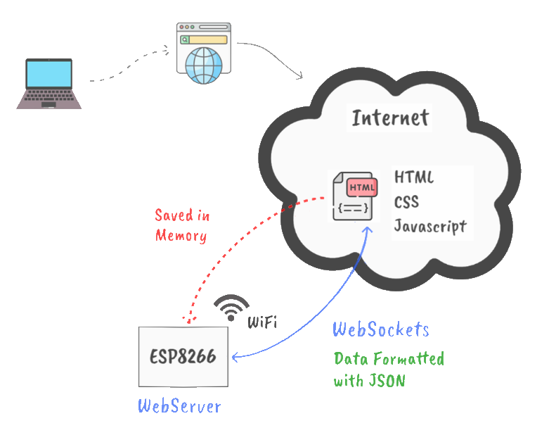
The ESP8266 is configured to work as a webserver, and is responsible to provide a webpage to any client that connects to it.
- Websockets are used to communicate between the ESP8266 and the webpage.
- Data is formatted using JSON to make it easier to handle different data types.
- The webpage is design using HTML and CSS
- Javascript is used to enable an interactive page and include the websockets code.
- The webpage is saved in the ESP8266 memory
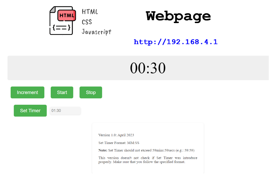
The webpage is rendered below.
The code that goes inside the ESP8266 is provided below.
// ---------------------------------------------------------------------------------------
//
// Code for a simple webserver on the ESP32 (device used for tests: ESP32-WROOM-32D).
// The code generates two random numbers on the ESP32 and uses Websockets to continuously
// update the web-clients. For data transfer JSON encapsulation is used.
//
// For installation, the following libraries need to be installed:
// * Websockets by Markus Sattler (can be tricky to find -> search for "Arduino Websockets"
// * ArduinoJson by Benoit Blanchon
//
// NOTE: in principle this code is universal and can be used on Arduino AVR as well. However, AVR is only supported with version 1.3 of the webSocketsServer. Also, the Websocket
// library will require quite a bit of memory, so wont load on Arduino UNO for instance. The ESP32 and ESP8266 are cheap and powerful, so use of this platform is recommended.
//
// Refer to https://youtu.be/15X0WvGaVg8
//
// Written by mo thunderz (last update: 27.08.2022)
//
// ---------------------------------------------------------------------------------------

//#include <WiFi.h>                                     // needed to connect to WiFi
#include <ESP8266WiFi.h>
//#include <WebServer.h>                                // needed to create a simple webserver (make sure tools -> board is set to ESP32, otherwise you will get a "WebServer.h: No such file or directory" error)
#include <ESP8266WebServer.h>
#include <WebSocketsServer.h>                         // needed for instant communication between client and server through Websockets
#include <ArduinoJson.h>                              // needed for JSON encapsulation (send multiple variables with one string)

// SSID and password of Wifi connection:
const char* ssid = "Kitchen Timer IoT";
const char* password = "";

// The String below "webpage" contains the complete HTML code that is sent to the client whenever someone connects to the webserver
String webpage = "<!DOCTYPE html><html><head><meta charset='UTF-8'> <title>Kitchen Timer IoT</title> <style>.container-timer{display: flex;flex-direction: row;justify-content: left;align-items: center;margin: 1rem;}.container-text {max-width: 500px;margin: 0 auto;padding: 2rem;box-shadow: 0px 2px 6px rgba(0, 0, 0, 0.1);background-color: #fff;border-radius: 0.5rem;line-height: 1;font-size: 1.2rem;color: #333;text-align: justify;text-justify: inter-word;word-wrap: break-word;}input[type='text'] {width: 10%;padding: 0.5rem;font-size: 1.2rem;border: none;border-radius: 0.5rem;box-shadow: 0px 2px 6px rgba(0, 0, 0, 0.1);background-color: #f5f5f5;font-family: Arial, sans-serif;transition: box-shadow 0.2s ease-in-out;}input[type='text']:focus {outline: none;box-shadow: 0px 4px 8px rgba(0, 0, 0, 0.2);} /* Style for the number display */ #number-display { font-size: 5rem; text-align: center; padding: 1rem; background-color: #eee; border-radius: 0.5rem; margin-bottom: 2rem; } /* Styles for the buttons */ .button { display: inline-block; background-color: #4CAF50; color: white; padding: 1rem 2rem; text-align: center; text-decoration: none; font-size: 1.5rem; margin: 0 1rem; cursor: pointer; border-radius: 0.5rem; border: none; } .button:hover { background-color: #3e8e41; } </style></head><body><p><div id='number-display'>00:00</div><button class='button' id='BTN_INC'>Increment</button><button class='button' id='BTN_START'>Start</button><button class='button' id='BTN_STOP'>Stop</button></p><div class='container-timer'><p><button class='button' id='BTN_SET'>Set Timer</button></p><input type='text' id='SET_TIME' placeholder='01:30'></div><div class='container-text'><p>Version 1.0: April 2023</p><p>Set Timer Format: MM:SS</p><p><b>Note:</b> Set Timer should not exceed 59mins:59secs (e.g.: 59:59)</p><p>This version doesn't not check if Set Timer was introduce properly. Make sure that you follow the specified format.</p></div></body><script> var Socket; document.getElementById('BTN_INC').addEventListener('click', button_inc); document.getElementById('BTN_START').addEventListener('click', button_start); document.getElementById('BTN_STOP').addEventListener('click', button_stop); document.getElementById('BTN_SET').addEventListener('click', button_set); function init() { Socket = new WebSocket('ws://' + window.location.hostname + ':81/'); Socket.onmessage = function(event) { processCommand(event); }; } function button_set() {var textBox = document.getElementById('SET_TIME'); var msg = {type: 'button_set',state: 'pressed',value: textBox.value};Socket.send(JSON.stringify(msg)); } function button_inc() { var msg = {type: 'button_inc',state: 'pressed'};Socket.send(JSON.stringify(msg)); } function button_start() { var msg = {type: 'button_start',state: 'pressed'};Socket.send(JSON.stringify(msg)); } function button_stop() { var msg = {type: 'button_stop',state: 'pressed'};Socket.send(JSON.stringify(msg)); } function processCommand(event) { var obj = JSON.parse(event.data);document.getElementById('number-display').innerHTML = obj.time;console.log(obj.time); } window.onload = function(event) { init(); }</script></html>";

// The JSON library uses static memory, so this will need to be allocated:
// -> in the video I used global variables for "doc_tx" and "doc_rx", however, I now changed this in the code to local variables instead "doc" -> Arduino documentation recomends to use local containers instead of global to prevent data corruption

// We want to periodically send values to the clients, so we need to define an "interval" and remember the last time we sent data to the client (with "previousMillis")
int interval = 1000;                                  // send data to the client every 1000ms -> 1s
unsigned long previousMillis = 0;                     // we use the "millis()" command for time reference and this will output an unsigned long

// Initialization of webserver and websocket
//WebServer server(80);                                 // the server uses port 80 (standard port for websites
ESP8266WebServer server(80);
WebSocketsServer webSocket = WebSocketsServer(81);    // the websocket uses port 81 (standard port for websockets

#define BUFF_SIZE 20
char  gIncomingChar;
char  gCommsMsgBuff[BUFF_SIZE];
int   iBuff = 0;
byte  gPackageFlag = 0;
byte  gProcessDataFlag = 0;

void setup() {

  pinMode(LED_BUILTIN, OUTPUT);
  digitalWrite(LED_BUILTIN, HIGH); // Turn it off

  // Init comms with Kitchen Timer
  Serial.begin(9600);

  WiFi.softAP(ssid, password); // Start the access point

  server.on("/", []() {                               // define here wat the webserver needs to do
    server.send(200, "text/html", webpage);           //    -> it needs to send out the HTML string "webpage" to the client
  });
  server.begin();                                     // start server

  webSocket.begin();                                  // start websocket
  webSocket.onEvent(webSocketEvent);                  // define a callback function -> what does the ESP32 need to do when an event from the websocket is received? -> run function "webSocketEvent()"
}

void loop() {

  server.handleClient();                              // Needed for the webserver to handle all clients
  webSocket.loop();                                   // Update function for the webSockets

  unsigned long now = millis();                       // read out the current "time" ("millis()" gives the time in ms since the Arduino started)
  if ((unsigned long)(now - previousMillis) > interval) { // check if "interval" ms has passed since last time the clients were updated

    // GET request
    Serial.print("$GET\n");

    // Get time through serial port
    gIncomingChar = Serial.read();

    // If start of the package
    if(gIncomingChar == '$')
    {
      // Clear Buffer
      for(int i=0; i<BUFF_SIZE; i++)
      {
        gCommsMsgBuff[i] = 0;
      }

      // set gCommsMsgBuff Index to zero
      iBuff = 0;

      gIncomingChar = Serial.read();
      while(gIncomingChar != '\n')
      {
        gCommsMsgBuff[iBuff] = gIncomingChar;
        iBuff++;
        gIncomingChar = Serial.read();

        if(iBuff == BUFF_SIZE)
        {
          gCommsMsgBuff[0] = 'x';
          gCommsMsgBuff[1] = 'x';
          gCommsMsgBuff[2] = ':';
          gCommsMsgBuff[3] = 'x';
          gCommsMsgBuff[4] = 'x';

          break;
        }
      }
    }
    // --------

    // Send time thtough websocket
    String jsonString = "";
    StaticJsonDocument<200> doc;
    JsonObject object = doc.to<JsonObject>();
    object["time"] = String(gCommsMsgBuff); //"54:47";
    serializeJson(doc, jsonString);
    webSocket.broadcastTXT(jsonString);
    // --------

    previousMillis = now;                             // reset previousMillis
  }
}

void webSocketEvent(byte num, WStype_t type, uint8_t * payload, size_t length) {      // the parameters of this callback function are always the same -> num: id of the client who send the event, type: type of message, payload: actual data sent and length: length of payload
  switch (type) {                                     // switch on the type of information sent
    case WStype_DISCONNECTED:                         // if a client is disconnected, then type == WStype_DISCONNECTED
      //Serial.println("Client " + String(num) + " disconnected");
      break;
    case WStype_CONNECTED:                            // if a client is connected, then type == WStype_CONNECTED
      //Serial.println("Client " + String(num) + " connected");
      // optionally you can add code here what to do when connected
      break;
    case WStype_TEXT:                                 // if a client has sent data, then type == WStype_TEXT
      // try to decipher the JSON string received
      StaticJsonDocument<200> doc;                    // create a JSON container
      DeserializationError error = deserializeJson(doc, payload);
      if (error) {
        //Serial.print(F("deserializeJson() failed: "));
        //Serial.println(error.f_str());
        return;
      }
      else {
        // JSON string was received correctly, so information can be retrieved:
        const char* g_type = doc["type"];
        const char* g_state = doc["state"];
        const char* g_value = doc["value"];

        if(strcmp(g_type, "button_set") == 0)
        {
          Serial.print("$SET,TMRS,");
          Serial.print(String(g_value));
          Serial.print("\n");
        }

        if(strcmp(g_type, "button_inc") == 0)
        {
          //Serial.print("$SET,TMRS,10:10\n");
          Serial.print("$INC\n");
        }

        if(strcmp(g_type, "button_start") == 0)
        {
          Serial.print("$STR\n");
        }

        if(strcmp(g_type, "button_stop") == 0)
        {
          Serial.print("$STP\n");
        }

        // -- Debug
        digitalWrite(LED_BUILTIN, LOW);
        delay(100);
        digitalWrite(LED_BUILTIN, HIGH);
        delay(100);
        // --

      }
      break;
  }
}
Sub Section 2: ATMEGA32U4 Code
The final ATMEGA32U4 code that integrates all the modules is provided below.
#include <Arduino.h>
#include <avr/power.h>

#define PF0   A5
#define PF1   A4
#define PF4   A3
#define PF5   A2
#define PF6   A1
#define PF7   A0

#define DIGIT_1   13  // PC7
#define RED_LED   5   // PC6
#define DIGIT_4   10  // PB6
#define DATA      9   // PB5 -> DS
#define LATCH     8   // PB4 -> ST_CP
#define BUZZER    6   // PD7
#define DIGIT_2   12  // PD6
#define GREEN_LED 4   // PD4

#define PD5       NotMappedPort_PD5 // Not Mapped on Leonardo Board
#define COMMS_TX  1                 // PD3 -> TX
#define COMMS_RX  0                 // PD2 -> RX
#define BUTTON_1  2                 // PD1 -> Start/Stop Timer and Stop Buzzer
#define BUTTON_2  3                 // PD0 -> Inc Timer
#define DIGIT_3   11                // PB7

#define PB3   NotMappedPort_PB3   // MISO -> Not Mapped on Leonardo Board
#define PB2   NotMappedPort_PB2   // MOSI -> Not Mapped on Leonardo Board
#define PB1   NotMappedPort_PB1   // SCK -> Not Mapped on Leonardo Board
#define PB0   NotMappedPort_PB0   // SS -> Not Mapped on Leonardo Board
#define CLOCK 7                   // PE6 -> SH_CP

// 7-Seg Display Variables
unsigned char gtable[]=
{0x3f,0x06,0x5b,0x4f,0x66,0x6d,0x7d,0x07,0x7f,0x6f,0x77,0x7c
,0x39,0x5e,0x79,0x71,0x00};
byte gCurrentDigit;

// Volatile Variables
volatile unsigned char gISRFlag1   = 0;
volatile unsigned char gISRFlag2   = 0;
volatile unsigned char gBuzzerFlag = 0;

// Timer Variables
#define       DEFAULT_COUNT 30     // default value is 30secs
volatile int  gCount        = DEFAULT_COUNT;
unsigned char gTimerRunning = 0;

unsigned int gReloadTimer1 = 62499; // corresponds to 1 second
byte         gReloadTimer3 = 200;   // display refresh time
unsigned int gReloadTimer4 = 100;   // corresponds to 0.4ms

#define BUFF_SIZE 20
char  gIncomingChar;
char  gCommsMsgBuff[BUFF_SIZE];
int   iBuff = 0;
byte  gPackageFlag = 0;
byte  gProcessDataFlag = 0;

unsigned char gDemoFlag = 0;

/**
 * @brief Setup peripherals and timers
 * @param
 * @return
 */
void setup() {

  if(F_CPU == 16000000) clock_prescale_set(clock_div_1);

  // LEDs Pins
  pinMode(RED_LED, OUTPUT);
  pinMode(GREEN_LED, OUTPUT);

  // LEDs -> Timer Stopped
  digitalWrite(RED_LED, HIGH);
  digitalWrite(GREEN_LED, HIGH);

  // Button Pins
  pinMode(BUTTON_1, INPUT_PULLUP);
  attachInterrupt(digitalPinToInterrupt(BUTTON_1), buttonISR1, RISING);
  pinMode(BUTTON_2, INPUT_PULLUP);
  attachInterrupt(digitalPinToInterrupt(BUTTON_2), buttonISR2, RISING);

  // Buzer Pins
  pinMode(BUZZER, OUTPUT);

  // Buzzer -> Off
  digitalWrite(BUZZER,LOW);

  // 7-Seg Display
  pinMode(DIGIT_1, OUTPUT);
  pinMode(DIGIT_2, OUTPUT);
  pinMode(DIGIT_3, OUTPUT);
  pinMode(DIGIT_4, OUTPUT);

  // Shift Register Pins
  pinMode(LATCH, OUTPUT);
  pinMode(CLOCK, OUTPUT);
  pinMode(DATA, OUTPUT);

  dispOff();  // turn off the display

  // UART Pins
  pinMode(COMMS_RX, INPUT);
  pinMode(COMMS_TX, OUTPUT);

  // timer4 should run faster than baudrate/8
  // 9600/8 = 1200 chars per second
  // 1/1200 = 0.833 ms
  Serial1.begin(9600);
  //Serial.begin(115200);  // Enable this for debug purposes

  // Initialize Timer1 (16bit) -> Used for clock
  // OCR1A = (F_CPU / (N * f_target)) - 1
  // Speed of Timer1 = (16e6 / (256 * 1)) - 1 = 62499
  noInterrupts();
  TCCR1A = 0;
  TCCR1B = 0;
  OCR1A = gReloadTimer1; // compare match register 16MHz/256
  TCCR1B |= (1<<WGM12);   // CTC mode
  // Start Timer by setting the prescaler -> done using the start button
  //TCCR1B |= (1<<CS12);    // 256 prescaler
  TIMSK1 |= (1<<OCIE1A);  // enable timer compare interrupt
  interrupts();

  // Initialize Timer3 (16bit) -> Used to refresh display
  // Speed of Timer3 = 16MHz/64 = 250 KHz
  TCCR3A = 0;
  TCCR3B = 0;
  OCR3A = gReloadTimer3;            // max value 2^16 - 1 = 65535
  TCCR3A |= (1<<WGM31);
  TCCR3B = (1<<CS31) | (1<<CS30);   // 64 prescaler
  TIMSK3 |= (1<<OCIE3A);
  interrupts();                     // enable all interrupts

  // Initialize Timer4 (10bit) -> Used for Serial Comms
  // Speed of Timer4 = 16MHz/64 = 250 KHz
  TCCR4A = 0;
  TCCR4B = 0;
  OCR4A = gReloadTimer4;            // max value 2^10 - 1 = 1023
  TCCR4A |= (1<<WGM41);
  TCCR4B = (1<<CS41) | (1<<CS40);   // 64 prescaler
  TIMSK4 |= (1<<OCIE4A);
  interrupts();                     // enable all interrupts
}

/**
 * @brief Shifts the bits through the shift register
 * @param num
 * @param dp
 * @return
 */
void display(unsigned char num, unsigned char dp)
{
  digitalWrite(LATCH, LOW);
  shiftOut(DATA, CLOCK, MSBFIRST, gtable[num] | (dp<<7));
  digitalWrite(LATCH, HIGH);
}

/**
 * @brief Turns the 7-seg display off
 * @param
 * @return
 */
void dispOff()
{
   digitalWrite(DIGIT_1, HIGH);
   digitalWrite(DIGIT_2, HIGH);
   digitalWrite(DIGIT_3, HIGH);
   digitalWrite(DIGIT_4, HIGH);
}

/**
 * @brief Button 2 ISR
 * @param
 * @return
 */
void buttonISR2()
{
  // Increment Clock
  gCount++;
}

/**
 * @brief Button 1 ISR
 * @param
 * @return
 */
void buttonISR1()
{
  // Set ISR Flag
  gISRFlag1 = 1;
}

/**
 * @brief Timer 2 ISR
 * @param TIMER2_COMPA_vect
 * @return
 */
ISR(TIMER3_COMPA_vect)   // Timer2 interrupt service routine (ISR)
{
  dispOff();  // turn off the display

  switch (gCurrentDigit)
  {
    case 1: //0x:xx
      display( int((gCount/60) / 10) % 6, 0 );   // prepare to display digit 1 (most left)
      digitalWrite(DIGIT_1, LOW);  // turn on digit 1
      break;

    case 2: //x0:xx
      display( int(gCount / 60) % 10, 1 );   // prepare to display digit 2
      digitalWrite(DIGIT_2, LOW);     // turn on digit 2
      break;

    case 3: //xx:0x
      display( (gCount / 10) % 6, 0 );   // prepare to display digit 3
      digitalWrite(DIGIT_3, LOW);    // turn on digit 3
      break;

    case 4: //xx:x0
      display(gCount % 10, 0); // prepare to display digit 4 (most right)
      digitalWrite(DIGIT_4, LOW);  // turn on digit 4
      break;

    default:
      break;
  }

  gCurrentDigit = (gCurrentDigit % 4) + 1;
}

/**
 * @brief Timer 1 ISR
 * @param TIMER1_COMPA_vect
 * @return
 */
ISR(TIMER1_COMPA_vect)  // Timer1 interrupt service routine (ISR)
{
  gCount--;

  if(gCount == 0)
  {
      // Stop Timer
      stopTimer1();

      // Raise Alarm
      gBuzzerFlag = 1;
      gTimerRunning = 0;
  }
}

/**
 * @brief Timer 4 ISR
 * @param TIMER4_COMPA_vect
 * @return
 */
ISR(TIMER4_COMPA_vect)  // Timer4 interrupt service routine (ISR)
{
  if(Serial1.available()>0)
  {
    gISRFlag2 = 1;
  }
}

/**
 * @brief Stop Timer 1
 * @param
 * @return
 */
void stopTimer1()
{
  // Stop Timer
  TCCR1B &= 0b11111000; // stop clock
  TIMSK1 = 0; // cancel clock timer interrupt
}

/**
 * @brief Start Timer 1
 * @param
 * @return
 */
void startTimer1()
{
  // Start Timer
  TCCR1B |= (1<<CS12);    // 256 prescaler
  TIMSK1 |= (1<<OCIE1A);  // enable timer compare interrupt
}

/**
 * @brief Turn On Buzzer
 * @param
 * @return
 */
void activeBuzzer()
{
  unsigned char i;
  unsigned char sleepTime = 1; // ms

  for(i=0;i<10;i++)
  {
    digitalWrite(BUZZER,HIGH);
    delay(sleepTime);//wait for 1ms
    digitalWrite(BUZZER,LOW);
    delay(sleepTime);//wait for 1ms
  }
}

char compareArray(char a[], char b[], int size)
{
  int i;
  char result = 1;  // default: the arrays are equal

  for(i = 0; i<size; i++)
  {
    if(a[i]!=b[i])
    {
      result = 0;
      break;
    }
  }
  return result;
}

/**
 * @brief Main Loop
 * @param
 * @return
 */
void loop()
{
  char  auxMsgBuff[BUFF_SIZE];
  int auxCount = 0;
  unsigned char auxDigit = '0';

  // Attend Button 2 ISR
  if(gISRFlag1 == 1)
  {
    // Reset ISR Flag
    gISRFlag1 = 0;

    if(gTimerRunning == 0)
    {
      // Start Timer
      gTimerRunning = 1;

      if(gCount == 0)
        gCount = DEFAULT_COUNT;

      if(gBuzzerFlag == 1)
      {
        gBuzzerFlag = 0;

        // LEDs -> Timer Stopped
        digitalWrite(RED_LED, HIGH);
        digitalWrite(GREEN_LED, HIGH);
      }
      else
      {
        startTimer1();
        // LEDs -> Timer Running
        digitalWrite(RED_LED, LOW);
        digitalWrite(GREEN_LED, HIGH);
      }
    }
    else
    {
      // Stop Timer
      stopTimer1();
      gTimerRunning = 0;

      // LEDs -> Timer Running
      digitalWrite(RED_LED, HIGH);
      digitalWrite(GREEN_LED, HIGH);
    }
  }

  // Attend gBuzzerFlag
  if(gBuzzerFlag == 1)
  {
    // Make Noise...
    digitalWrite(RED_LED, HIGH);
    digitalWrite(GREEN_LED, LOW);
    activeBuzzer();
  }

  // Attend Timer4 flag - receive commands through serial
  if(gISRFlag2 == 1)
  {
    // Reset ISR Flag
    gISRFlag2 = 0;

    // Read serial
    gIncomingChar = Serial1.read();

    // If normal character from package
    if(gPackageFlag == 1)
    {
      gCommsMsgBuff[iBuff] = gIncomingChar;
      iBuff++;

      // Safety mechanism in case "\n" is never sent
      if(iBuff == BUFF_SIZE)
      {
        gPackageFlag = 0;
        gProcessDataFlag = 1;
      }
    }

    // If start of the package
    if(gIncomingChar == '$')
    {
      gPackageFlag = 1;  // Signal start of package

      // Clear Buffer
      for(int i=0; i<BUFF_SIZE; i++)
      {
        gCommsMsgBuff[i] = 0;
      }

      // set gCommsMsgBuff Index to zero
      iBuff = 0;
    }

    // If end of package
    if( (gIncomingChar == '\n') && (gPackageFlag == 1) )
    {
      // Signal end of package
      gPackageFlag = 0;
      gProcessDataFlag = 1;
    }
  }

  // Process serial commands
  if(gProcessDataFlag == 1)
  {
    gProcessDataFlag = 0;
    //Serial.print(gCommsMsgBuff);  // TMP

    // Get Command
    if(compareArray(gCommsMsgBuff, "SET", 3) == 1)
    {
      // Get Function
      auxMsgBuff[0] = gCommsMsgBuff[4];
      auxMsgBuff[1] = gCommsMsgBuff[5];
      auxMsgBuff[2] = gCommsMsgBuff[6];
      auxMsgBuff[3] = gCommsMsgBuff[7];

      if(compareArray(auxMsgBuff, "ALRM", 4) == 1)
      {
        // Get Value
        if(gCommsMsgBuff[9] == '0')
        {
          // turn off alarm function
          gBuzzerFlag = 0;
        }else
        {
          // turn on alarm function
          gBuzzerFlag = 1;
        }
      }

      if(compareArray(auxMsgBuff, "RLED", 4) == 1)
      {
        // Get Value
        if(gCommsMsgBuff[9] == '0')
        {
          // turn off red led function
          digitalWrite(RED_LED, LOW);
        }else
        {
          // turn on red led function
          digitalWrite(RED_LED, HIGH);
        }
      }

      if(compareArray(auxMsgBuff, "GLED", 4) == 1)
      {
        // Get Value
        if(gCommsMsgBuff[9] == '0')
        {
          // turn off green led function
          digitalWrite(GREEN_LED, LOW);
        }else
        {
          // turn on green led function
          digitalWrite(GREEN_LED, HIGH);
        }
      }

      if(compareArray(auxMsgBuff, "TMRS", 4) == 1)
      {
        auxCount = 0;
        // Get Time and conver to second
        auxCount += int(gCommsMsgBuff[9] - '0')*10*60;  // 0x:xx
        auxCount += int(gCommsMsgBuff[10] - '0')*60;    // x0:xx
        auxCount += int(gCommsMsgBuff[12] - '0')*10;    // xx:0x
        auxCount += int(gCommsMsgBuff[13] - '0');       // xx:x0
        // convert to seconds
        // affect gCount
        //Serial.println("Set Timer Value");
        gCount = auxCount;
      }
    }

    if(compareArray(gCommsMsgBuff, "STR", 3) == 1)
    {
      // Start timer function
      startTimer1();
    }

    if(compareArray(gCommsMsgBuff, "STP", 3) == 1)
    {
      // Stop timer function
      stopTimer1();
    }

    if(compareArray(gCommsMsgBuff, "INC", 3) == 1)
    {
      // Increment Timer
      gCount++;
    }

    if(compareArray(gCommsMsgBuff, "GET", 3) == 1)
    {
      // Send clock status
      Serial1.print("$");

      auxDigit = int((gCount/60) / 10) % 6;
      Serial1.print(String(auxDigit));

      auxDigit = int(gCount / 60) % 10;
      Serial1.print(String(auxDigit));

      Serial1.print(":");

      auxDigit = (gCount / 10) % 6;
      Serial1.print(String(auxDigit));

      auxDigit = gCount % 10;
      Serial1.print(String(auxDigit));
      Serial1.print("\n");
    }
    // ------
  }
}
Enclosure Design
This section focus on the design and fabrication of an enclosure for the Kitchen Timer.
Note: normally this phase is done in conjunction with a marketing or product design team and it should be done before any PCB components routing. This is to make sure that output, input, and display connectors at the desired place.
Enclosure 3D Render
The material for this enclosure can be any material from plastic to wood. The render below is using wood texture for the enclosure and acrylic for the face plate.
Dimensions
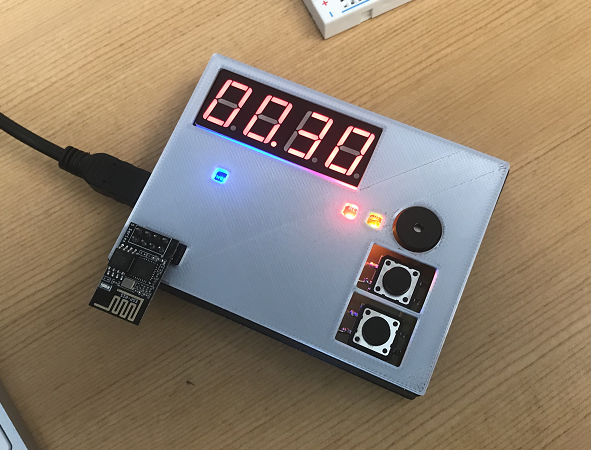
3D Printed Model
Enclosure and face plate printed with a 3D printer.
Students Phase B Boards
Below you can find the boards produced by the students of the Embedded System Class 2022/2023. Overall, 27 boards were sent to the fabrication house (PCBWay) and 25 boards were assembled by the students.
Out for 25 boards, 13 boards are fully functional (videos of an LED blinking below).

Unfortunately, the other boards had some sort of design or assembly mistake that prevented the boards to work properly. Some potential issues below:
- Decoupling capacitors faraway from the VCC pins of the microprocessor
- Crystal too faraway from the microprocessor
- The capacitors for the crystal are faraway from the crystal
- USB connector is unreachable.
- Potentially too much heat applied to the microprocessor while soldering it to the PCB
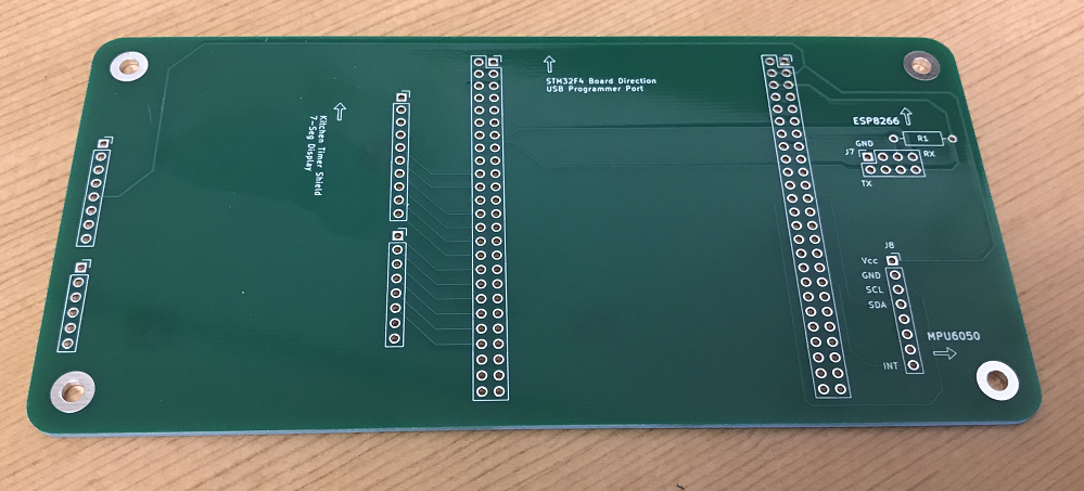
Phase C: Final Iteration
If we want to add additional sensors/actuators (e.g.: IMU, vibration motor, etc) or add other code features to the Kitchen Timer, we probably need to move to a microprocessor that has more GPIOs available and potentially runs faster.
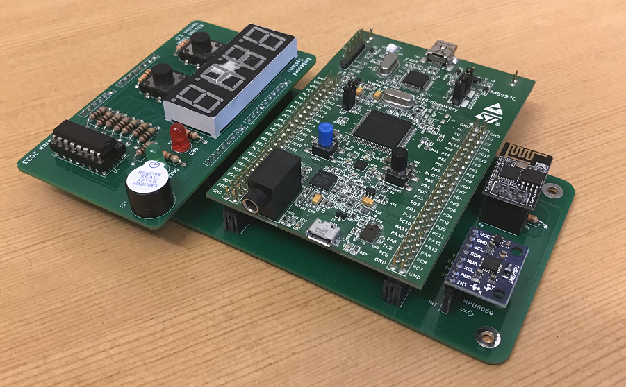
For this last Phase, we will be using an Arm Cortex-M4 32-bit core. We will be using the STM32F4 Discovery Board for the prototype stage and make sure that the code is ported accordingly from Phase B. After that we will add an additional sensor, the IMU MPU6050 and respective code.
STM32F4 Discovery Board Introduction
The STM32F4 Discovery Kit has a good portion of peripherals already available for the user to explore, namely, 3 axis accelerometer, 4 user LEDs, 1 user button, a 3.5mm audio jack, chip microphone and an USB OTG.
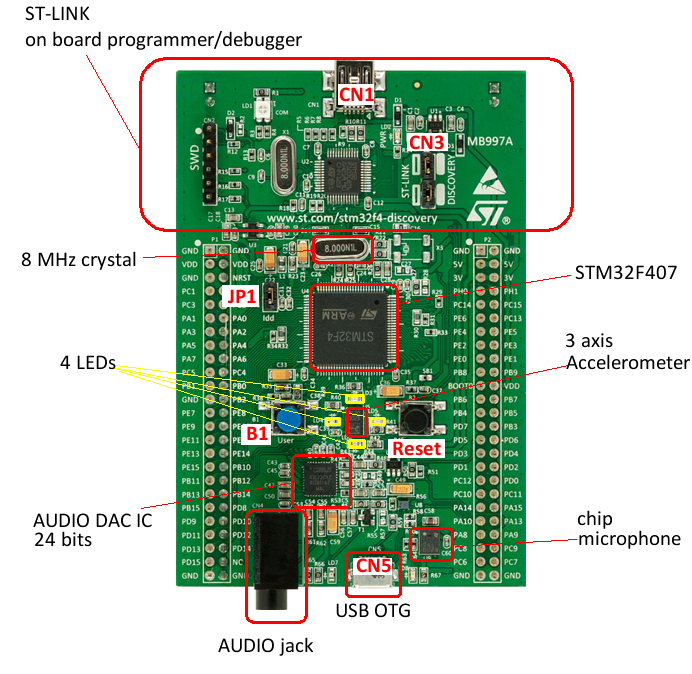
For this project, we will be using only the user LEDs and the rest of the peripherals will be disabled in software accordingly. However, the components are still connected physically to the pinouts.
While mapping the Kitchen Timer Shield components to this board, we will avoid using the pins that have external components attached, in order to avoid conflict while coding the STM32F4 later.
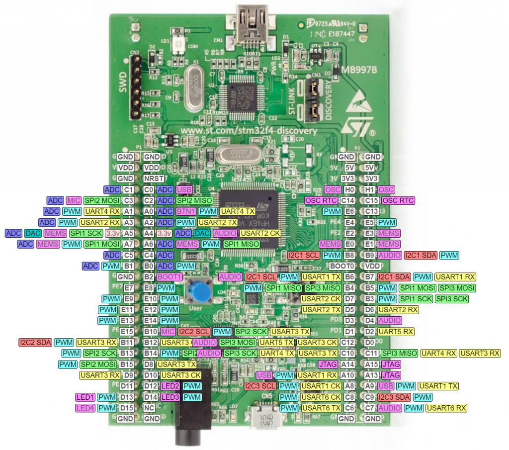
Pinout
The images below, are from the Espruino Website [REF 2]. The documentation on this website is stellar and very well organized. We can select any pin besides the ones in purple since they have a functionality on the board already. For this project, we should also avoid selecting the pins that are not 5v tolerant.
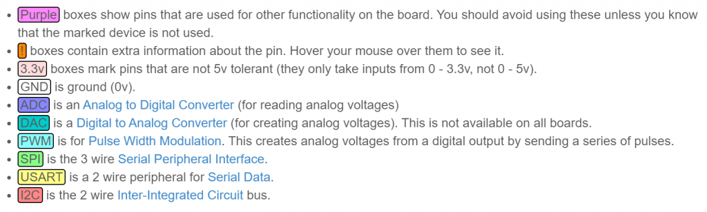
(Zoom)
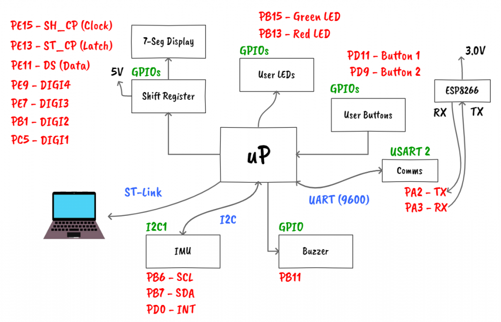
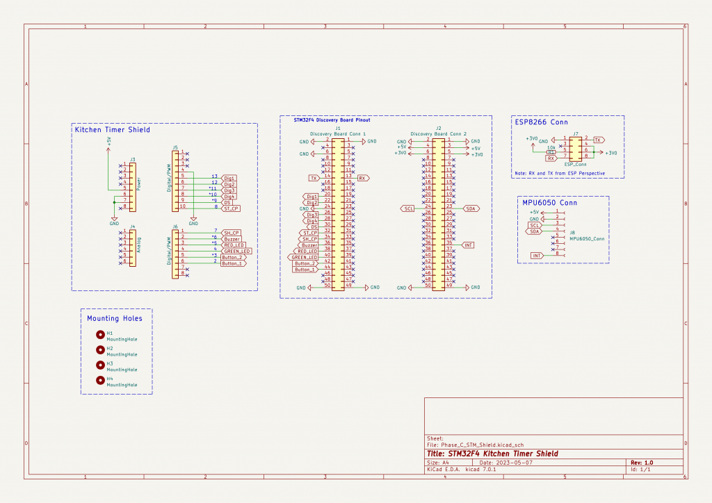
System Design
As always, let's start with a draft of the system block diagram. The blocks are pretty much the same as the blocks for Phase B. The pinouts were mapped to the STM32F4 Discovery Board peripherals (Link).
Note: I want to clarify that this design was not done in one go. In fact it took several iterations and it was adjusted at the same time as the code was being developed. What you see below, is the final iteration of the design.
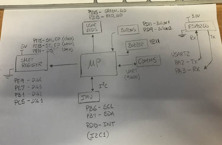
If possible, we can polish and clean up the block diagram.
Note: you can select other pins, as long as you change the code accordingly later. I selected these ones because they made my life easier while routing the wires on the PCB board shield for this phase.
Component Selection
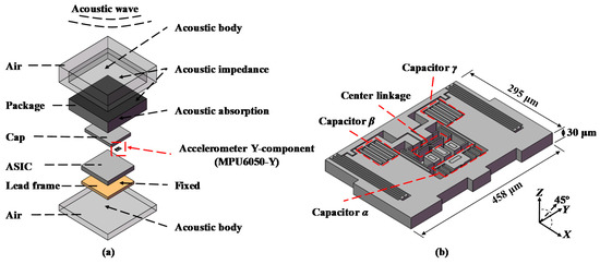
The new sensor for this phase is the MPU6050. I picked this sensor because it is one of the most common IMU modules used in Arduino projects and it is relatively affordable (~$7). The MPU6050 integrates 3-axis gyroscope 3-axis accelerometer, and a Digital Motion Processor (DMP). It can measure angular momentum or rotation along all 3 axis, static acceleration caused by gravity, and dynamic acceleration caused by motion, shock or vibration.
[REF 3] does a fantastic job introducing this device, going into detail on the micro-machined structure built on top of a silicon wafer to sense accelerations and angular rotations.
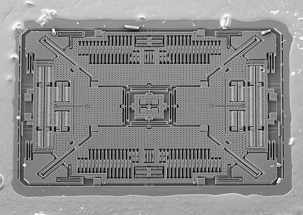
[REF 4] shows an acoustic injection study on the MPU6050 that is also interesting to read and learn more about the internals of this module.
We will get back to the sensor later during the Software Development section.
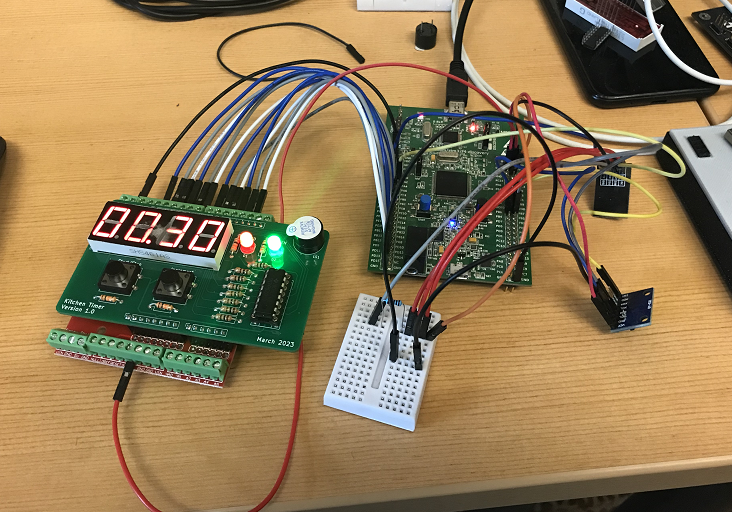
Build Prototype
This stage might not be possible to do for some projects, but if possible, it is always good to test the components first before building the PCB.
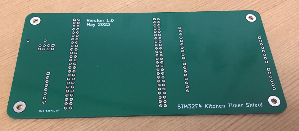
PCB Design
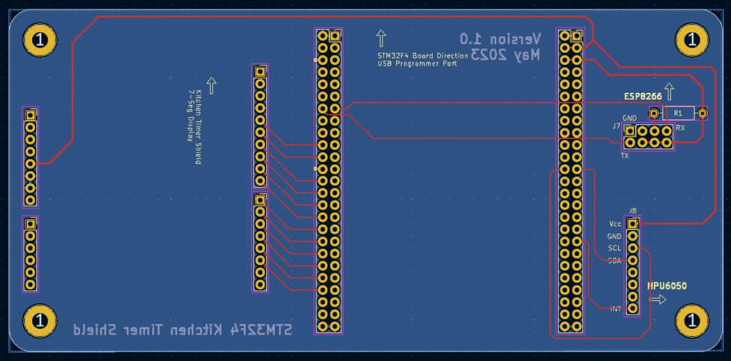
Assemble Stage
Software Development
Soon...
GitHub Repository
Phase A Code (Arduino Uno Compatible)
Phase B Code (Arduino Leonardo Compatible)
- BlinkLED
- Clock code with Interrupts (no Comms)
- Clock code with FreeRTOS (no Comms)
- Clock code with Interrupts (complete)
- ESP8266 Code
Phase C Code (STM32F4 Discovery Board Compatible)
- Clock code (no IMU) - soon
- Clock code with IMU - soon
References
- [Ref 1] “Switch Debouncing for Electronic Product Designs”, Nuvation Engineering Website [Article]
- [Ref 2] “STM32 F4 Discovery - Interactive Pinout”, Espruino Website [Article]
- [Ref 3] “Interface MPU6050 Accelerometer and Gyroscope Sensor with Arduino”, Last Minute Engineers Website [Article]
- [Ref 4] “Investigation of Acoustic Injection on the MPU6050 Accelerometer”, Sensors 2019 [Article]
- [Ref 5] “How to Implement Hardware Debounce for Switches and Relays When Software Debounce Isn’t Appropriate”, Digi-Key Website [Article]
Sponsor