LTSpice Dependent Sources
Introduction
An ideal dependent (or controlled) source is an active element in which the source quantity is controlled by another voltage or current.
There are 4 different types of dependent sources:
- VCVS – Voltage Control Voltage Source
- CCVS – Current Control Voltage Source
- VCCS – Voltage Control Current Source
- CCCS – Current Control Current Source
Let’s learn this by example.
VCVS
The schematic symbol for a voltage control voltage source is the following:
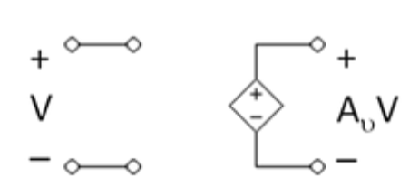
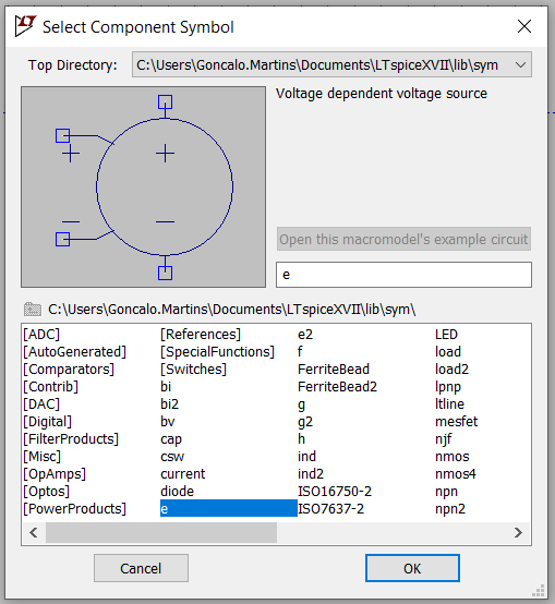
In LTspice the “e” component represents a VCVS.
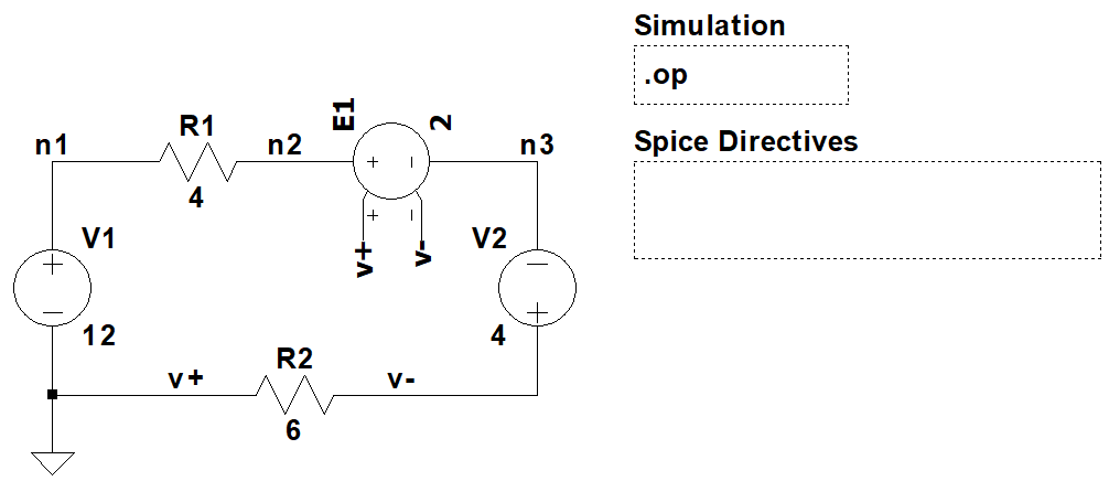
Circuit example:
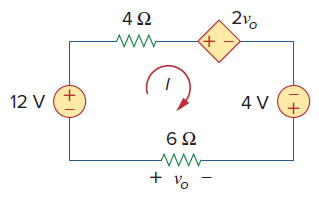
To make the schematic easier to read, we use labels instead of wires to connect the VC terminals of “e” to the desired nodes.
Note: Be aware if you place the ground reference at a different node, you will get different results for the voltage at the other nodes. Currents will be the same independently where you place the ground reference.
VCCS
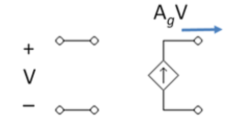
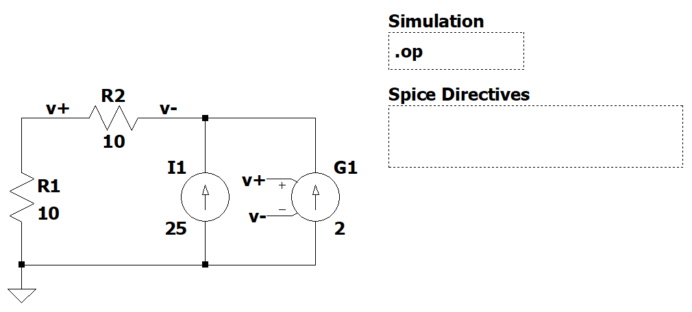
The schematic symbol for a voltage control current source is the following:
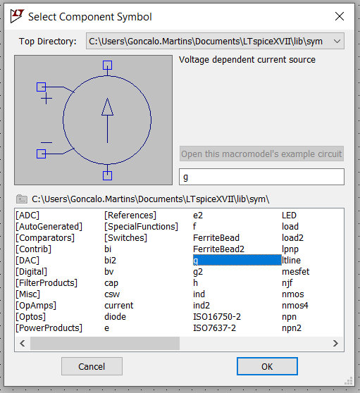
In LTspice the “g” component represents a VCCS.
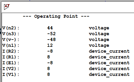
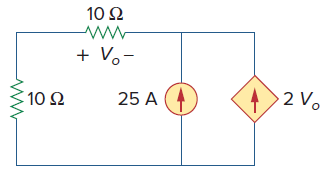
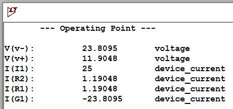
Circuit example:
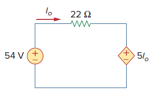
CCVS
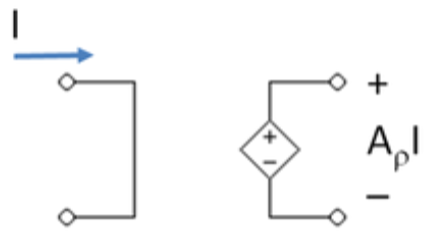
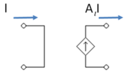
The schematic symbol for a current control voltage source is the following:
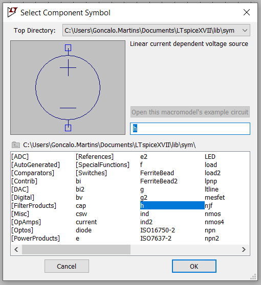
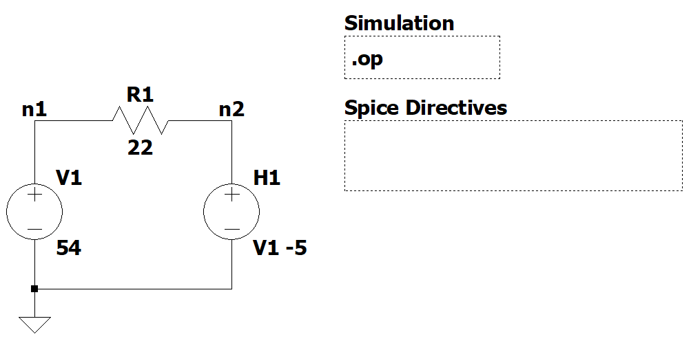
In LTspice the “h” component represents a CCVS.
Note: The “h” component requires a current through a voltage source. If the controlled current of your circuit doesn’t come from a voltage source, there are ways to work around this. Check Example 2 under Other Examples to see how to address that issue for a CCVS.
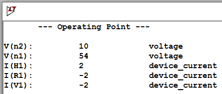
Circuit example:
CCCS
The schematic symbol for a current control current source is the following:
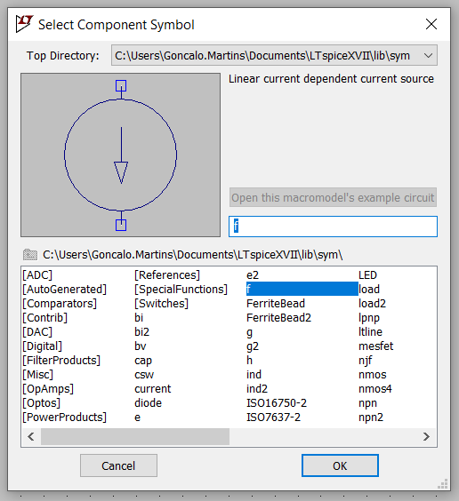
In LTspice the “f“ component represents a CCCS.
Note: The “f” component requires a current through a voltage source. If the controlled current of your circuit doesn’t come from a voltage source, there are ways to work around this. Check Example 1 under Other Examples to see how to address that issue for a CCCS.
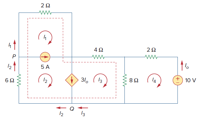
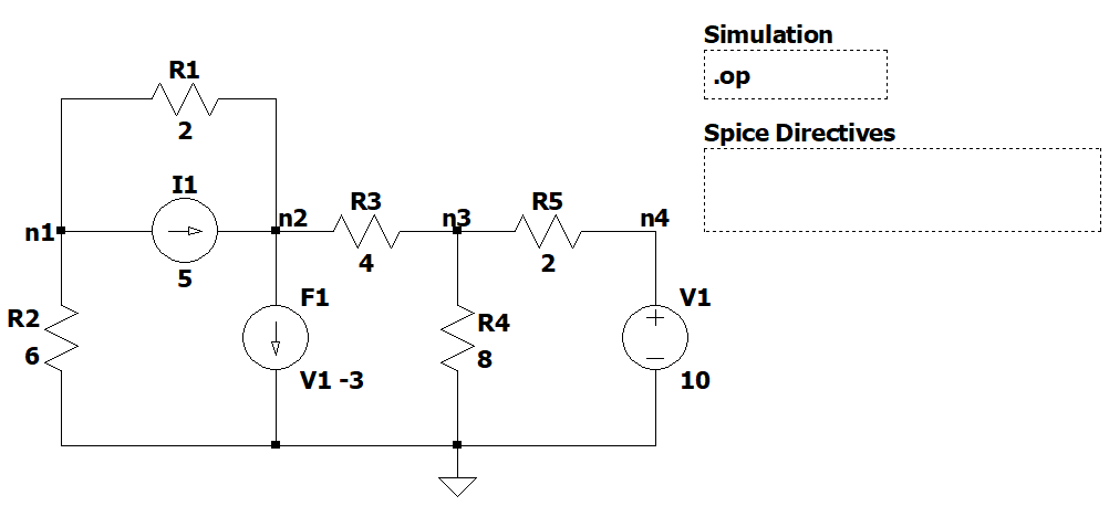
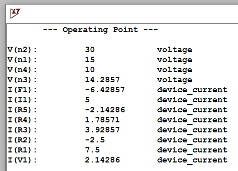
Circuit example:
Other Examples
Example 1
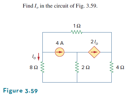
For CCCS dependent sources in LTSpice the “f” component requires a controlled current through a voltage source. For this particular example, the controlled current is related to a resistor. There are a couple of ways to simulate this situation.
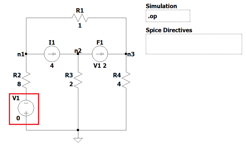
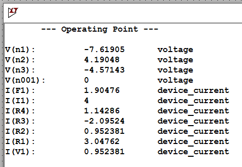
Option 1
Include a voltage source of 0V on the branch where the controlled current is present. The direction of this voltage source should have the controlled current entering the negative side of it.
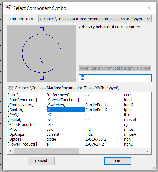
Option 2
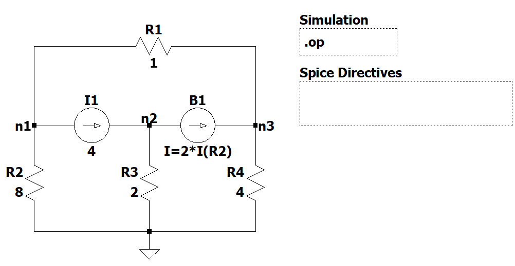
You can also use the arbitrary behavioral current source “bi”.
Example 2
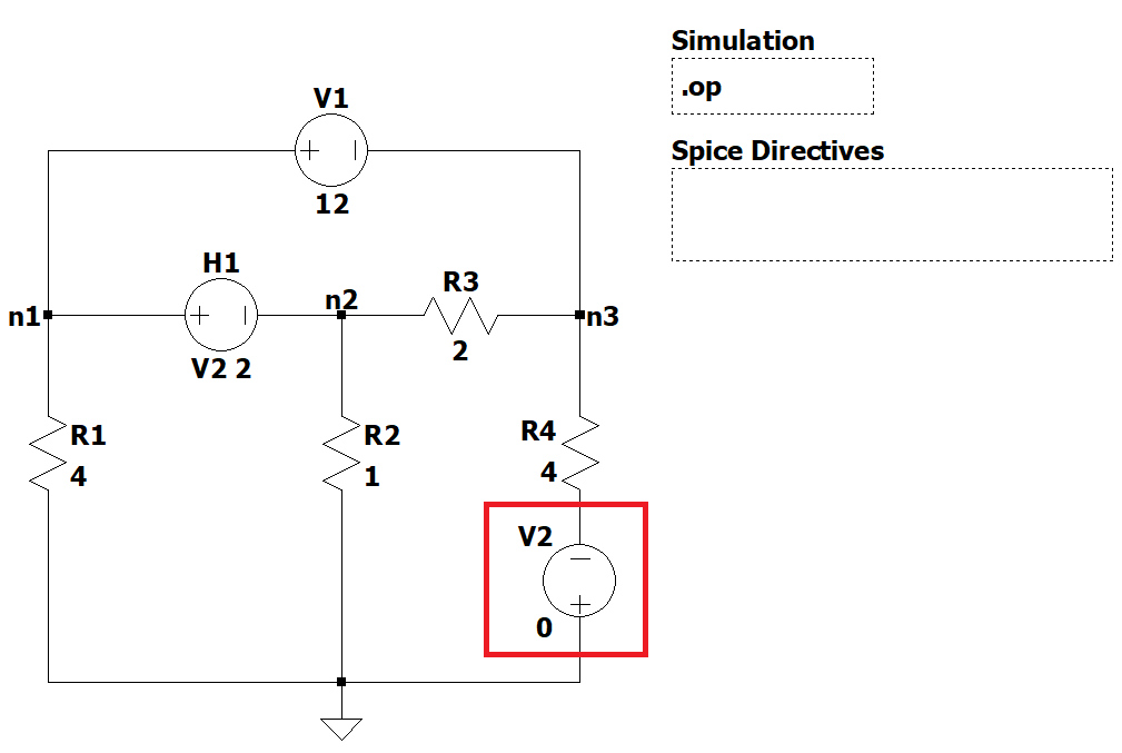
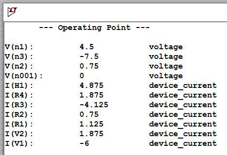
For CCVS dependent sources in LTSpice the “h” component requires a controlled current through a voltage source. For this particular example, the controlled current is related to a resistor. There are a couple of ways to simulate this situation.
Option 1
Include a voltage source of 0V on the branch where the controlled current is present. The direction of this voltage source should have the controlled current entering the negative side of it.
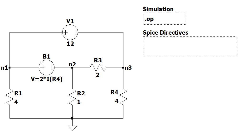
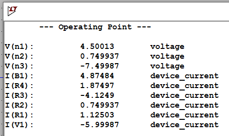
Option 2
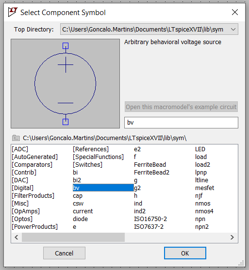
You can also use the arbitrary behavioral voltage source “bv”.
LTSpice Simulation Files
References
- [Ref 1] “LTspice tutorial – Ep7 Dependent voltage and current sources“, FesZ Electronics YouTube Channel [Video]