Logisim Evolution Synthesis and Download
Part 2: Logisim Evolution Synthesize and Donwload
Let's use an example to illustrate the process of synthesizing and deploying the code into a board in Logisim Evolution.
Block Diagram
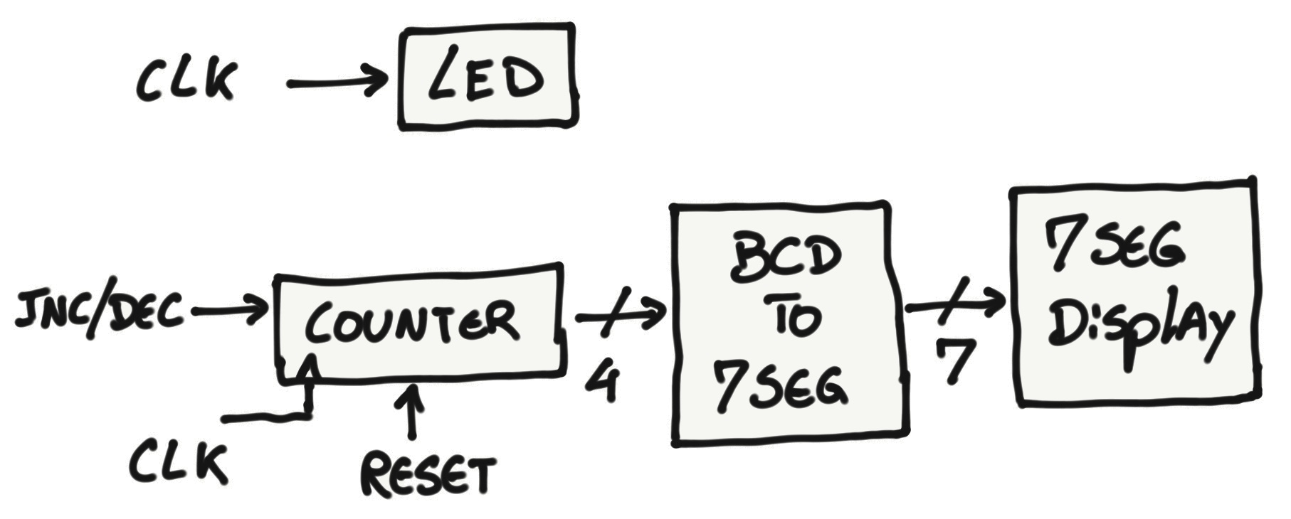
We will be implementing the logic to run two main blocks of hardware in parallel.
- The first block is an LED that blinks at the rate of a clock signal.
- The second block is a 4 bit counter in which the output binary number gets converted to be displayed into a 7 segment display. The counter has 3 inputs, a clock signal (to increment the counter), a Inc/Dec bit (to set the counter to increment or decrement the output value), and a reset bit (to clear the counter back to zero).
Design
If you are familiar with Logisim Evolution, you can replicate the system below.
(Logisim Evolution Project File)
If you need additional guidance, follow Block 1 and 2 description below.
Block 1
Let's start with the LED and clock modules.
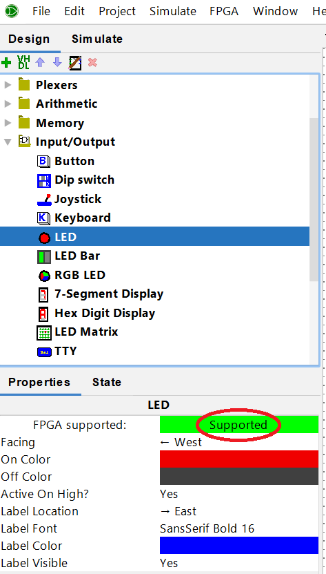
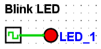
For the LED, go to the Input/Output folder and select the LED module. Notice that this module is FPGA supported. That means that Logisim Evolution is capable of synthesizing it.

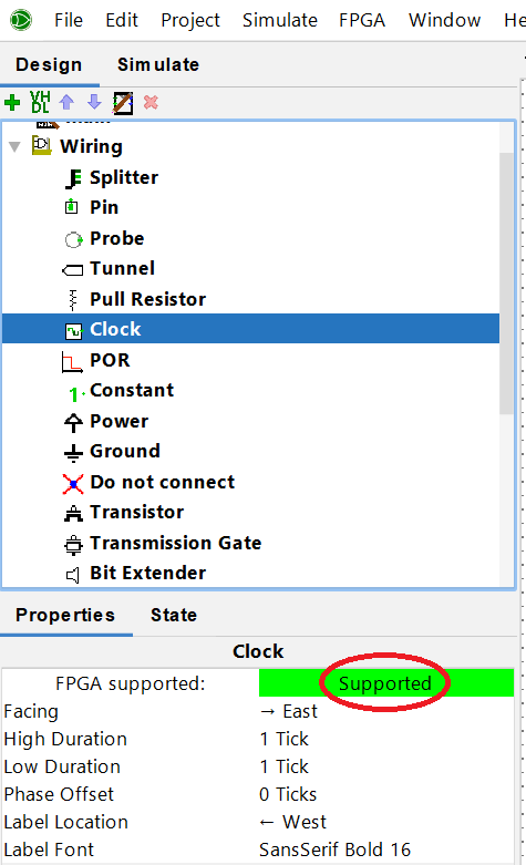
Next, go to the wiring folder and select the clock module. It is also FPGA supported. The rest of the parameters you can play around with them later. For now, leave it the way that it is.

Connect those two modules together.
Block 2
Now let's describe the counter, BCD to 7 seg, the 7 seg display, inputs/buttons and some additional glue logic modules.
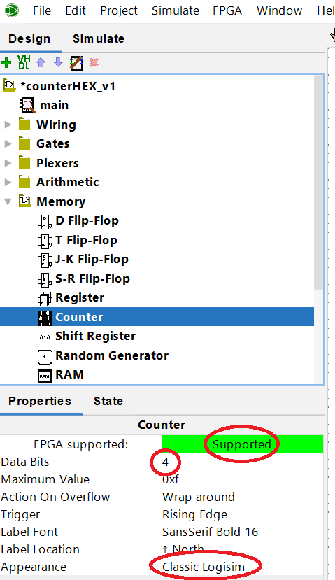
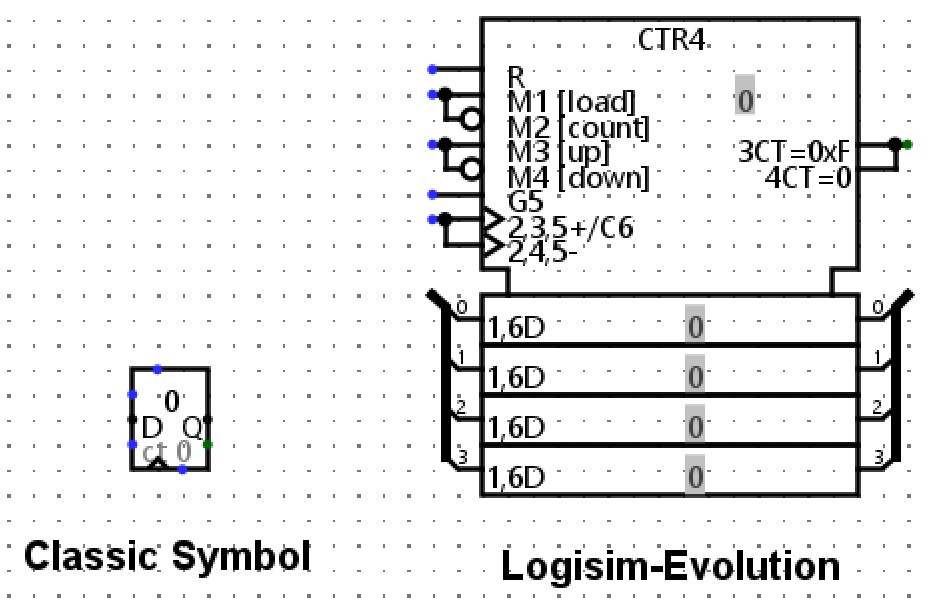
For the counter we will use the counter module under the Memory folder. This module is also FPGA supported. We set up the counter to be 4 bits and we will use the classic Logisim appearance.
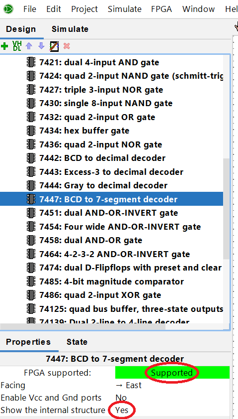
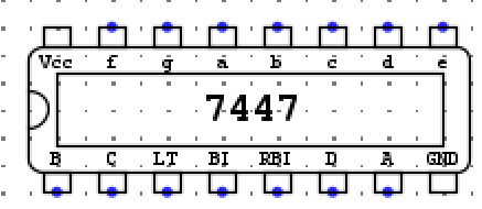
For the module that will convert the binary value coming out of the counter to a 7 segment display, we will use the TTL 7447 BCD to 7-sgment decoder (under the TTL folder). It is a module that is also FPGA supported and we set the internal structure visible so we can see the pinouts while connecting things around.
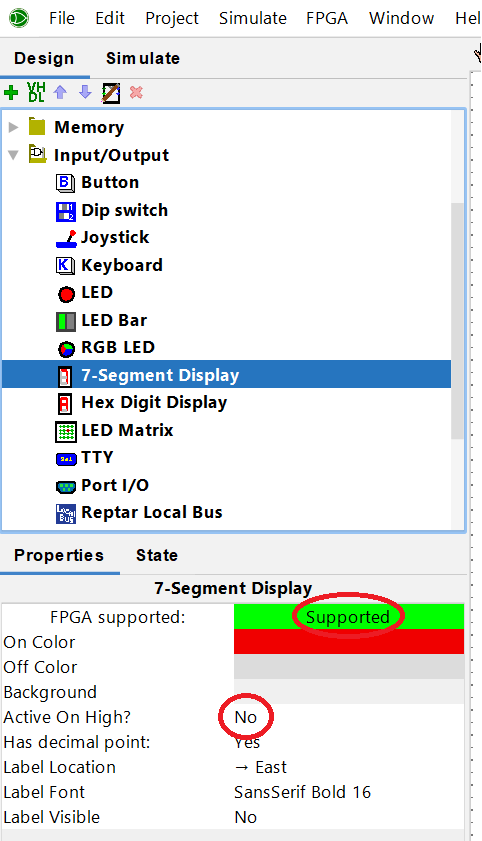
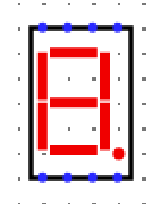
The last module is the 7 segment display. You can find that module under the Input/Output folder. It is also FPGA supported. The "Active On High?" parameter is only important for simulation purposes. You need to adjust the logic around the 7 seg display module according to the physical 7 seg display that you have available in your FPGA board.
Connect all 3 modules together.
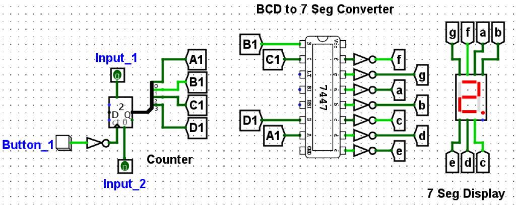
You probably notice additional modules connecting the main modules together.
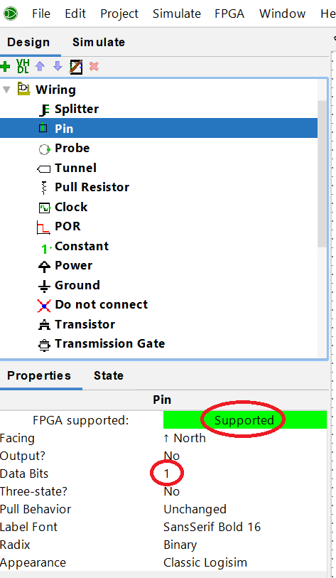
When connecting modules together, you can use wires or you can use labels (called Tunnel in Logisim). Using Tunnels provides a cleaner design and it is easier to follow the signals in your schematic. Tunnels can have more than 1 bit. However, for this example, we set the Tunnels to 1 bit.
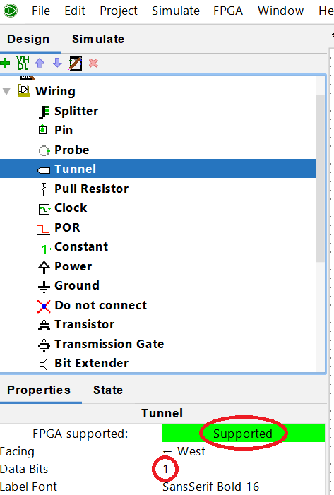
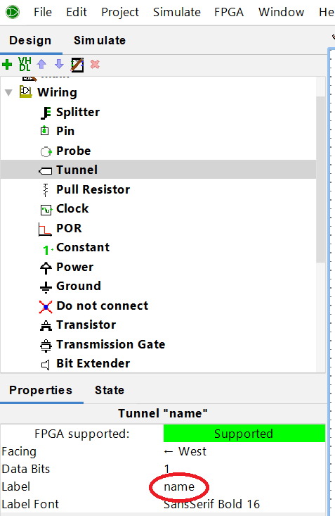
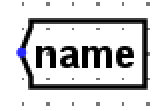
A Tunnel by default does not have a label associated with it. You need to add that label description after you add the tunnel into your design. Select the tunnel and change the label parameter to the desired name.
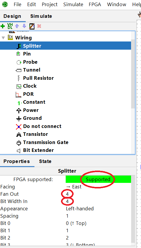
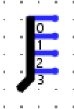
Another wiring module that can be useful is called Splitter. You can think about this module has a way to combine bits into a bus wire or have access to bits from a bus wire. For this example, the counter module provides 4 output bits into a single bus wire. We need to route those individual bits to the respective input of the TTL 7447. The splitter can be used to achieve that. The "Bit Width In" parameter, tells you the size of the bus wire and the "Fan Out" parameter tells you how many bits you want to have on the other side of the splitter.
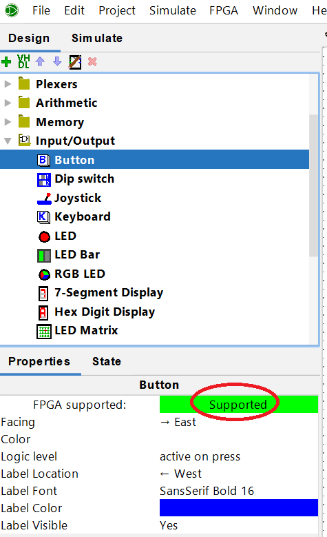
To interact with the system, we add buttons and inputs around the counter.


You also notice the addition of NOT gates around the circuit. These NOT gates are added specifically to make sure that the circuit works with the board that we will be using later to deploy the synthesis (DE10-Lite).
NOT Gate by “Button_1” Label
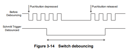
- KEY0 from the DE10-Lite board has a Schmitt Trigger circuit that "introduces hysteresis to the input signal for improved noise immunity, especially for signal with slow edge rate and act as switch debounce" (Page 25). This feature is useful if we want to use KEY0 to increment the counter and eliminate the jitter present when the button is pressed or released.
- However, KEY0 is active low (Page 25).
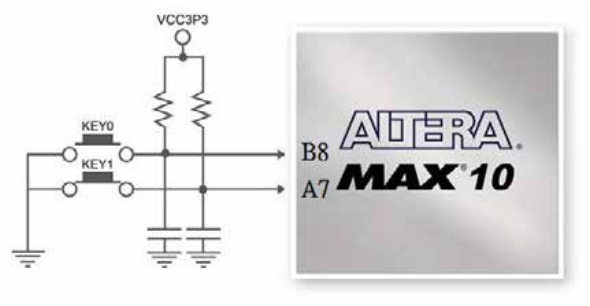
- "Button_1" label will be assigned later to KEY0 and it is controlling the clock of the counter module. Because the counter is set to count on the rising edge of the clock connecting a NOT gate in from of the button will make sure that the counter will count when the user presses the button, rather then when releasing the button.
NOT Gate on the Output of the TTL 7447
- The 7 seg display on the physical board has a common anode (positive terminal) among all LEDs in it (Page 29). That makes the 7 seg display an active low circuit. The LEDs on the 7 seg display will turn on at 0 rather than at 1. The TTL 7447 needs to invert the output in order to make sure that we see the right number on the display.
Simulation
Simulation is out of the scope for this article and we will not go over timing diagrams or test vectors for this example.
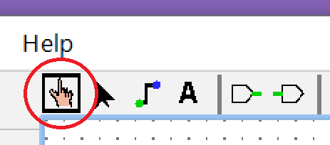
We are going to keep it simple for now. Select the "hand tool" and press the buttons and see if the circuit behaves as expected. To enable and disable the clock, press "ctrl + k".
Synthesis and Download
We got to the important part of this article. From this point, the steps are the same for any circuit that you develop in Logisim Evolution.
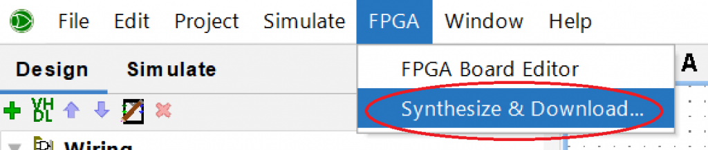
Go to the FPGA menu and select "Synthesize & Download".
You will be presented with the window below and we will cover the Settings, Annotate and Execute buttons next.
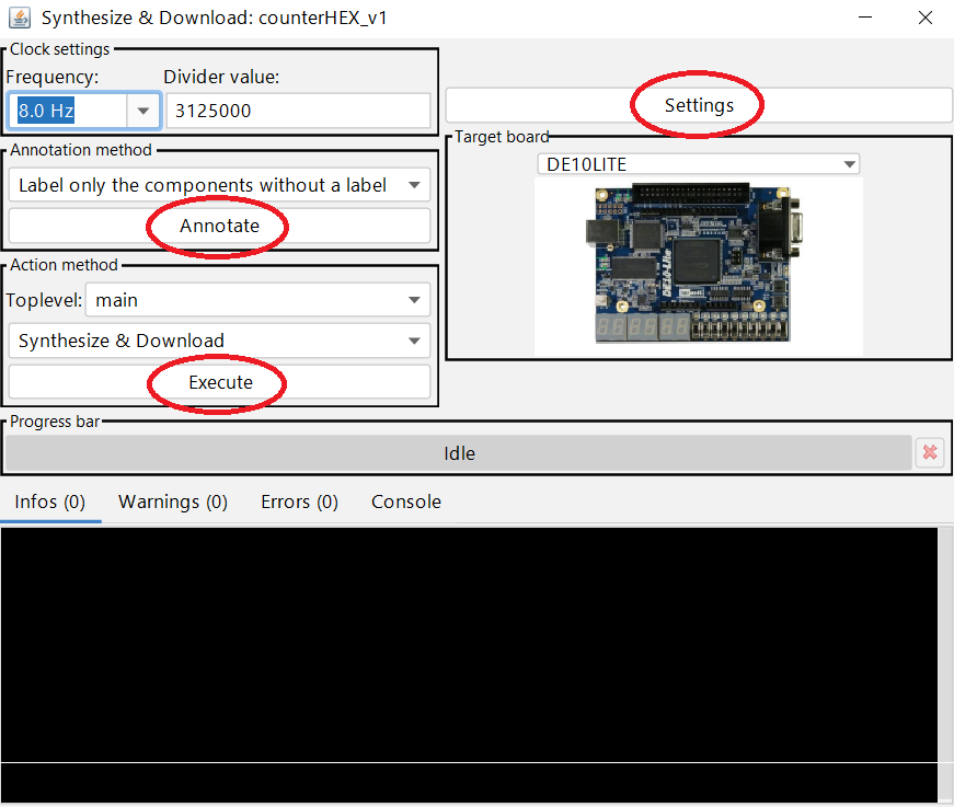
Settings and Target Board
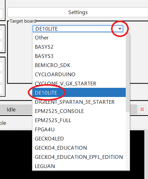
Select the board that you want to work with.
We are using the DE10LITE board. This board does not come by default in Logisim Evolution. But don't worry, on Part 3 of this tutorial, we show how to add boards to Logisim Evolution :).
After selecting the board, press on the "Settings" button.
From this new window, we will be covering the "Software", and the "FPGA Commander Settings" tabs. We cover the "External FPGA Board list" on Part 3 of this tutorial.
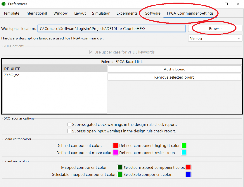
From the "FPGA Commander Settings" tab, press the "Browse" button and set the workspace location to where you saved your project. This is an important step to keep your projects organized.

Note: Make sure that you change this location for every new project that you synthesize. Otherwise, when you synthesize your new project it will save the new files into your previous project.
This next step, you only need to do it once. Go to the "Software" tab and make sure that you set the path under "Altera/Intel Quartus toolpath" and/or the path under "Xilinx Vivado toolpath" to point to where you have Vivado and Quartus installed in your computer.
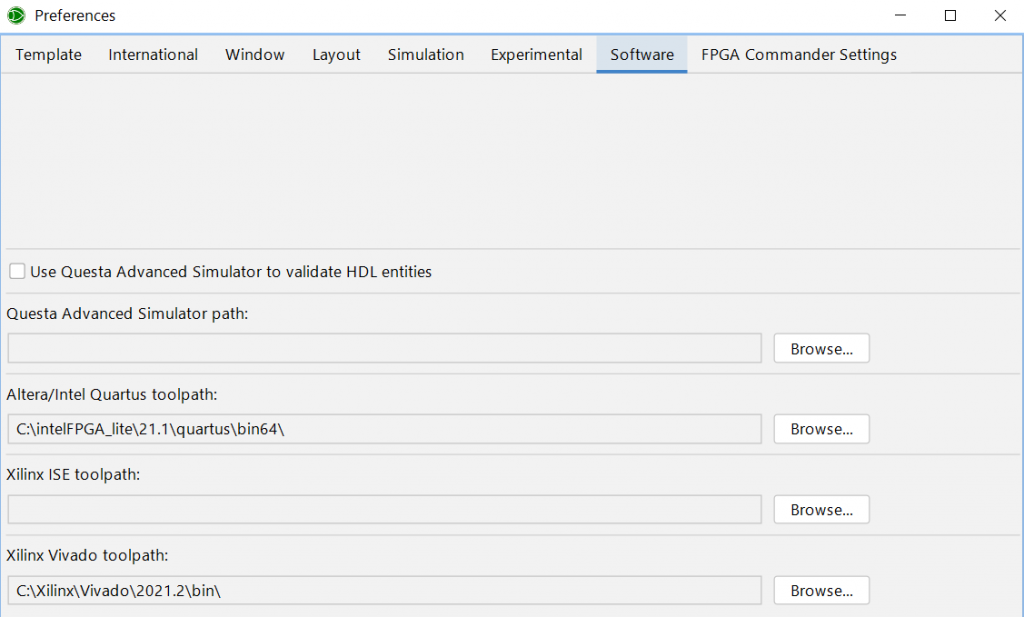
You need to have the software installed in your computer for the board that you are interested in deploying the code. If you are not dealing with Xilinx boards, no need to install Vivado or vice versa.
We are done with the settings menu.
Annotate
Annotate deals with labeling all the inputs (e.g. buttons) and outputs (e.g. LEDs). You can label the inputs and outputs manually while you are building the schematic or you can have Logisim label those for you.
In this example, we had Logisim labeling the buttons, inputs and LED automatically.
If you don't do this step, the Execute command will not work.
Execute
The last step is to synthesize your design and download it to the board.
We can choose to generate HDL, or Synthesize and Download, or Download. We will be synthesizing and downloading the code to the board.
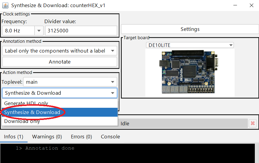
Connect the board to your computer and press the "Execute" button.
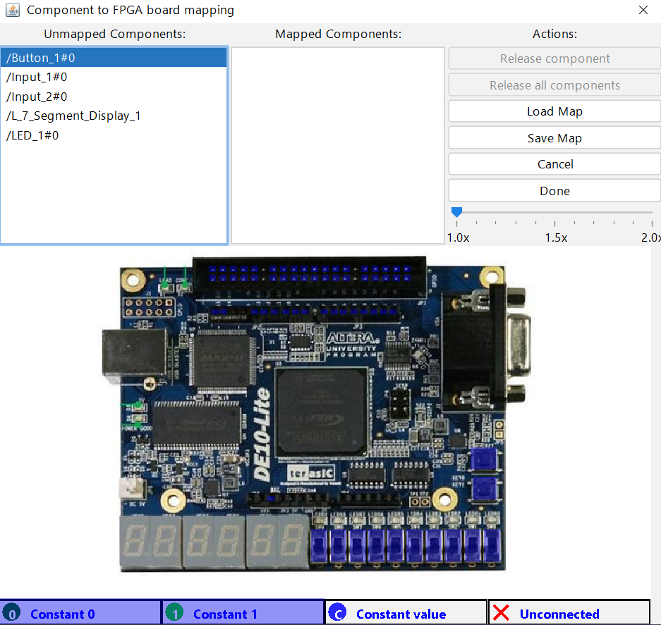
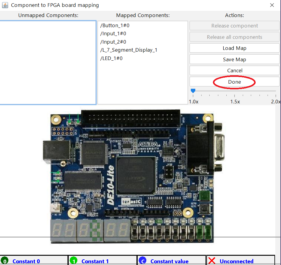
Now it is time to map the pinouts to the physical board. Select each pin individually and assign it to a physical switch, or button, or LED, or 7 seg display accordingly.
Once you are done, press the "Done" button.
Logisim Evolution starts with performing the synthesis using Quartus software underneath it. This process can take a while depending on the size or complexity of your design.
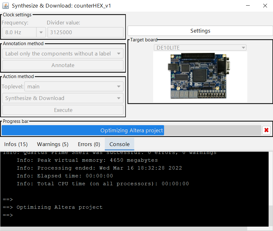

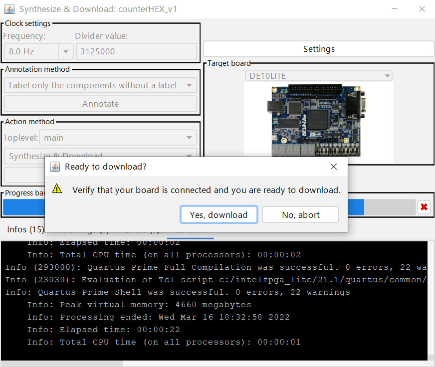
After optimizing and generating the bit file, Logisim asks if you want to download the bit stream to the FPGA.
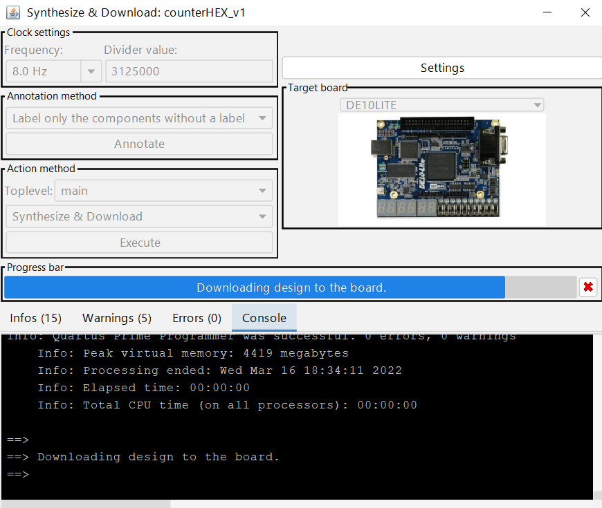
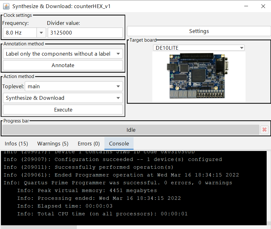
If the board is connected to your computer, and you don't have errors in your schematic, you should see your design working on the board.