FPAA Starter Board
FPAA Starter Board
(Version 1.0)
Introduction
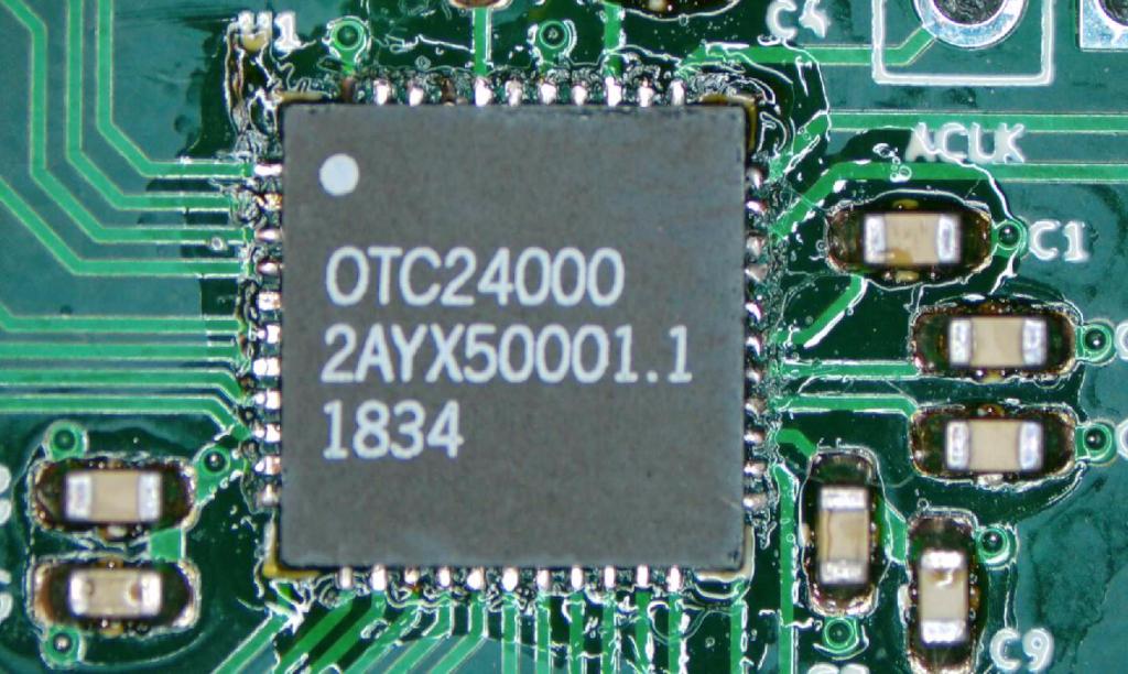
The goal with this PCB board is to test the FPAA chip OTC24000 from Okika Technologies with different microprocessors to dynamically reconfigure the analog matrix.
Briefly, the OTC24000 "is an “Analog Signal Processor”; ideally suited to signal conditioning, filtering, gain, rectification, summing, subtracting, multiplying, etc. The device also accommodates nonlinear functions such as sensor response linearization and arbitrary waveform synthesis".
Reference Designs
As reference designs, we used the OTC24000 Datasheet Rev1.0 (PDF) and the schematics from the DynAMx Development Kit (PDF).
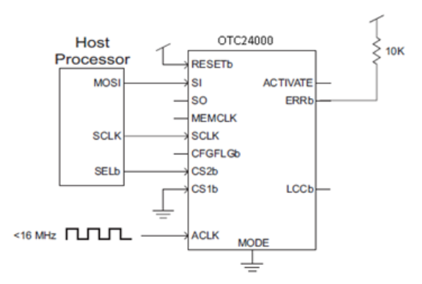
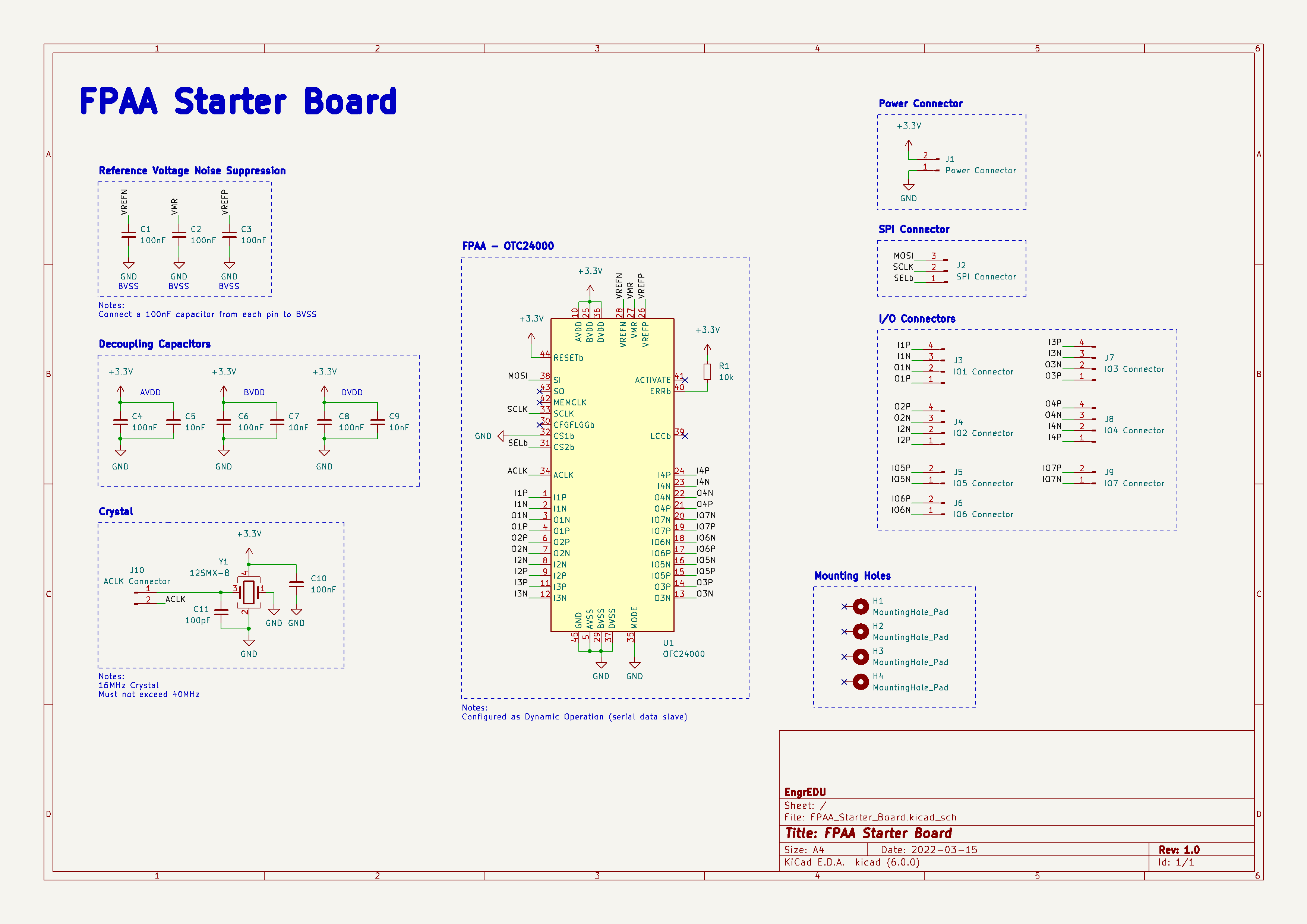
For this first version, we connected the OTC24000 in dynamic operation, which involves configuring the FPAA as a serial data slave. In this configuration, we can send configuration data to the FPAA using SPI compatible signaling.
Note: we will create a second version of this board that allows chaining FPAAs together. For now, you can only use one FPAA with this design.
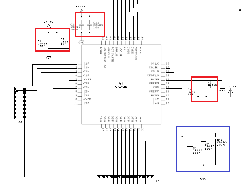
We added the decoupling capacitors (in red) and the reference voltage noise suppression capacitors (in blue).
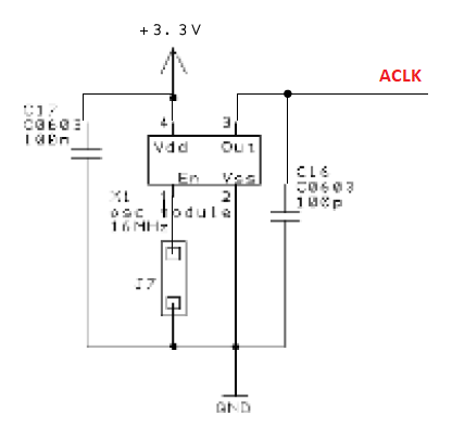
For the analog clock (ACLK) pin, the FPAA can receive this clock from a square wave generated by a microcontroller or a crystal. The clock frequency should not exceed 40 MHz.
PCB Design Stage
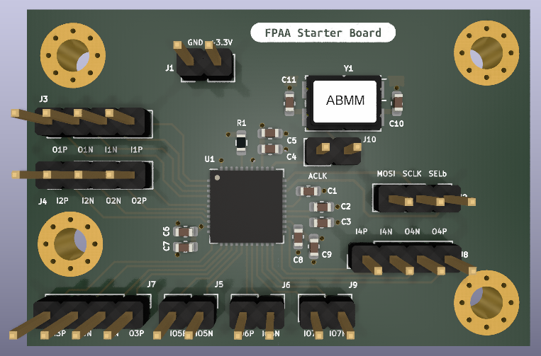
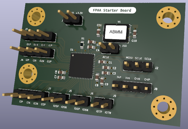
3D Model
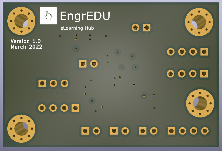
During design stage, Fusion 360 and KiCad were used to model the board and get an idea on how the board would look like.
Inputs & Outputs
- x2 Type 1 analog input / output
- x2 Type 1a analog input / output
- x2 Type 2 analog input / output
- x1 Type 2a analog input / output
PCB
Schematics
Interactive HTML BOM
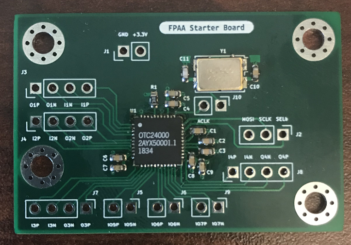
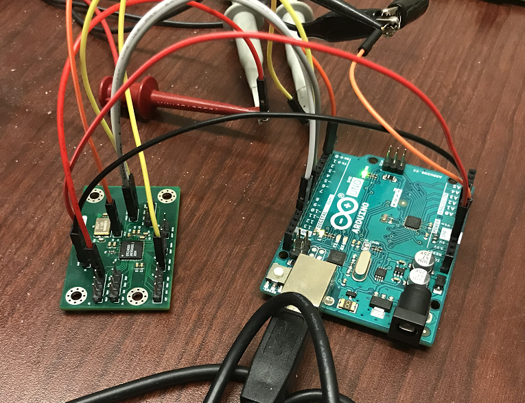
Assemble Stage
Coding Stage
We will be using two different platforms to program the OTC24000: a Raspberry Pi and an Arduino Uno. You can repeat the process described in this section for any microcontroller as long as you have access to an SPI communication and potentially a way to produce a output square waveform (with low jitter) up to 40MHz.
Note: If you don't have a way to produce a square wave, you need to add a crystal to your design.
The FPAA Starter Board PCB has the ability to connect or disconnect an on board crystal so you can test the OTC24000 with your preferred microcontroller and adjust your PCB design accordingly.
SPI Parameters
In systems using Okika Technologies devices, the master is always the host processor. Okika Technologies devices are always SPI slaves. The OTC24000 supports the following SPI parameters (Link):
- Mode 0 and 3
- MSB always sent first
- 8 bits per word
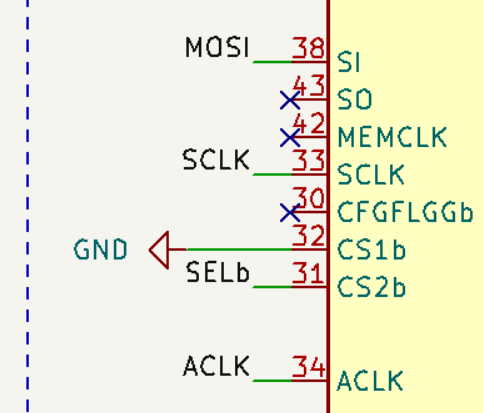
All you need to connect is 3 SPI pins, MOSI, SCLK and SELb (or chip select).
DynAMx Design Lab Software
You need to use the DynAMx Design Lab Software to create your filters/design and generate the configuration file that will be deployed on the FPAA.
Let's go over an example and design a low pass filter using the DLFiltertool.
Step 1: Set Chip Clock
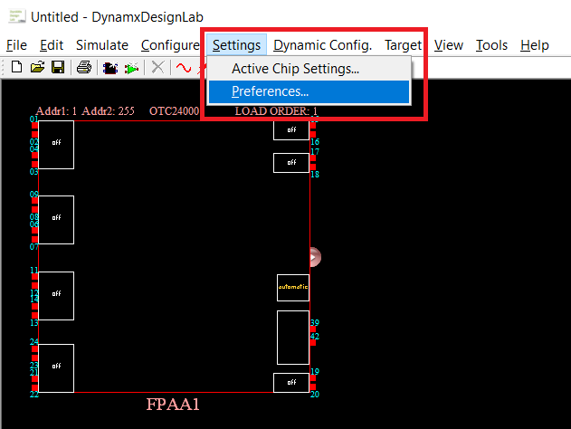
Set the Master Clock Frequency of your project. Go to Settings -> Preferences
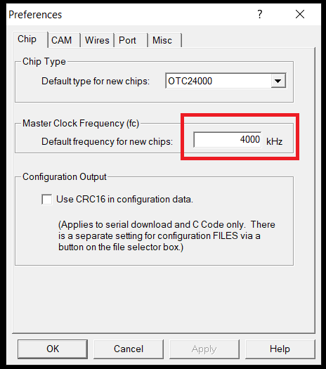
Set the Master Clock Frequency to the same frequency as your ACLK. For example, for the Arduino example ACLK = 4 MHz, for the Pi example ACLK = 16 MHz, and for Okika Development Kit ACLK = 16 MHz.
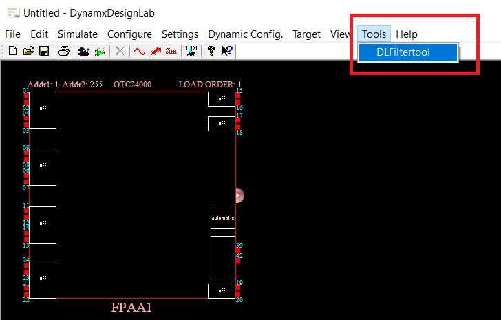
Step 2:
Go to Tools -> DLFiltertool
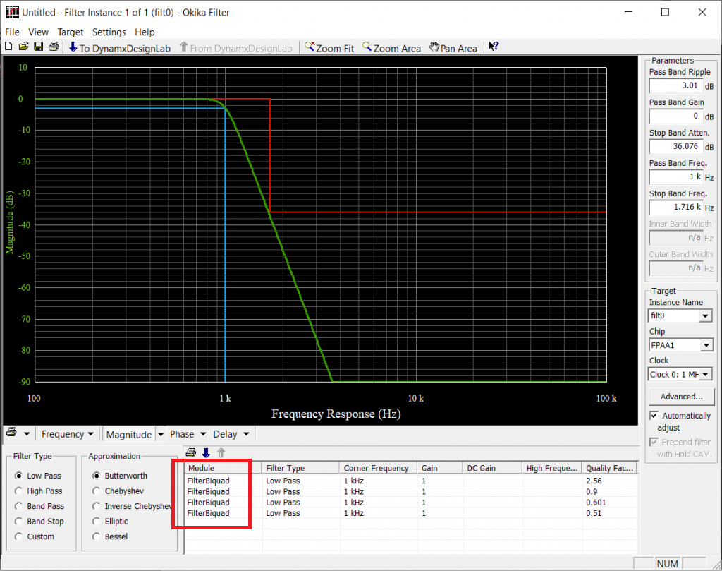
Step 3: Low Pass Filter Design
Design a low pass filter with the specs of your choice.
Note: Because we only have one FPAA, make sure that you don't exceed more than 4 filters under Module.
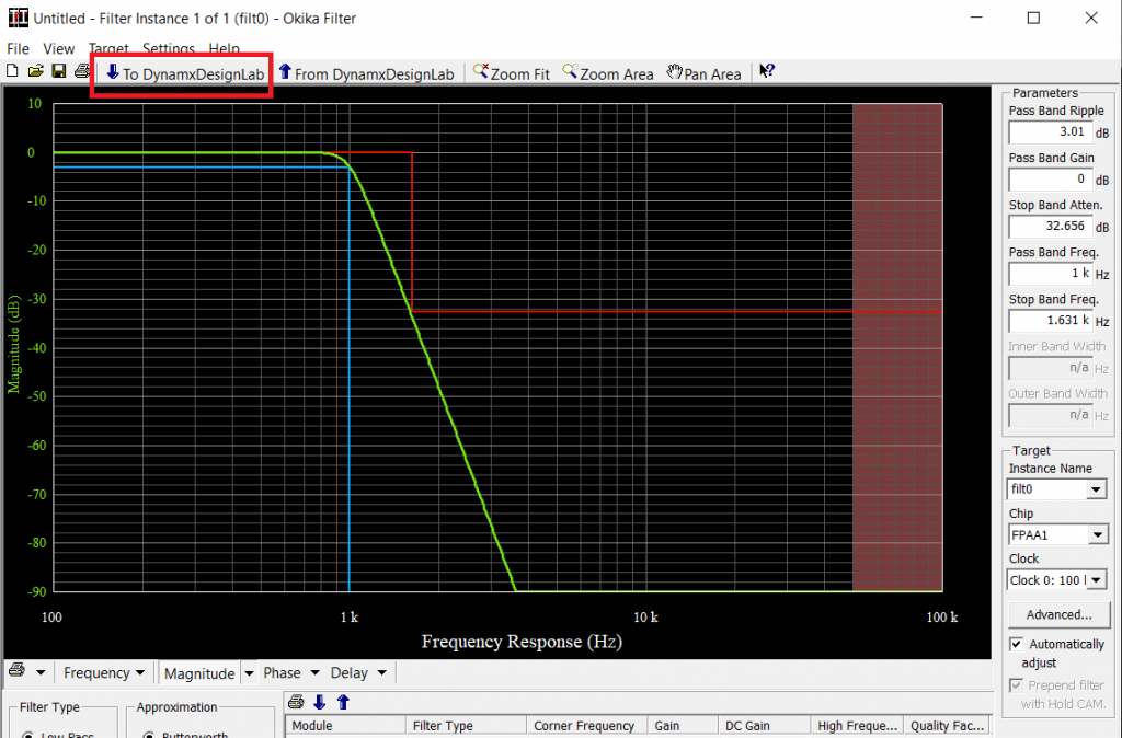
Press "To DynamxDesignLab" button to deploy the filter design onto the FPAA chip working area.
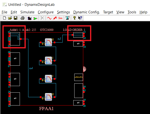
Step 4: Assign Input and Output Pins
If you expand the resources panel, you will see that this design is using all available op amps on the FPAA.
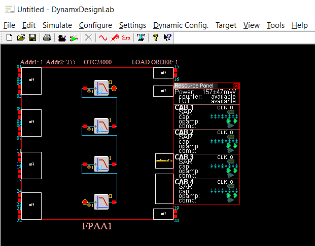
Next, create a input pin and output pin. Route the pins to the respective filter input and output pinouts.
Step 5: Generate Configuration File
Last step is to generate a configuration file (ahf file). Go to Configure -> Write Configuration Data to a File...
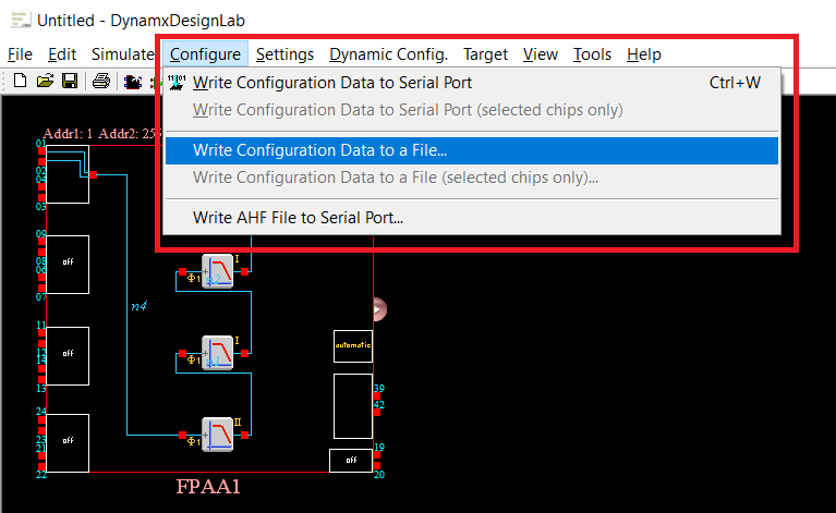
Give a name of your choice and remember where you saved this file.

DynAMx Project for Pi (16MHz) (Link) and ahf File (Link)
DynAMx Project for Arduino Uno (4MHz) (Link)
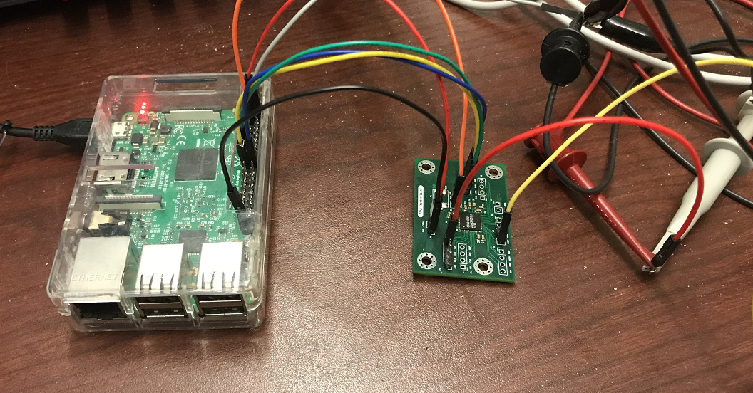
Raspberry Pi
On the Raspberry Pi side, we will create a program that reads the configuration file (ahf file) generated by DynAMx and sends all that information to the FPAA using SPI.
Enable SPI Interface
You should have the SPI interface enabled in your Raspberry Pi.
Note: If you don't know how to set that up, you can follow this Sparkfun tutorial.
SPI Python Packages
For simplicity, we will be using python to interface with the SPI pins. There are several python packages that can be used to interact with the SPI pins. This section covers two of them: spidev and pigpio.
spidev comes installed by default and after you enable the SPI interface you should be able to use it right away in your code. spidev is enough to program the FPAA however, if you want to generate the clock to the ACLK with the Pi, you need to use the pigpio package to access the Pi PLL and route the GPCLK to the Pi output pins. pigpio also offers the ability to control the SPI pins.
- Option 1: write the code with pigpio to generate the ACLK and use spidev to read the configuration file and send the data over SPI to the FPAA
- Option 2: use pigpio for everything; to generate the ACLK and read the configuration file and send the data over SPI to the FPAA.
I will leave the code below for both options.
Python Code
Option 1
import pigpio
import spidev
from time import sleep

# GPIO CLOCK PINs
GPIO_4 = 4

pi = pigpio.pi()
if not pi.connected:
    exit()

# Set FPAA Clock
pi.hardware_clock(GPIO_4, 16000000) # 16 Mhz

# Open FPAA ahf File
file_ahf = open('LP_Test_16MHz.ahf', 'r')

# Convert to list of int's
ahf = []
ahf_raw = ['']
ahf_raw = file_ahf.readlines()
for loop in range(0, len(ahf_raw)):
    temp_bytes = ahf_raw[loop]
    ahf.append(int(temp_bytes[0:2], 16))

file_ahf.close()

# print(list(ahf)) #DEBUG

# Enable SPI
spi = spidev.SpiDev()

# Open a connection to a specific bus and device (chip select pin)
BUS = 0
DEVICE = 0
spi.open(BUS, DEVICE)

# Set SPI speed and mode
spi.max_speed_hz = 15600000 #15.6 MHz
spi.mode = 0b11
spi.lsbfirst = False
spi.bits_per_word = 8

sleep(0.01) # Not necessary

# Soft Reset the FPAA
reset_config = [0,0,0,0,0,213,1,111,0]
response = spi.xfer2(list(reset_config))

# Load Configuration
response = spi.xfer2(list(ahf))
#print(response) #DEBUG

spi.close()
GitHub Code (Link)
Option 2
import pigpio
from time import sleep

# GPIO CLOCK PINs
GPIO_4 = 4

pi = pigpio.pi()
if not pi.connected:
    exit()

# Set FPAA Clock
pi.hardware_clock(GPIO_4, 16000000)

# Open FPAA ahf File
file_ahf = open('LP_Test_16MHz.ahf', 'r')

# Convert to list of int's
ahf = []
ahf_raw = ['']
ahf_raw = file_ahf.readlines()

for loop in range(0, len(ahf_raw)):
    temp_bytes = ahf_raw[loop]
    ahf.append(int(temp_bytes[0:2], 16))

file_ahf.close()

#print(list(ahf)) # DEBUG

# Open SPI
SPI_MAX_SPEED = 1000000
SPI_MODE = 3
h = pi.spi_open(0, SPI_MAX_SPEED, SPI_MODE)

# Soft Reset the FPAA
reset_config = [0,0,0,0,0,213,1,111,0]
pi.spi_write(h, list(reset_config))

# Load Configuration
pi.spi_write(h, list(ahf))

pi.spi_close(h)
GitHub Code (Link)
Soft Reset
At power-on-reset, the FPAA clears its memory, placing the device in a benign condition. Once this power-on-reset sequence concludes, the device is ready to accept configuration data. The first configuration data set loaded into the device after a reset is called a Primary Configuration.
OTC24000 devices may be reconfigured (without intervening resets) using the Update format described later under Dynamic Reconfiguration.
However, to upload a new configuration data, we need to perform a soft reset before sending the configuration data again to the FPAA.
If you use a different platform to send the configuration data to the FPAA don't forget to add and send the soft reset data sequence first.
reset_config = [0,0,0,0,0,213,1,111,0]Arduino Uno
On the Arduino side, we will create a program that sends the configuration file (ahf file) content generated by DynAMx to the FPAA using SPI.
Generate a Configuration .h File
It is not possible to read files from Arduino. With that in mind, we need to save the contents of the ahf file into an array of bytes. DynAMx software can do that for us.
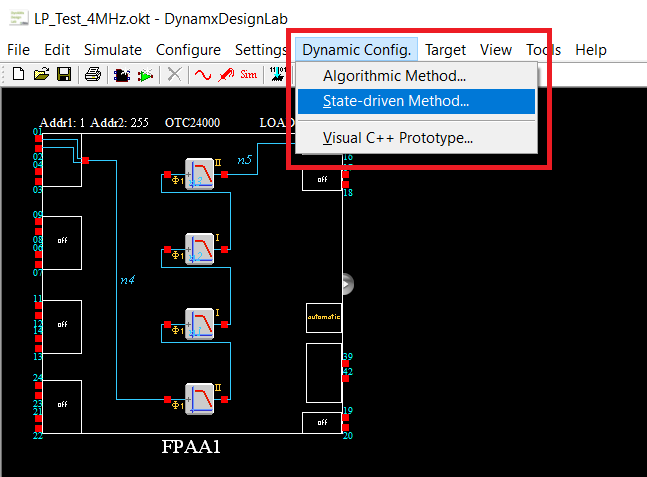
Step 1:
Under you project, go to Dynamic Config -> State-driven Method.
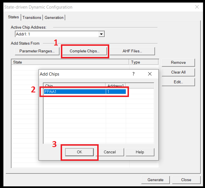
Step 2:
Press the "Complete Chips" button, select your FPAA1 chip and press "Ok".
Steps 3:
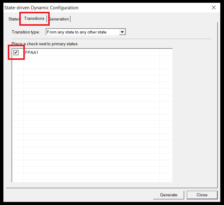
Go to the "Transitions" tab and check the FPAA1.
Step 4:
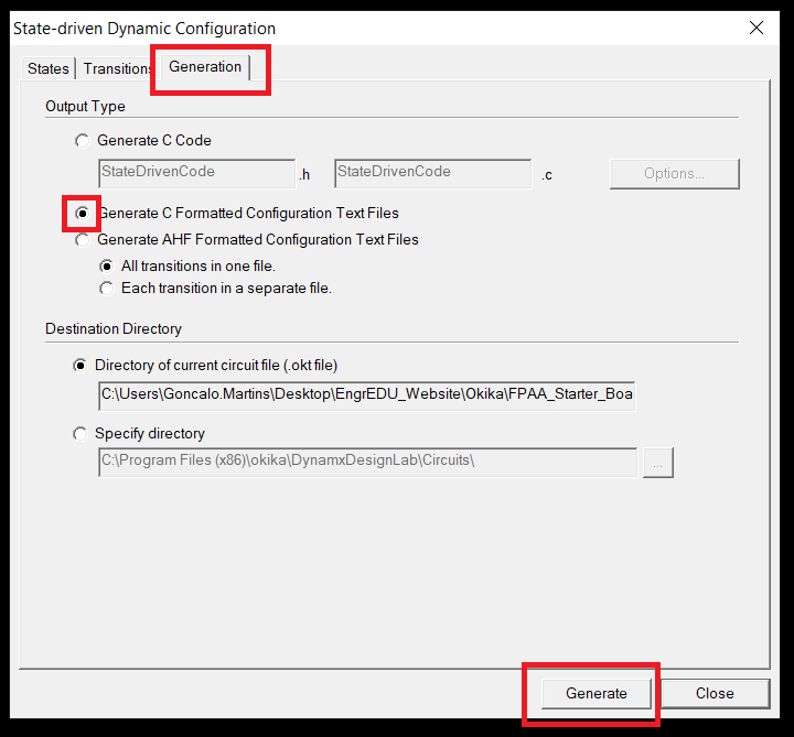
Go to the "Generation" tab, check "Generate C Formatted Configuration Text files" and press the "Generate" button. DynAMx will generate the ahf file into an array of bytes formatted in C (the generated file has a txt extension).
Step 5:
We are almost there. The last step requires to change the extension of the file from txt to .h file (change the name of the file too, to a more descriptive name) and add a type and name for the data. In this case we want an array of bytes and write whatever name makes sense for you to use in your application (in this case we called it data).
const byte data[] =
{
0x00, 0x00, 0x00, 0x00, 0x00, 0xD5, 0xB7, 0x20,
0x01, 0x00, 0x01, 0xC1, 0xC4, 0x00, 0x0E, 0x20,
...
Don't forget to close the parenthesis at the end of the data...
...
0x2A, 0x00
};
Arduino Code
We called the file generated by DynAMx on the previous step LP_Test_4MHz.h
Create an Arduino Uno project and add the following code to it:
#include <SPI.h>
#include "LP_Test_4MHz.h"

#define SELb 10
#define ACLK 3

void resetConfig(){
  // State Reconfiguration
  byte msg[9] = {0, 0, 0, 0, 0, 213, 1, 111, 0};

  digitalWrite(SELb, HIGH);
  for(int i=0; i<9; i++){
    SPI.transfer(msg[i]);
  }
  digitalWrite(SELb, LOW);
}

void sendConfig(){
  // Send Configuration
  digitalWrite(SELb, HIGH);
  /* sizeof is six greater than the size given at the top of the
   *  text file. This is because six dummy bytes have been added to
   *  the data, five at the start and one at the end.
   *  */
  for(int i=0; i<(sizeof(data)+6); i++){
    SPI.transfer(data[i]);
  }
  digitalWrite(SELb, LOW);
}

void setup() {
  // Initialize ACLK
  pinMode(ACLK, OUTPUT);
  TCCR2A = 0x23;
  TCCR2B = 0x09;
  OCR2A = 3;
  OCR2B = 1;

  // Initialize SPI
  pinMode(SELb, OUTPUT); // set the SS pin as an output

  SPI.begin();
  SPI.setBitOrder(MSBFIRST);
  SPI.setDataMode(SPI_MODE3);
  SPI.setClockDivider(SPI_CLOCK_DIV2);

  resetConfig();
  sendConfig();
}

void loop() {
}
ACLK @ 4MHz
The code presented on the previous section, is generating a clock for the FPAA ACLK at 4 MHz on digital pin 3.
We are also sending the soft reset configuration data sequence first before sending the configuration data stored on the LP_Test_4MHz.h file.
Testing Stage
In this section we will be comparing the simulator under DynAMx with real measurements from an oscilloscope.
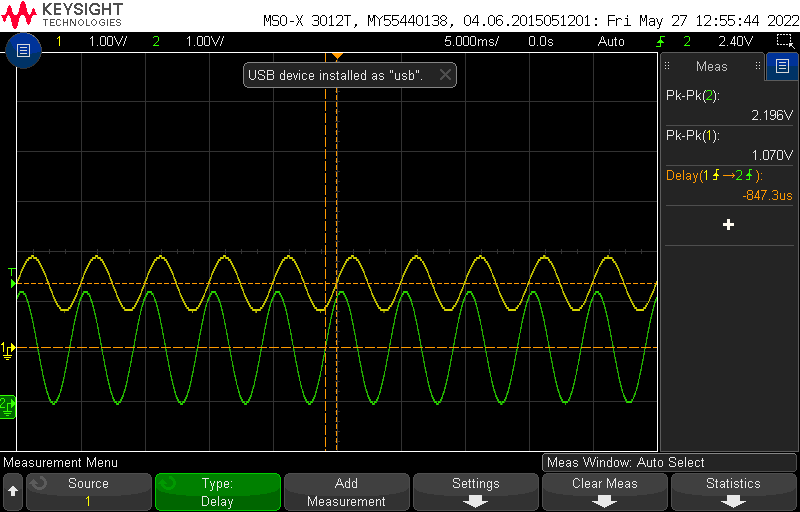
Raspberry Pi

200 Hz
Simulator
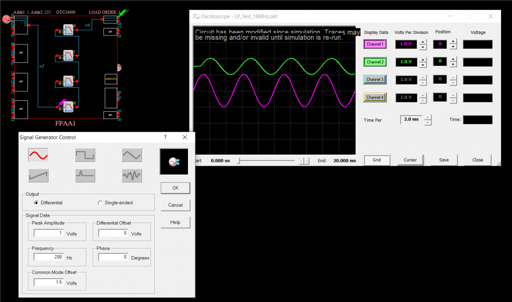
Oscilloscope
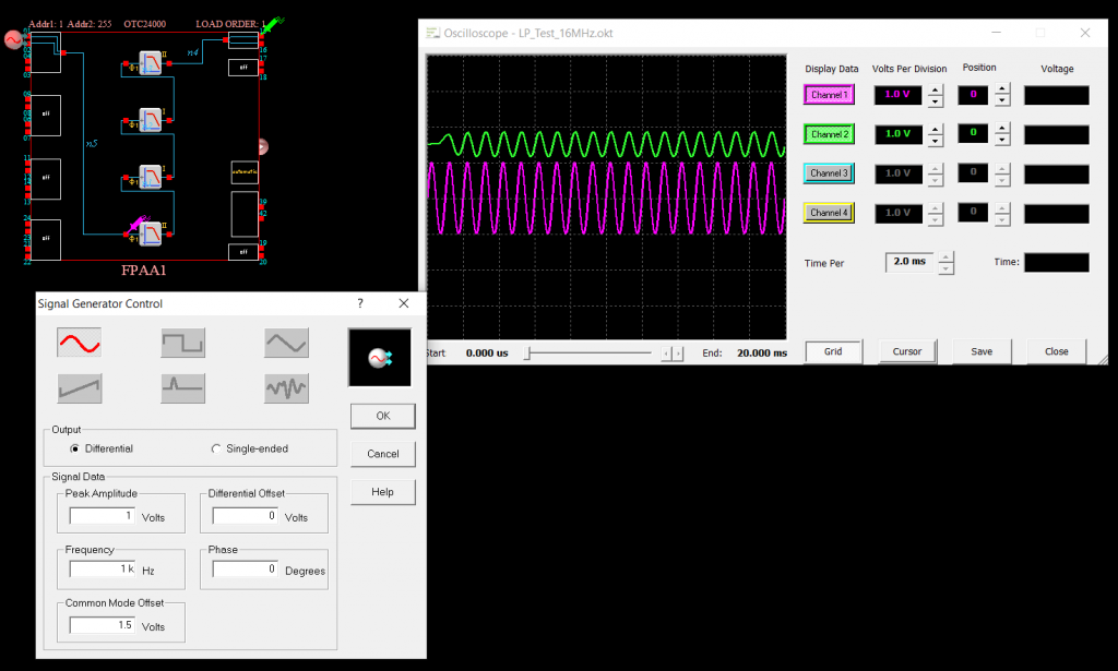
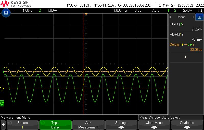
1 KHz
Simulator
Oscilloscope
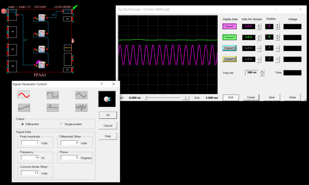
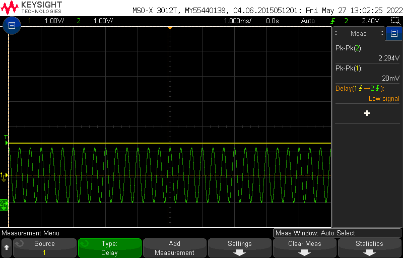
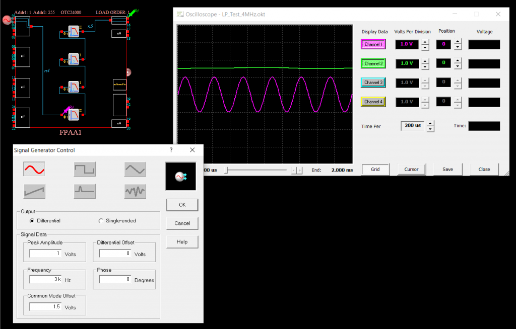
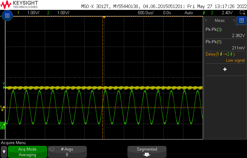
3 KHz
Simulator
Oscilloscope
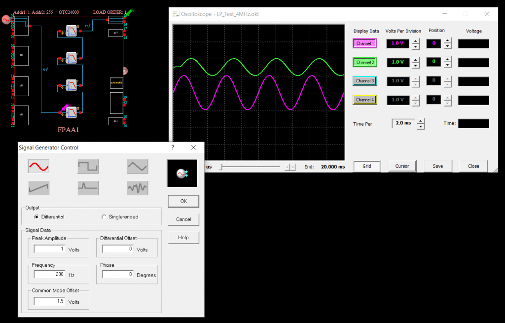
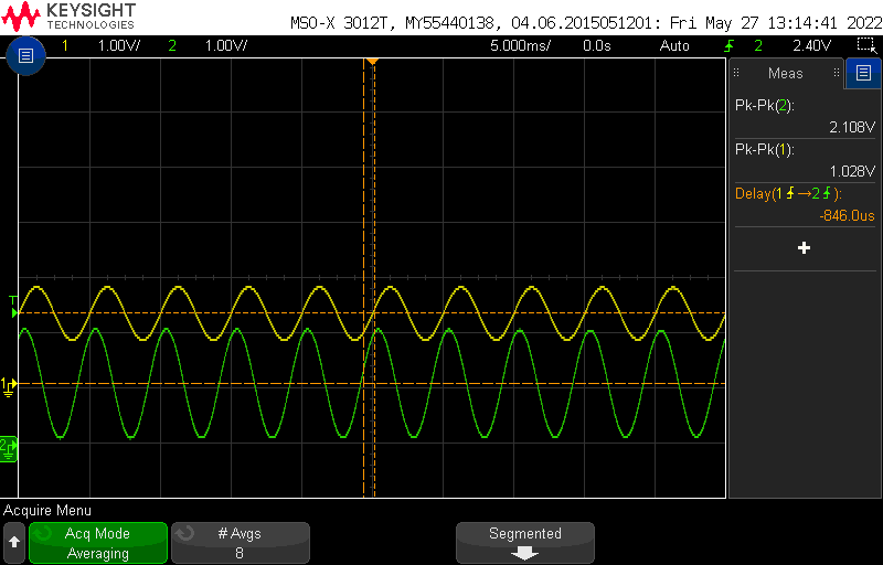
Arduino Uno
200 Hz
Simulator
Oscilloscope
1 KHz
Simulator
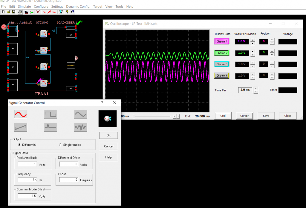
Oscilloscope

3 KHz
Simulator
Oscilloscope
Dynamic Reconfiguration
Performance Stage
Test 1
Soon...