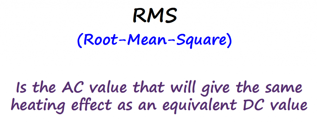
Root-Mean-Square (RMS)
You probably already encounter words like 


Motivation
DC Circuit
Let's consider the following DC circuit: a 5V dc power supply connected to a 100Ω resistor. Applying ohm's law the current that flows in the circuit is 
The power dissipated by the resistor is also trivial to find out: 
If you look at the plot of the resistor's current (yellow line) and voltage (green line), with no surprise, we see a constant voltage and constant current over time.
In DC, the concept of average voltage and instantaneous voltage is the same. Notice that if you take the average voltage over time (which is equal to 5V) is going to be equal to picking a random point and measure the voltage at that specific point in time (5V).

AC Circuit
Let's now consider the same circuit, but let's substitute the DC voltage source with an AC voltage source (sinusoidal waveform). I am going to make a claim and state that this AC circuit is equivalent to the DC circuit. We will understand this claim later, for now let's go with this.
Note: I adjusted the
to 7.07V instead of 5V on purpose. This is to make sure that when we go over the math on the sections below we can understand the results and related the circuits accordingly. For now, just accept the 7.07V, things will make sense at the end.

What is the power dissipated by the resistor now? Which value of voltage and current are we going to choose to calculate the power?
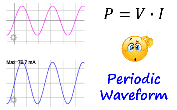
One thing that we know for sure is that the concept of average and instantaneous (voltage, current or power) is not the same for an AC circuit.

Instantaneous values can easily be taken at any instance of time but how do we calculate the average value of a periodic waveform in a way that is meaningful for circuit analysis?
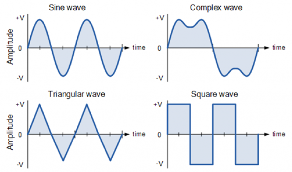
Periodic Waveforms
There are different types of periodic waveforms and the main idea described in this article. applies to any periodic waveform. However, we will be focusing on the sinusoidal waveform because that is the one most common in circuits.
Average Value (Full Cycle)
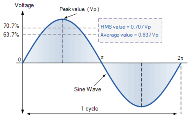
Let's start by exploring the average value for a full cycle.
Consider 
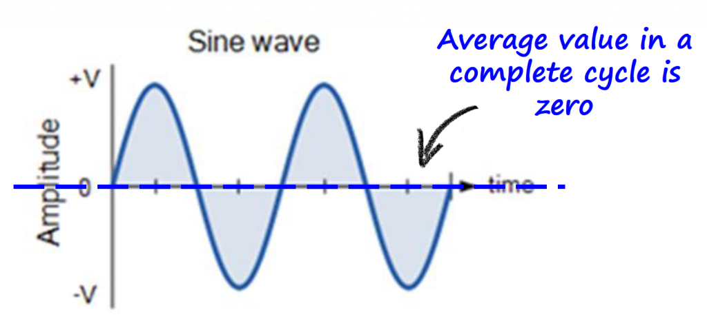
Mathematically we can calculate the average value for a full cycle using the following formula: 
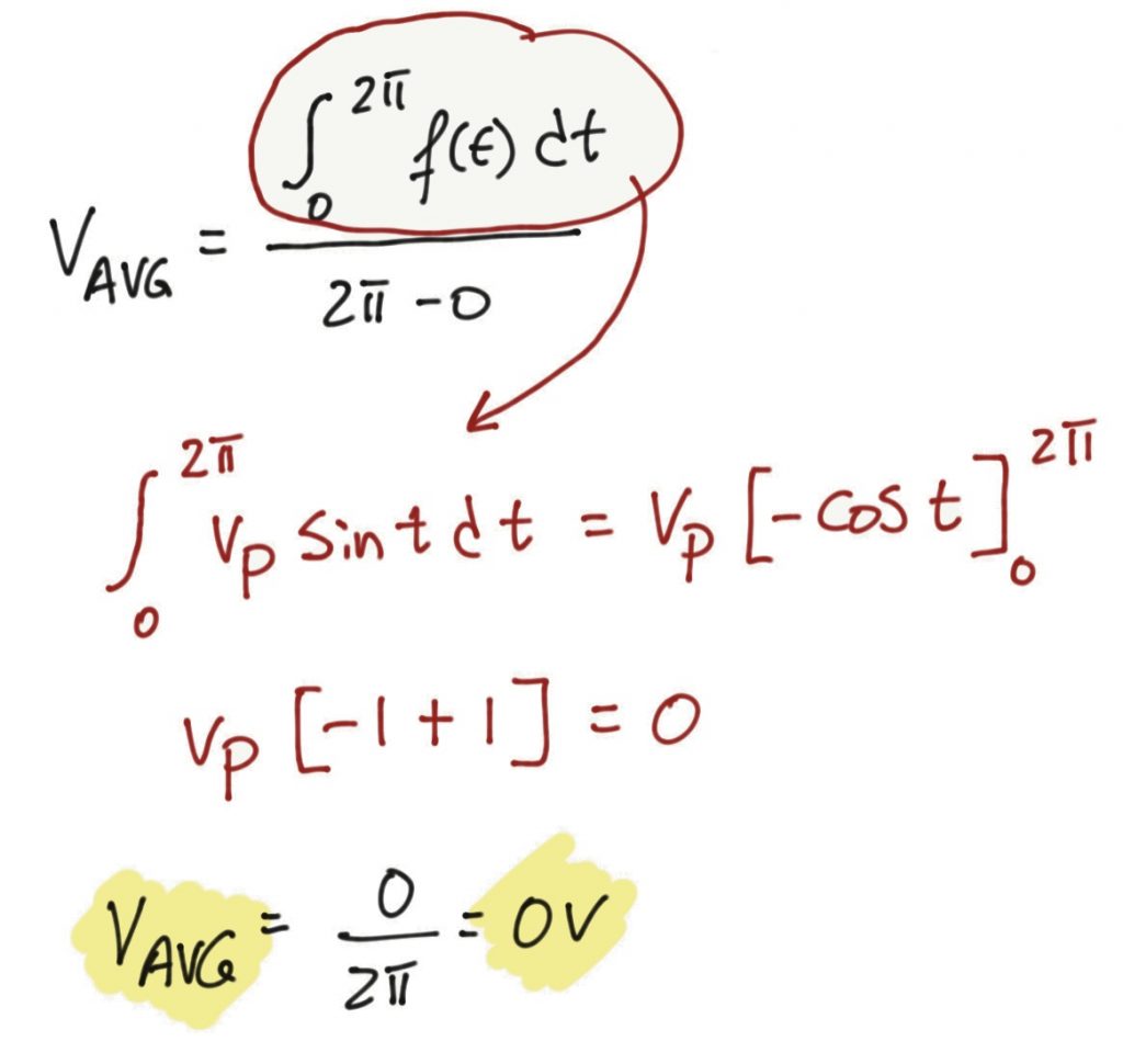
The average value in this form is not that useful. We need to find a different way to calculate the average value for periodic signals.
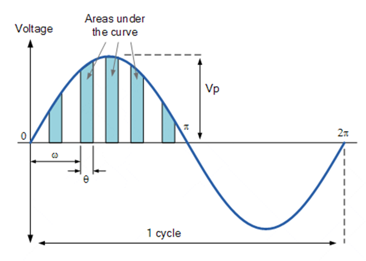
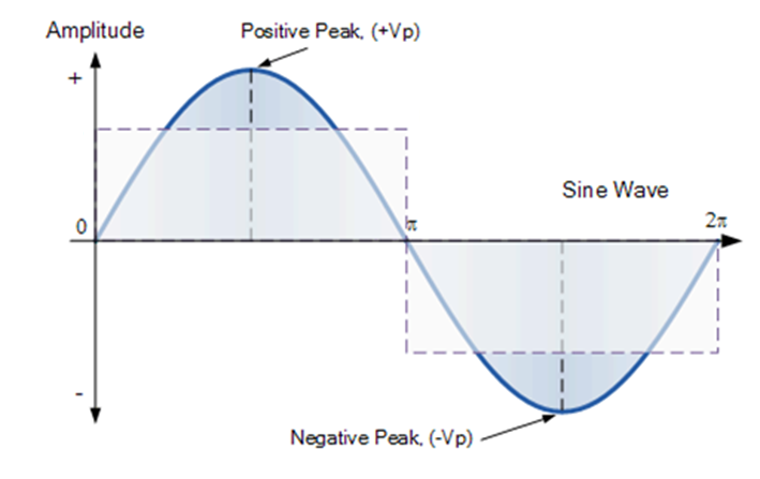
Average Value (Half Cycle)
Since the positive part of a sinusoidal waveform is equal to the negative part, let's focus on calculating the average value of half a cycle using the same formula as in the previous section but changing the limits of integration accordingly.

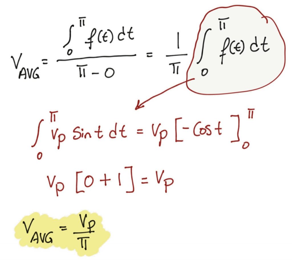
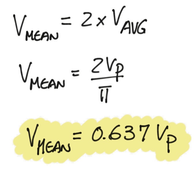
Let's include the other half cycle by multiplying the result by 2.
Note: I am calling it
so we can distinguish it from, but in this context means the same thing.

AC Power Calculations
Let's try to use the 
Measured values from Falstad simulation (Link):


The average voltage is 


In the motivation section, I made a claim and stated that the AC circuit and the DC circuit where equivalent. For that to be true, the power dissipated by the resistor needs to be the same for both circuits.
It is clear that using the average value (half a cycle) to calculate the power is not giving the same result (
We need to approach this problem differently.
Different Approach
Instead of calculating the average value (half a cycle) of voltage and current and plug those values into 


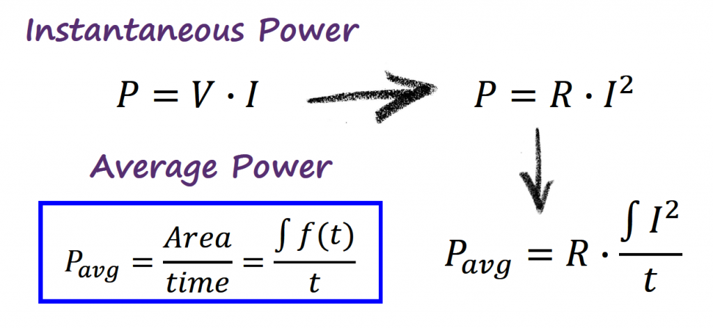
Note: we can also work with
, which will give. The idea is the same and will give the same answer.

The question that now rises is, what is this new expression 

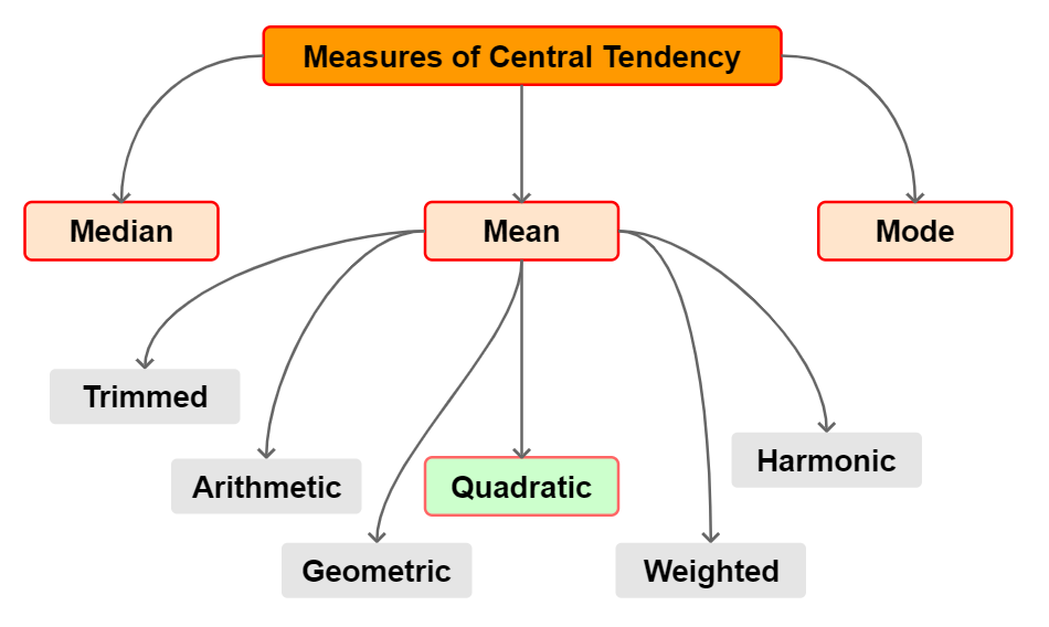
Measures of Central Tendency
In statistics there are different types of averages also called measures of central tendency. The most common types of averages are the mean, median and mode. However, inside the mean category, there are more options available.
It is outside of the scope of this article to cover statistics. If you want to read more about this subject you can check [REF2] [REF3] [REF4].
Equations (discrete form) for the different types of mean:
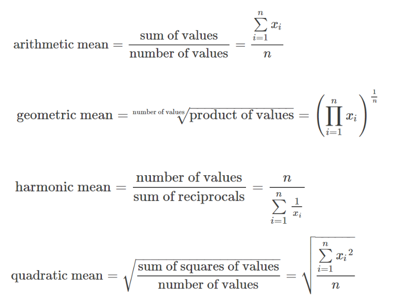
A particular interest relation to pay attention to, is between the arithmetic and the quadratic mean. Notice that the quadratic mean squares all the numbers, then takes the usual average, and then takes the square root.
Since we tried the arithmetic mean during the average power (half cycle), it would be interesting to explore if there is a way to apply the quadratic mean and see the results that we get. The cool part about this is that without too much effort the quadratic mean is already present in our new expression of the average power. Let's see how...
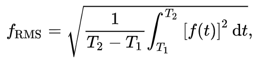
The continuous form representation of the quadratic mean is:
Relating the quadratic mean with the new average power equation, 
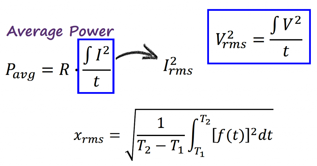
In fact, the quadratic mean is also called root-mean-square (RMS).
Root-Mean-Square (RMS)
We have a new expression for the average power: 
With this new finding, let's calculate the average power using the 
AC Power Calculations
Let's now use this
The measured values from Falstad simulation are the same (Link):
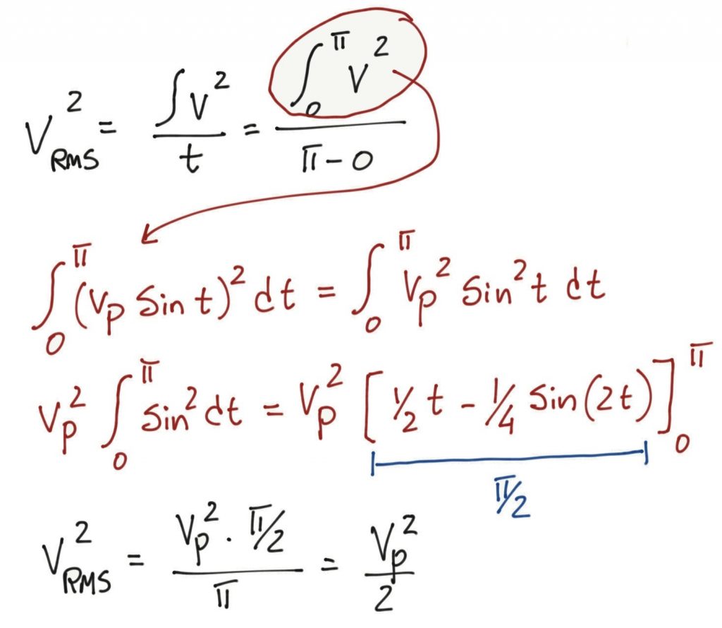
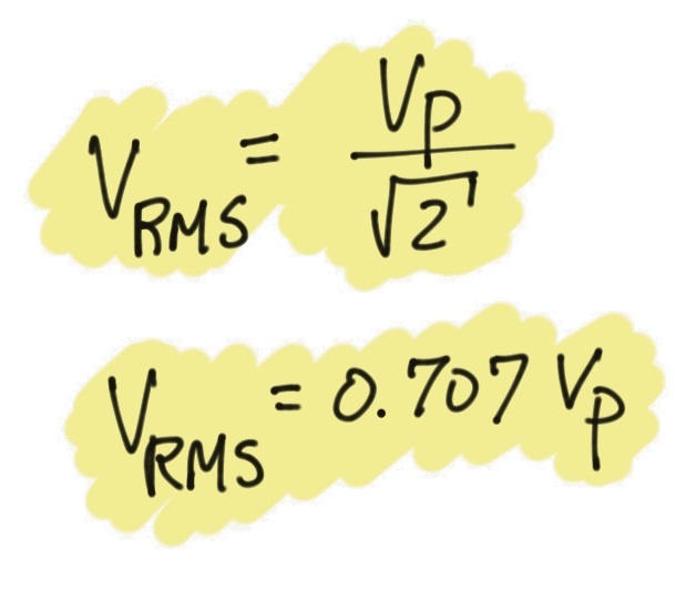
The RMS voltage is 

We can apply the same process using the RMS current, 

It is clear that using the RMS values to calculate the power gives the same result (
Summary
If we go back to the AC circuit from the motivation section, we can fix the measurement tools (voltmeter and ammeter) to reflect the RMS value of the circuit.
We are also in better shape now to understand why at the beginning I fixed the maximum voltage from 5V to 7.07V. If we simulate the circuit with a maximum voltage of 5V we don't get the equivalent AC circuit. We need to raise the maximum voltage of the AC voltage source to get the equivalent DC heating effect in the resistor.
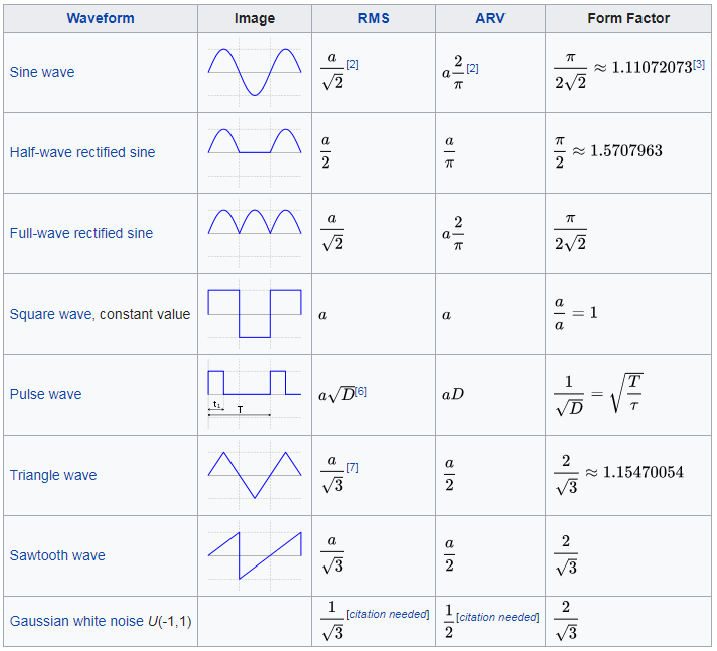
Average vs RMS and Form Factor
Despite the fact that the average value (half a cycle) of an AC circuit doesn't correlate with the DC circuit at first glance, it is still an important parameter to calculate.
The relationship between the average value and the RMS value is called form factor: 
Why is form factor important?
AC measuring instruments are often built with specific waveforms in mind. For example, many multimeters on their AC ranges are specifically scaled to display the RMS value of a sine wave. Since the RMS calculation can be difficult to achieve digitally, the absolute average is calculate instead and the result is multiplied by the form factor of a sinusoid.
You are probably already guessing that if the sinusoidal waveform is not pure, using the average and the form factor to get the RMS is not going to be accurate.
This dictates the difference between when to use regular multimeters or true RMS multimeters. Topic for another article.
References
- [REF1] "RMS Voltage Tutorial", Electronics Tutorials [Article]
- [REF2] "Mean, Median, and Mode: How Visualizations Help Find What’s "Typical"", The Stats Ninja Website [Article]
- [REF3] "Visualizing the Geometric and Harmonic Means", Medium [Article]
- [REF4] "Four Kinds of “Mean”", The Math Doctors [Article]