IMU as a Musical Instrument
Inertial Measurement Unit (IMU) as a Musical Instrument
Vertical Movement III: AI Musical Improvisation with Sensors
Musical Improvisation (Demo)
- Demonstration of generative electronic music under control of an IMU
System Block Diagram
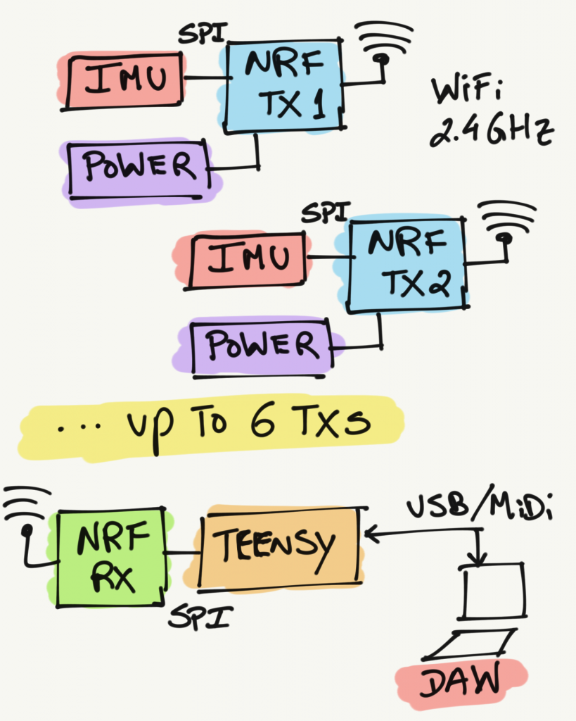
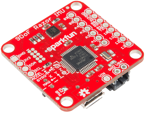
- IMU: SparkFun 9DoF Razor IMU M0
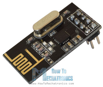
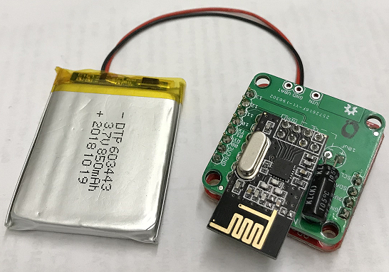
- Radio: NRF24L01 transceiver module
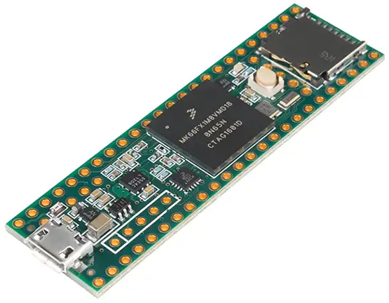
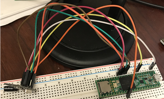
- Microprocessor: Teensy 3.6
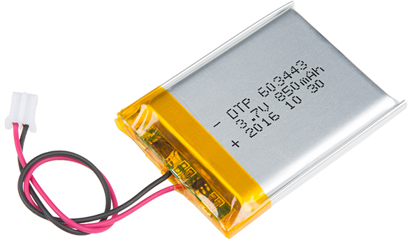
- Power: Lithium Ion Battery - 850mAh
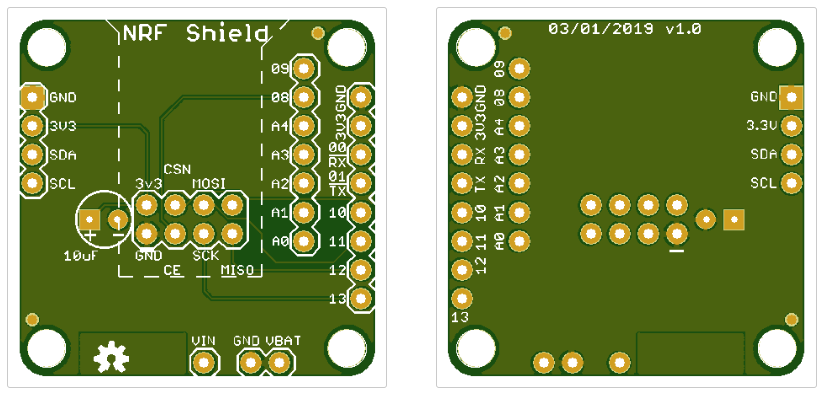
- PCB Board 1: Razor NRF Shield version 1.0 (Eagle + Gerber Files)
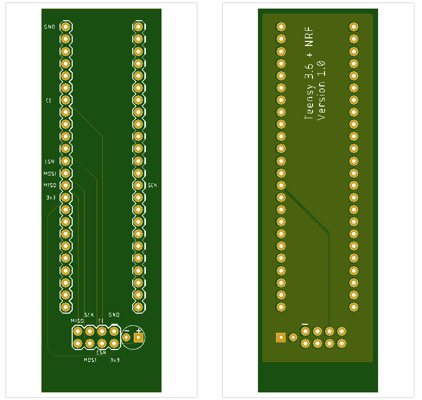
- PCB Board 2: Receiver Board version 1.0 (Eagle + Gerber Files)
Bill of Materials (BOM)
| Name | Quantity | Unit Price | Link |
| IMU Razor | 1 | $35.95 | Sparkfun |
| Radio NRF24L | 10 | $11.98 | Amazon |
| Capacitor | 2 | $0.45 | Sparkfun |
| Teensy 3.6 | 1 | $33.25 | PJRC |
| Lipo Battery | 1 | $9.95 | Sparkfun |
How to Put the System Together
-> Step 1: Acquire the components- Buy the components provided on the BOM section.
- Download the Gerber Files for the two PCB boards.
- Order the PCB Boards.
- The downloaded zip file is ready to be sent to a manufacture house. If you don't have any idea what I am talking about you can order your board from Seeed Studio or JPLPCB or OshPark or WellPCB
- You just need to provide the zip file to the respective website. No need to modify any of the pre defined specs.
- You can change the quantity to any number of units that you want to manufacture
- Once you get the components (it can take from 1 to 3 weeks depending from where your order them) lets put them together.
- Transmitter Module:
- Solder the NRF24L01 transceiver module on PCB Board 1.
- Solder the capacitor on PCB Board 1.
- Solder the Razor IMU on PCB Board 1.
- Connect the Lipo battery.
- Receiver Module:
- Solder the NRF24L01 transceiver module on PCB Board 2.
- Solder Teensy on PCB Board 2.
- Solder the capacitor on PCB Board 2.
First lets take care of the Transmitter Module.
- Follow the directions for the 9DoF Razor IMU M0 Hookup Guide
- Running the demo provided by default will make sure that the IMU is working properly.
- The radio will not be working right away. We will need to change some things around.
- Let's take care of the radio
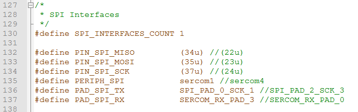
- NRF24L01 works over SPI. By default the Razor SPI is connected to the uSD Card. All we need to do is to redirect the SPI pins to the expansion pin breakouts where the radio is connected.
- Find the original library code for the SAMD21 board variant.h
Possible path on windows machines "..\AppData\Local\Arduino15\packages\SparkFun\hardware\samd\1.5.4\variants\SparkFun_9DoF_M0" - Find the place where the SPI Interface #defines are declared and change the following lines of code:
- Download the IMU_NRF_TX.zip example, compile and upload it to your module.
- Connect the Teensy 3.6 to your PC and allow any drivers to be installed.
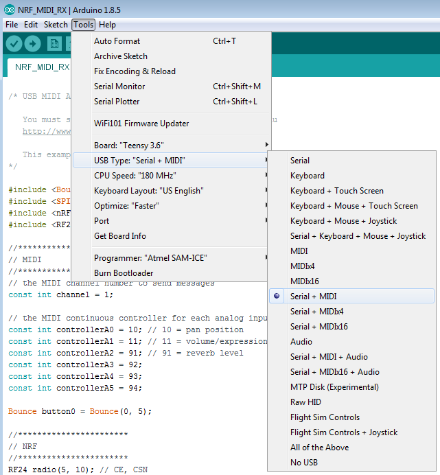
- Open a new instance of the Arduino Development Environment (this is an important step). The Razor Module and the Teensy Module use different boards and in order to have both working at the same time you need to have the projects open separately. Do not use open to open the Teensy Project, it will not work.
- Download the NRF_MIDI_RX.zip example.
- Before uploading any code to the Teensy board make sure that you change the USB Type to serial + midi
- Compile and upload the code to the board.
- Open the serial port and you should be able to get data from the Transmitter Module.
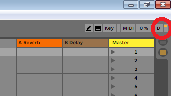
- If you open ableton you should be able to start receiving MIDI messages right away. As you move the Transmitter module you will see on the top right corner a yellow light blinking as you move the module around
- It is probably a good idea to understand how MIDI works under the Teensy board so you can change your code accordingly to your needs.