Circuits 2
Main Reference Book
Reference Material
Charles Alexander, and Matthew Sadiku
“Fundamentals of Electric Circuits”, 7th Edition, McGraw-Hill, 2017
(Prior or more recent versions of this book are also acceptable)
(5th Edition Free Link)
(Spanish Version Link)
Tim Hanshaw
“Real Analog: An Introduction to Electrical Circuits”
(Free Link)
Roland E. Thomas, Albert J. Rosa, and Gregory J. Toussaint
“The Analysis and Design of Linear Circuits”, Wiley, 7th Edition, 2012
(Prior or more recent versions of this book are also acceptable)
Course Goals
- AC analysis of linear circuits to include circuit theorems via classical and transform techniques.
- Emphasis is placed on the Laplace transform, including use of pole-zero and Bode diagrams to analyze and design circuits, including multiple filters (single pole cascade, Butterworth, Chebychev), and step response circuits.
- Phasor applications to sinusoidal steady state analysis and AC power.
- Computer analysis software is used as an aid to circuit analysis.
- Laboratory program practicing time and frequency domain analysis and design techniques on step response and filter problems.
- Applications to instrumentation and circuits.
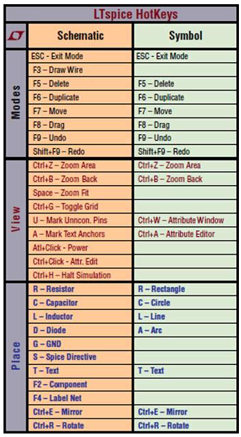
Software
LTSpice
Course Modules
Module 0 – Energy Storage Elements (Review)
- Qualitatively state the effect of energy storage on the type of mathematics governing a system
- Define transient response
- Define steady-state response
- Write the mathematical expression for a unit step function
- Sketch the unit step function
- Sketch shifted and scaled versions of the unit step function
- Write the mathematical expression for a decaying exponential function
- Define the time constant of an exponential function
- Sketch a decaying exponential function, given the function’s initial value and time constant
- Use a unit step function to restrict an exponential function to times greater than zero
- Write the circuit symbol for a capacitor
- State the mechanism by which a capacitor stores energy
- State the voltage-current relationship for a capacitor in both differential and integral form
- State the response of a capacitor to constant voltages and instantaneous voltage changes
- Write the mathematical expression describing energy storage in a capacitor
- Determine the equivalent capacitance of series and parallel combinations of capacitors
- Sketch a circuit describing a non-ideal capacitor
- Write the circuit symbol for an inductor
- State the mechanism by which an inductor stores energy
- State the voltage-current relationship for an inductor in both differential and integral form
- State the response of an inductor to constant voltages and instantaneous current changes
- Write the mathematical expression describing energy storage in an inductor
- Determine the equivalent inductance of series and parallel combinations of inductors
- Sketch a circuit describing a non-ideal inductor
Module 1 – First Order Circuits
- Write the general form of the differential equation governing a first order system
- State, in physical terms, the significance of a differential equation’s homogeneous and particular solutions
- Define, from memory, the relationships between a system’s unforced response, zero-input response, natural response, and the homogeneous solution to the differential equation governing the system
- Define, from memory, the relationships between a system’s forced response, zero-state response, and the particular solution to the differential equation governing the system
- Determine the time constant of a first order system from the differential equation governing the system
- Write mathematical expressions from memory, giving the form of the natural and step responses of a first order system
- Sketch the natural response of a first order system from the differential equation governing the system and the system’s initial condition
- Sketch the step response of a first order system from the differential equation governing the system and the amplitude of the input step function
- Write the differential equation governing RC and RL circuits
- Determine the time constant of RC and RL circuits from their governing differential equations
- Determine the time constant of RC and RL circuits directly from the circuits themselves
- Determine initial conditions on arbitrary RC and RL circuits
- Write from memory the form of the natural responses of RC and RL circuits
- Determine the natural response of RC and RL circuits, given the governing differential equation and initial conditions
- Write the form of the differential equations governing forced first order electrical circuits
- Determine the time constant of a forced electrical circuit from the governing differential equation
- Write differential equations governing passive and active first order circuits
- Determine the differential equation governing the step response of a first order electrical circuit
- Write the form of the particular solution of a first order differential equation, to a step input
- Write the form of the step response of a first order electrical circuit
- Determine the final conditions (steady-state response) of a first order electrical circuit, to a step input
- Define DC gain for a circuit and relate it to the steady-state response to a step input
- Determine the step response of a first order electrical circuit from the governing differential equation, the initial conditions, and the final conditions
Module 2 – Second Order Circuits
- Write differential equations governing second order circuits
- Define damping ratio and natural frequency from the coefficients of a second order differential equation
- Express the form of the natural response of an arbitrary second order system in terms of complex exponentials, the damping ratio, and the natural frequency
- Summarize the behavior of the complex exponentials in the system natural response for the damping ratio ranges below:
- Damping ratio greater than one
- Damping ratio less than one
- Damping ratio equal to one
- Write complex numbers in terms of complex exponentials
- Express sinusoidal signals in terms of complex exponentials
- Classify overdamped, underdamped, and critically damped systems according to their damping ratio
- Identify the expected shape of the natural response of over-, under-, and critically damped systems
- State from memory the definition of an underdamped second order system’s overshoot, rise time, and steady-state response
- Use the coefficients of a second order system’s governing equation to estimate the system’s overshoot, rise time, and steady-state response
Module 3 – Introduction to State Variable Models
- Define state variables for electrical circuits
- Write differential equations governing electrical circuits in state variable form
- Use MATLAB and/or Octave to simulate the impulse response of an electrical circuit
- Use MATLAB and/or Octave to simulate the step response of an electrical circuit
- Use MATLAB and/or Octave to plot the state trajectory of an electrical circuit
Module 4 – Laplace (s-Domain)
- Video 1 – Introduction
- Video 2 – Flow Diagram
- Video 3 – s-Domain Models
- Video 4 – Algebraic Equation
- Video 5 – Initial and Final Value Theorem
- Video 6 – Partial Fraction Expansion 1
- Video 7 – Inverse Laplace
- Video 8 – Plot
- Video 9 – Partial Fraction Expansion 2
- Video 10 – Practice Example
Videos
YouTube Playlist (Link)
Module 5 – Steady-State Analysis – Phasors
- State the relationship between the sinusoidal steady state system response and the forced response of a system
- For sinusoidal steady-state conditions, state the relationship between the frequencies of the input and output signals for a linear, time-invariant system
- State the two parameters used to characterize the sinusoidal steady-state response of a linear, time invariant system
- Express sinusoidal signals in phasor form
- Perform frequency-domain analyses of electrical circuits
- Sketch phasor diagrams of a circuit’s input and output
- State the definition of impedance and admittance
- State how to use the following analysis approaches in the frequency domain:
- KVL and KCL
- Voltage and current dividers
- Circuit reduction techniques
- Nodal and mesh analysis
- Superposition, especially when multiple frequencies are present
- Thévenin’s and Norton’s theorems
Module 6 – Steady-State Analysis – Fourier
- Video 1 – Fourier Intro
- Video 2 – Fourier Series vs Fourier Transform
- Video 3 – Fourier Series – Alternative Form
- Video 4 – Fourier Coefficients
- Video 5 – Amplitude and Phase Spectrum
- Video 6 – Circuit Analysis
- Video 7 – Practice Circuit
- Video 8 – Fourier Transform Intro
- Video 9 – Fourier Transform (Path 1 part a)
- Video 10 – Fourier Transform (Path 1 part b)
- Video 11 – Fourier Transform (Path 2)
- Video 12 – Fourier vs Laplace
Videos
YouTube Playlist (Link)
Module 7 – Frequency Response and Filtering
- Use the frequency response of a system to determine the frequency domain response of a system to a given input
- State from memory the definition of signal spectrum
- Create plots of given signal spectra
- Plot a circuit’s magnitude and phase responses
- Check a circuit’s amplitude response at low and high frequencies against the expected physical behavior of the circuit
- Graphically represent a system’s frequency domain response from provided signal spectra plots and plots of the system’s frequency response
- Identify low pass and high pass filters
- Calculate a system’s cutoff frequency
- Determine the DC gain of an electrical circuit
- Write, from memory, the equation used to convert gains to decibel form
- Sketch straight-line amplitude approximations to Bode plots
- Sketch straight-line phase approximations to Bode plots
Module 8 – Steady-State Sinusoidal Power
- Define instantaneous power, average power, and reactive power
- Define real power, reactive power, and complex power
- Define RMS signal values and calculate the RMS value of a given sinusoidal signal
- State, from memory, the definition of power factor and calculate the power factor from a given combination of voltage and current sinusoids
- Draw a power triangle
- Correct the power factor of an inductive load to a desired value
Support Modules
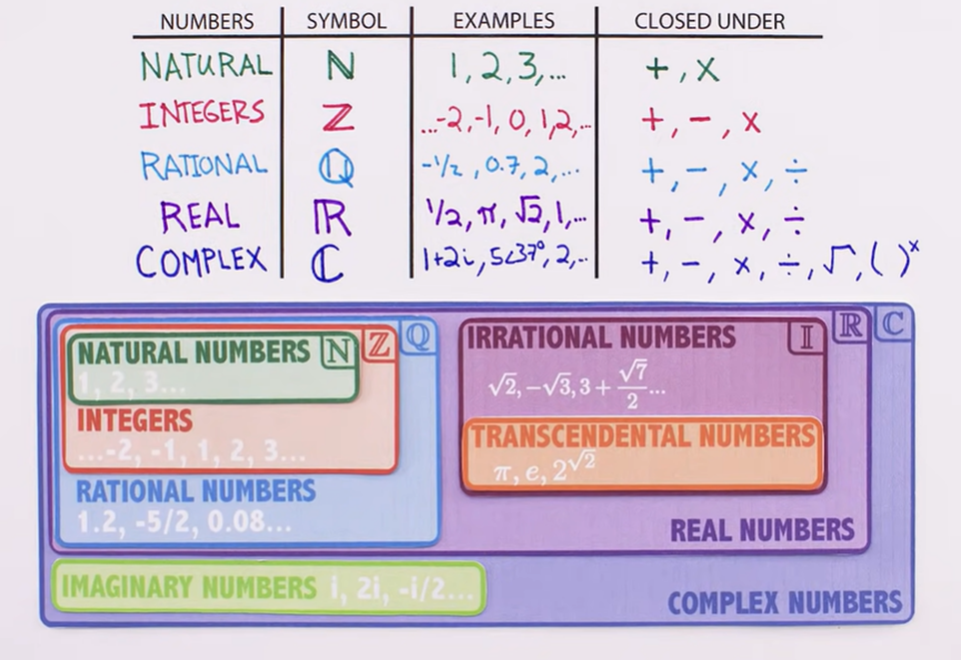
Complex Numbers
Welch Labs – Imaginary Numbers are Real (Videos)