Creating icons from schematics in Electric can be very helpful to organize (visually) your schematics as they start to become more complex. Icons also help abstract the functionality of a circuit, helping with the overall understanding of your project.
Export Input and Output Variables #
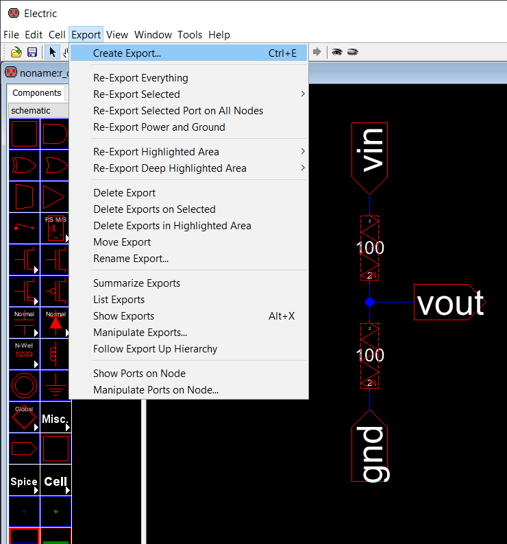
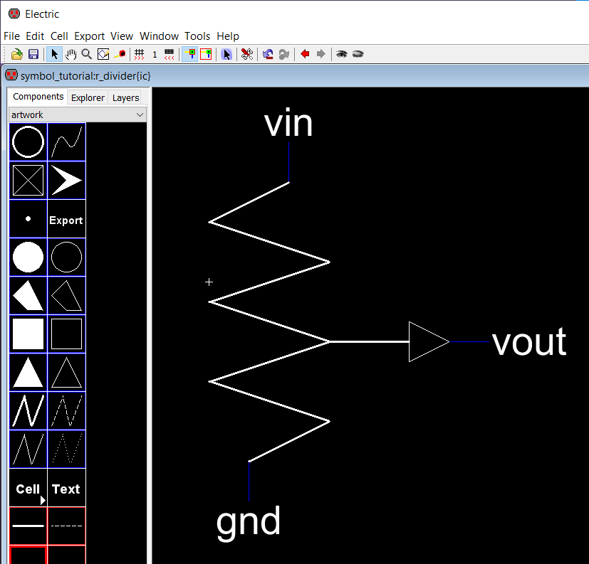
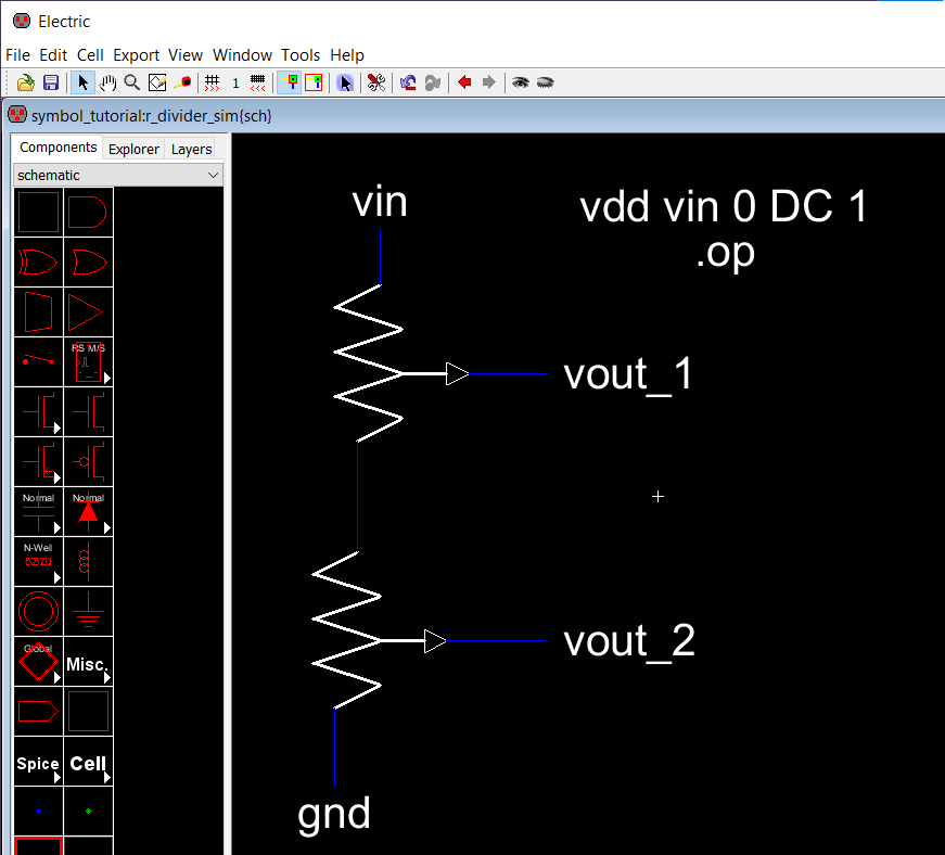
Let's go over a simple circuit, a voltage divider, and create the icon for the schematic below. The inputs and outputs of your schematic should be exported with the create export command. In this case, I created a vin, vout and gnd using that create export command. You can apply this command to a wire, Wire-Pin or an Off-Page component.
Create Icon #
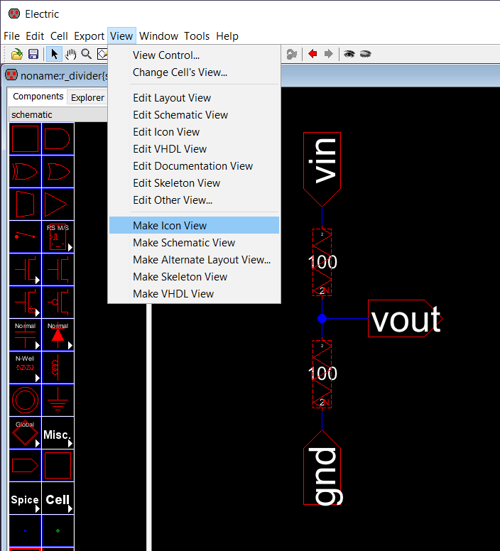
With your schematic selected, go to View -> Make Icon View
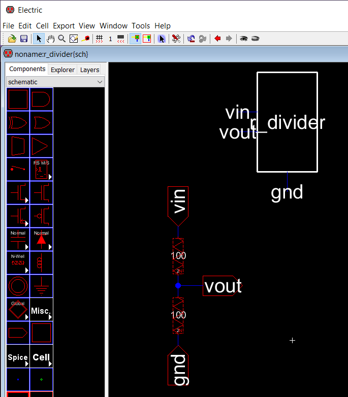
Electric will create a random icon with all the inputs and outputs that were exported and it will add a .ic file under the Explorer tab.
Edit Icon #
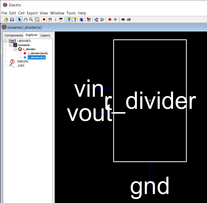
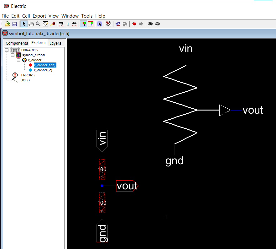
To edit the icon, go to the Explorer tab and double click on the .ic file.
You can now use the Components tab to design/modify the icon to your taste. If you want to create icons that are not predefined shapes, you need a little bit more patience and reuse and modify some of default components to achieve the desired shape.
The icon on the schematic gets updated automatically
Use Icon #
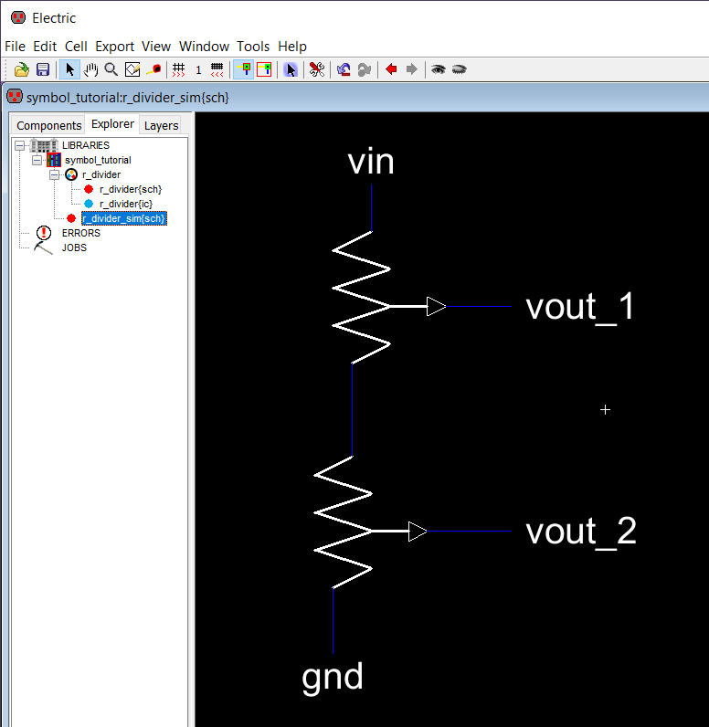
To use the new icon, create a new schematic and drag the icon as many as times as you want to your new design.
Simulate Icon #
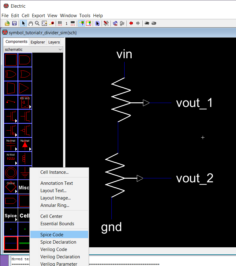
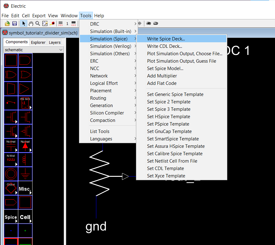
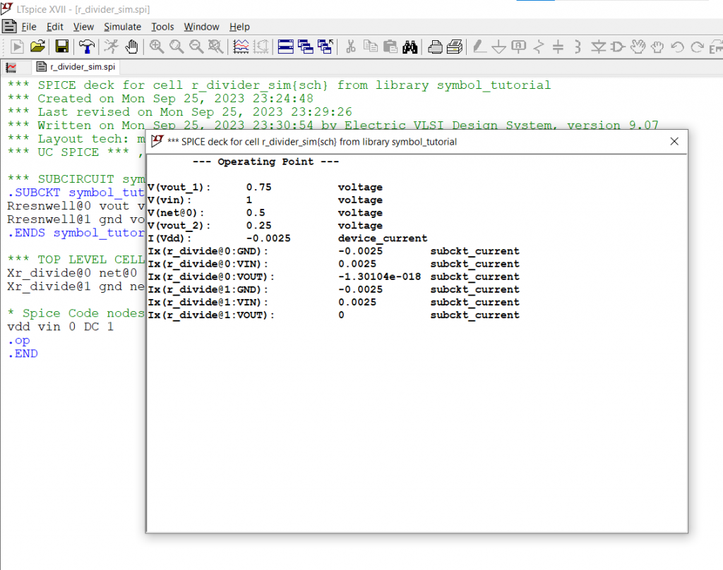
You can use spice commands to simulate the circuit and validate if the icon was successfully created.
References #
- "Example on how to create a symbol" (5:16) [YouTube Video]


