HC-SR04
Introduction
Let's interface a well known ultrasonic sensor, the HC-SR04 with the STM32F407 Discovery Board.
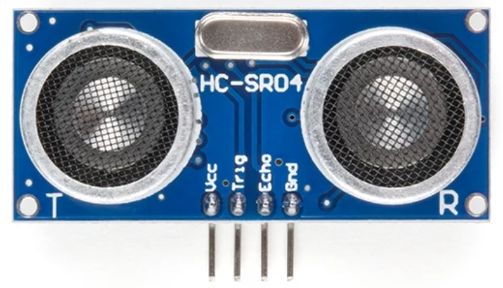
The pinout is straight forward, connect Vcc to 5V, GND for ground and the Trig and Echo pins will be connected to two GPIO pins on the STM32F407 board.
Note
The STM32F407 has 5V compatible GPIO pins. As long as we select the correct GPIO pin to interface the sensor, we don't need additional logic level shifters. Check this link to verify pins voltage compatibility
HC-SR04 Timing Diagram
I am going to trust that the reader will check the HC-SR04 datasheet for more information, and I am going to mention only the information that is relevant for the code that we will be developing.
The HC-SR04 has the following timing diagram:
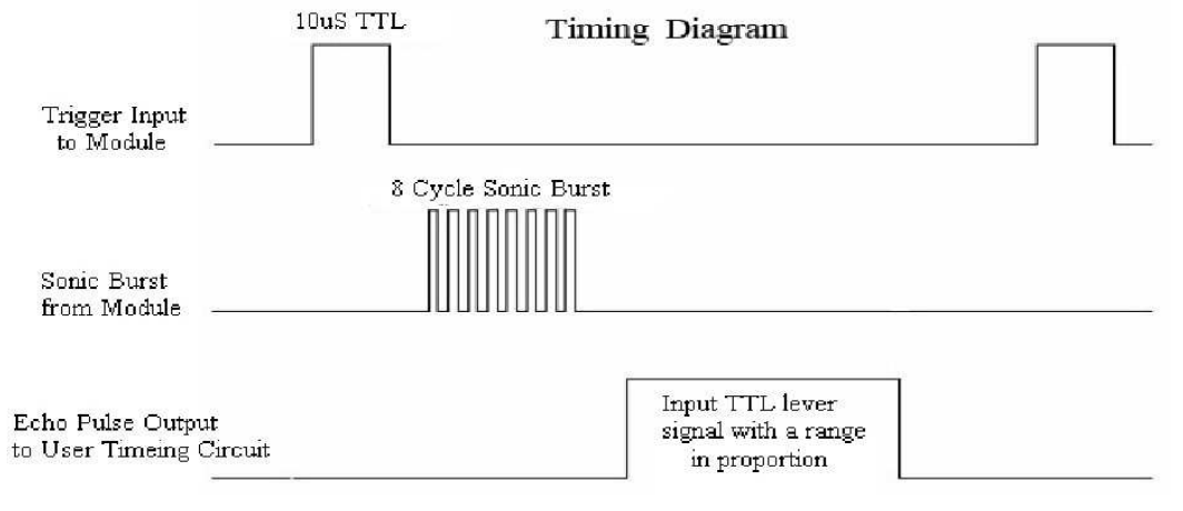
Our goal is to generate an 10uS pulse on the Trig pin and capture the time that the received pulse is high, on the Echo pin.
Embedded Diagram
The STM32F407 timers can work in different modes:
- Input Capture: Measures external signal timing (e.g. frequency or pulse width)
- Output Capture: Generate an event based on the timer's counter value
- PWM Generation: Create a periodic square wave signal with adjustable duty cycle
- One-Pulse Mode Output: Generate a single pulse output after a timer event
- Counter Mode: Basic counting functionality for time delays or triggering events
- Repetitive PWM Mode: Generate periodic PWM signals
- Encode Mode: Decode quadrature encoder signals for position and speed measurement
For this case, let's use two timers:
- Timer 1 set as one-pulse mode. It generates a 10uS pulse on channel 1. In this version, the pulse is not continuous. We need to use channel 2 of timer 1 to trigger the pulse whenever we want.
- Timer 2 set as input capture to measure the time that the received pulse is high. This counting is monitored inside an interrupt routine to alleviate processing time on the main loop.
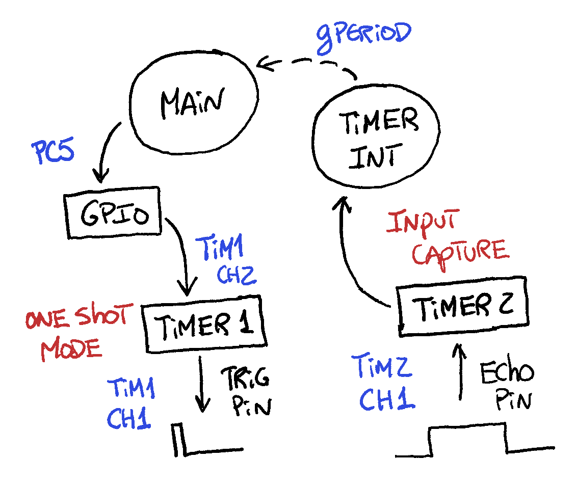
The diagram below shows the hardware and GPIO (squares) involved in this activity, and also shows how that hardware interacts with code (circles) under the STM32F407. It is an attempt to demonstrate the resources used at the software and hardware level and how the connections are done between them.
Timers Requirements
Before setting up the values for the hardware on CubeMX, let's understand if timer 1 and timer 2 can meet the timing requirements to interface the HC-SR04.
Timer 1 Specs
Timer 1 needs to generate a pulse of 10$\mu s$.
Timer 1 is connected to the APB2 bus that runs at 168MHz. Timer 1 is a 16bits timer, which means that it will count up to $2^{16}$.
We can apply a prescaler of 168 to get a counter frequency of 1MHz. This gives us a $1\mu s$ resolution.
Timer 2 Specs
Timer 2 needs to read a pulse that can vary from a distance of 2 cm up to 4m (400 cm). To convert distance to time, the datasheet gives 3 formulas. Since the specs are in cm and the timers will run in seconds, let's use the formula $\frac{\mu s}{58}=cm$ .
| Distance | $\mu s$ | |
|---|---|---|
| min | 2 cm | 116 |
| max | 400 cm | 23200 |
Timer 2 is connected to the APB1 bus that runs at 84MHz. Timer 2 is a 32bits timer, which means that it will count up to $2^{32}$.
Since the formula that we are using to convert time to cm is in $\mu s$, we can setup Timer 2 to run at a resolution of $1\mu s$. To achieve this, we set Timer 2 prescaler to 84, which will divide $\frac{84MHz}{84}=1MHz$
With $1\mu s$ resolution, we need to count at least up 23200, which equates to $23200 \mu s$. If we set Timer 2 counter to 65535, that give plenty of time to capture the maximum pulse.
Board Configuration
We are in good shape to configure the timers for our application.
Note
If you don't know how to create a project using STM32CubeIDE, check the articles under STM32CubeIDE -> Version2.1 -> Create New Project
Timer 1 Config
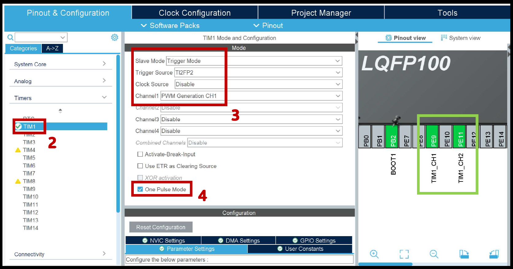
- Set a GPIO pin as output and label it as "PULSE_TRIG"
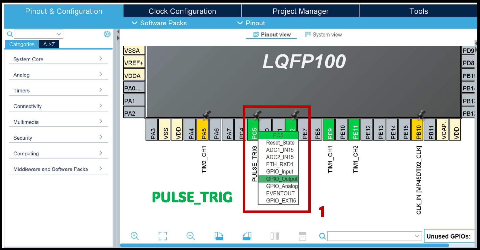
- Set Timer 1 slave mode as "Trigger Mode"
- Trigger Source as "TI2FP2"
- Channel 1 as "PWM Generation CH1"
- Enable "One Pulse Mode"
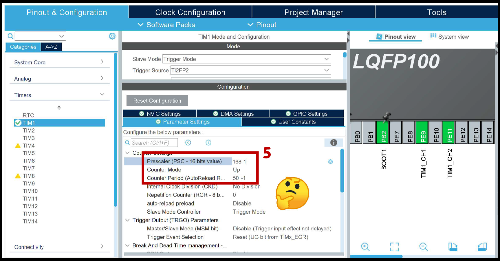
- Set the prescaler to 168 - 1, which makes the counter with $1\mu s$ resolution
- Set Counter Period to 50 - 1, which generates a 50$\mu s$ PWM period
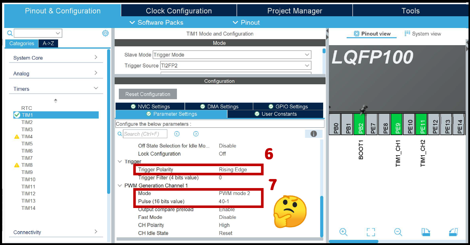
- Trigger Polarity will be "Rising Edge"
- Set Mode to "PWM mode 2"
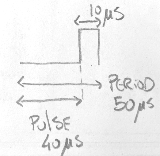
- Set Pulse value to 40 - 1, which equates to start the pulse 40$\mu s$ later translating to a pulse of 10$\mu s$ out of a 50$\mu s$ PWM period. It is the duty cycle of a PWM waveform but inverted.
Note
You can introduce different values on the above steps, as long as the math equates to generating a 10$\mu s$ pulse
Timer 1 Code
For the code, go to your main function:
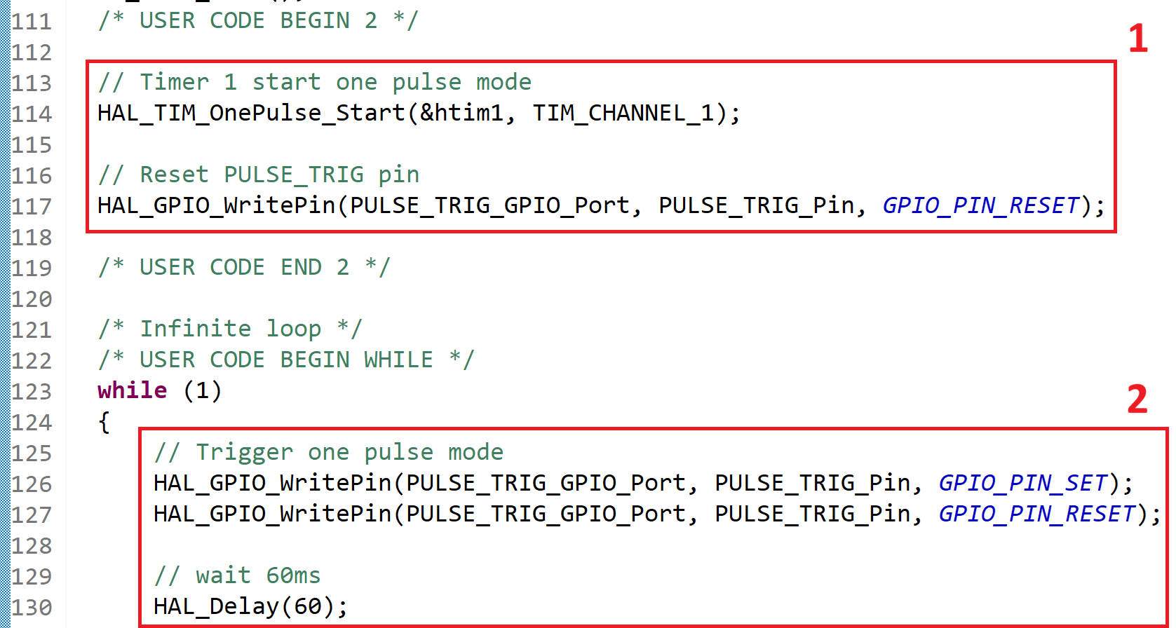
- Start timer 1 as one pulse mode
- Reset the PULSE_TRIG GPIO
- On the while loop, trigger the pulse and wait 60ms until you repeat the process
Note
Make sure that you connect a wire between PULSE_TRIG pin (PC5) and TIM1_CH2 pin (PE11). The output of the pulse will be on TIM1_CH1 pin (PE9).
Timer 1 Oscilloscope
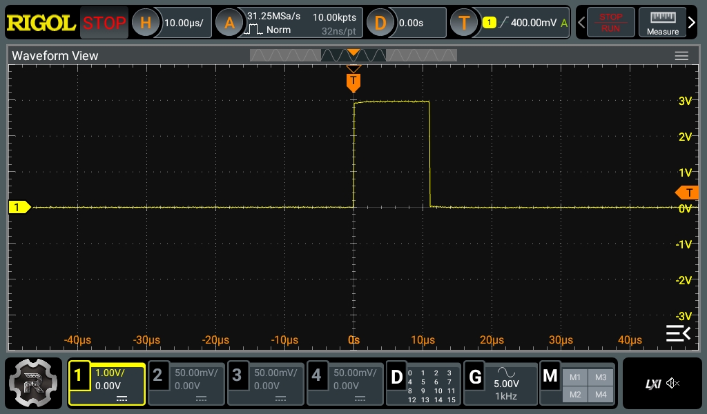
To confirm that we are generating a 10$\mu s$ pulse, connect an oscilloscope to TIM1_CH1 pin (PE9).
Connect pin PE9 to the HC-SR04 and a second oscilloscope probe to the Echo pin and confirm that you are reading the right time - distance values.
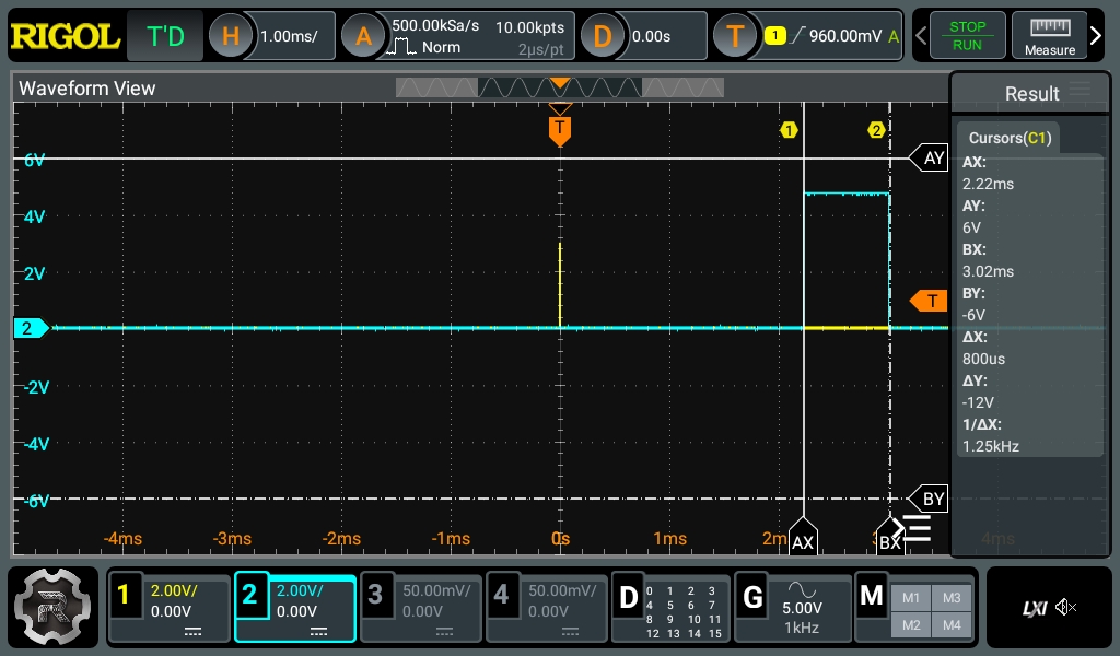
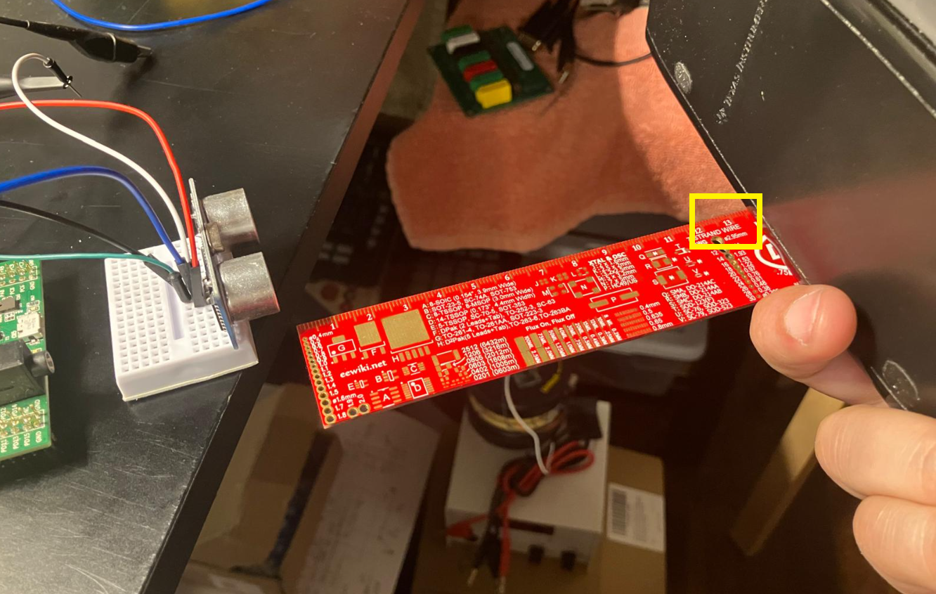
For a 800$\mu s$ Echo pulse, the object should be at 13.79cm
Timer 2 Config
- Set PA0 as "TIM2_CH1"
- Set Channel 1 to "Input Capture direct mode"
- Set the prescaler to 84 - 1, which makes the counter with $1\mu s$ resolution
- Set Counter Period to 65536 - 1, for a maximum count of 65535 $\mu s$
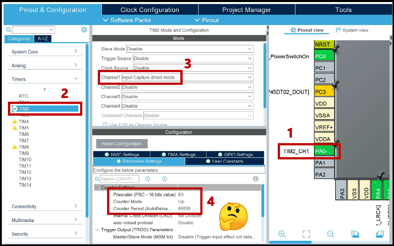
- Set Polarity to "Both Edges"

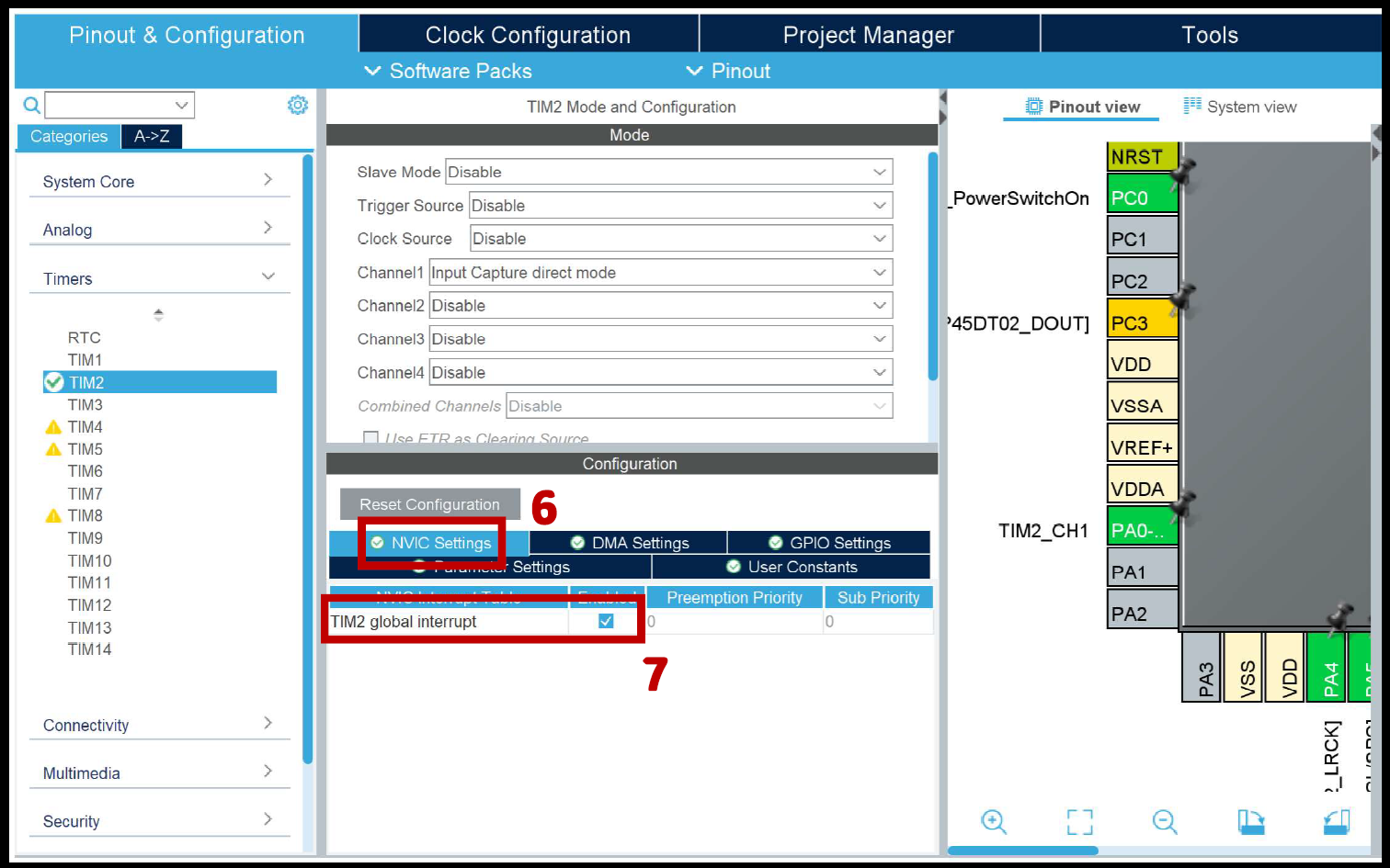
- Enable the "TIM2 global interrupt"
Timer 2 Code
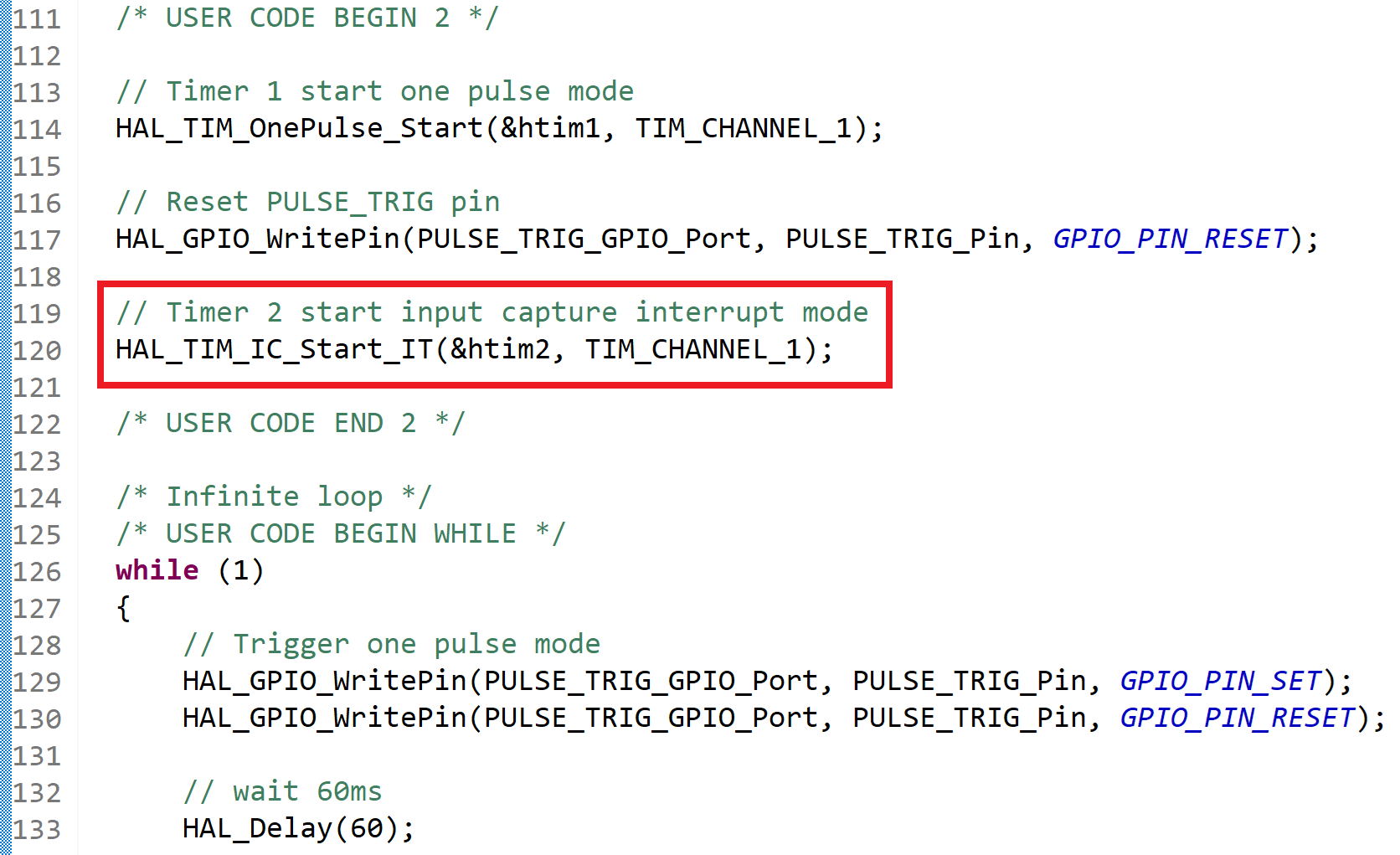
For the code, go to your main function:
- Add the line that starts timer 2 as input capture mode
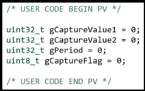
- Declare these global variables
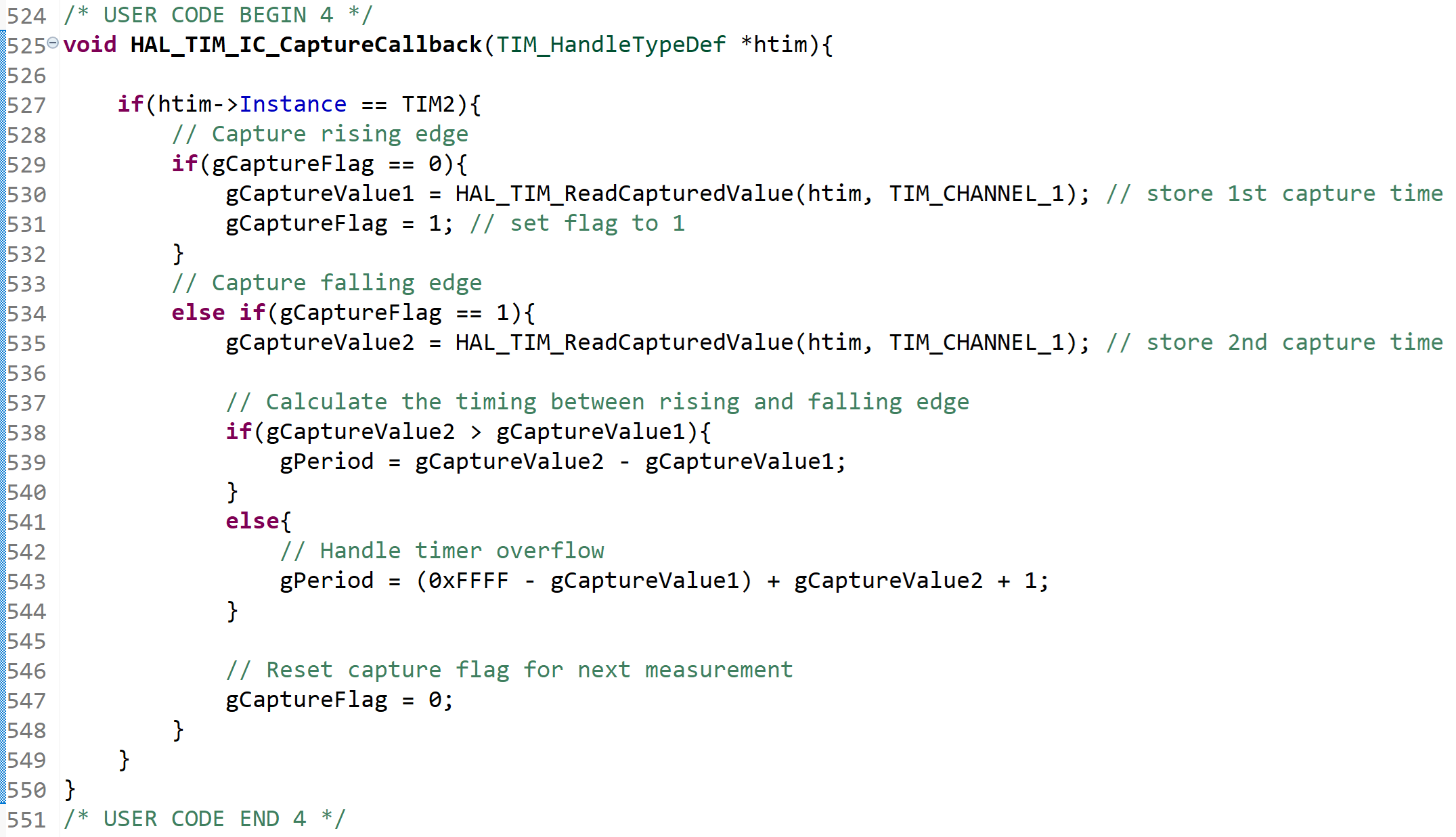
- Add a callback function for the interrupt routing that will handle counting the time that the pulse is high by monitoring the rising and falling edge of the pulse.
Debug
To track the timings in real time, run the code in debug mode and monitor your global variables under the "Live Expression" tab
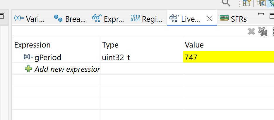
The result above is in $\mu s$, convert it to cm by using the equation on the datasheet.
Have fun 🙂