Arduino UNO – Timers
The Arduino Uno board is based on the ATmega328P microcontroller, which has three timers available for various timing and PWM operations. To follow along with this article, I recommend opening the datasheet on the indicated pages when prompted.
Timer Peripheral Features
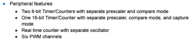
Right away on page 1, we can find that the ATmega328P has the following peripherals features related with timers:
The block diagram on page 6, gives the first hint on which timer are 8 or 16 bits.
- T/C 0 (Timer 0): 8-bit
- T/C 1 (Timer 1): 16-bit
- T/C 2 (Timer 2): 8-bit
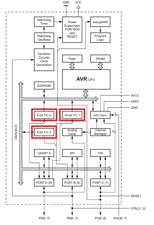
Hardware timers for a microcontroller, are typically built with counters [REF 1], increment logic, compare registers, control logic, and a clock source. The clock source is important to drive the internal logic (e.g.: flip flops).
The block diagram above, doesn't include that clock information, mainly because it would be confusing to have all that information concentrated in one diagram.
System Clock and Clock Options
If you scroll down the datasheet to page 24, "System clock and Clock Options", you will find a clock distribution block diagram.
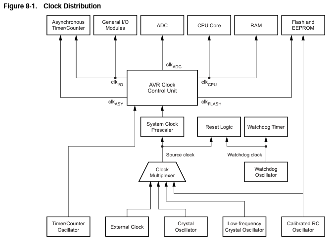
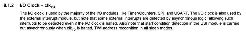
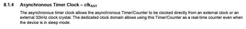
We can see that the timer/counter module is driven by the clk_I/O and clk_ASY, that comes from the AVR Clock Control Unit.
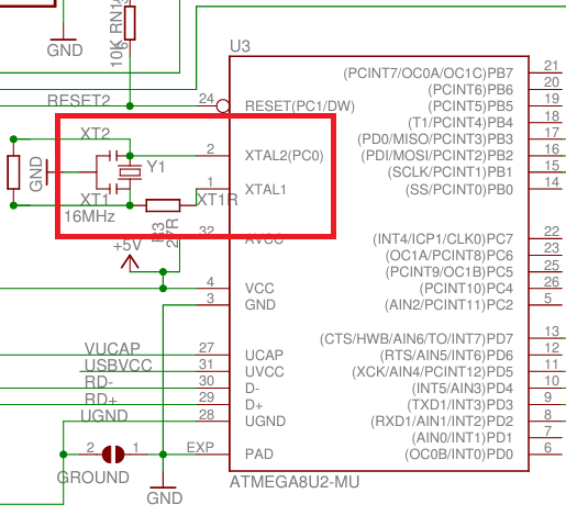
The Arduino UNO board has a 16MHz crystal oscillator that supplies the source clock to the AVR Clock Control Unit. You can find that information on the reference schematic design, where you can see a 16MHz ceramic resonator connected to the XTAL2 and XTAL1 from the MCU.
Between the AVR Control Unit and the Crystal Oscillator modules, there is a Clock Multiplexer and a System Clock Prescaler.
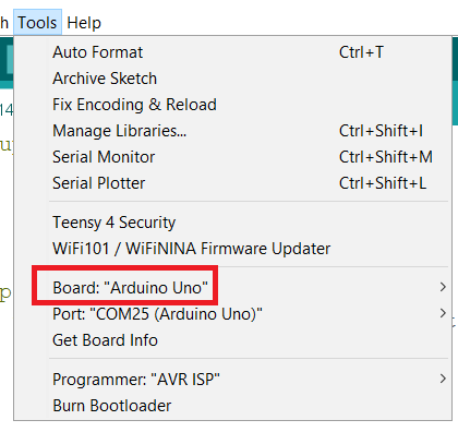
Note: up to this point, I still don't know where this Clock Multiplexer and System Clock Prescaler are being initialized or defined. All I know is when we set up the Board to "Arduino Uno" (image below), the AVR Clock Control Unit is providing a clk_CPU and clk_I/O of 16MHz. This section will be updated accordingly as soon as I find out where that information is.
You can add a couple of lines of code that reads the "F_CPU" macro to confirm the clk_CPU value of your Arduino UNO board.
void setup()
{
  Serial.begin(9600);

  uint32_t cpuFrequency = F_CPU;
  Serial.println(cpuFrequency);
}

void loop() {
}
Timers Clock Source
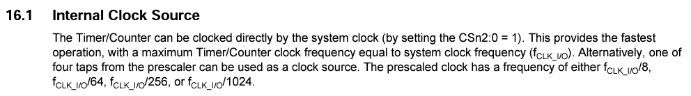
For Timer 0 and Timer 1, on page 114, mentions that it is possible to run the Timer/Counter clock frequency equal to the system clock frequency. That means clk_IO = clk_CPU.
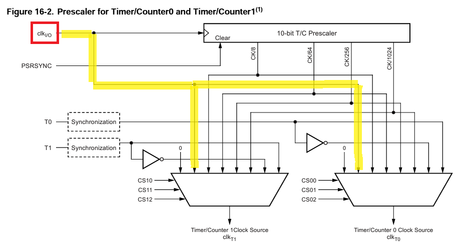
On page 115, we can see that it is possible to set the multiplexer to route clk_IO directly to clk_T1 and clk_T0.
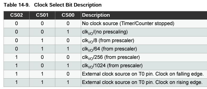
On page 87 you can find the clock select bit table for Timer 0.
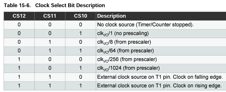
On page 110 you can find the clock select bit table for Timer 1.
For Timer 2, the clock source clk_T2 is by default equal to the MCU clock, clk_IO.
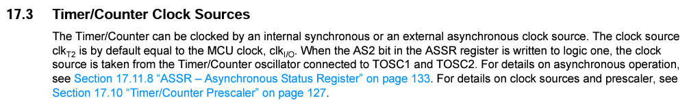
On page 127, we can see that it is possible to set the multiplexer to route clk_IO directly to clk_T2.
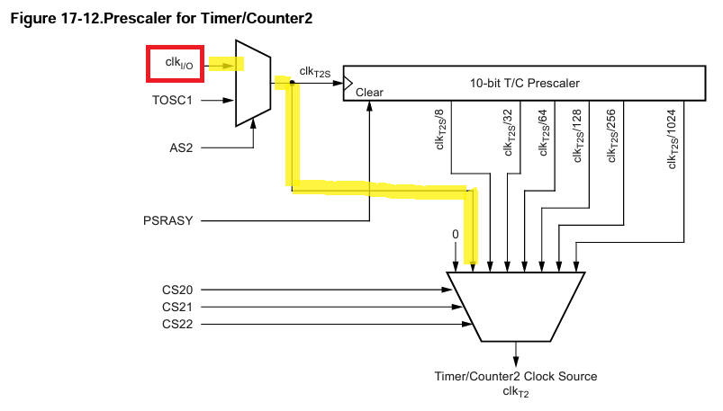
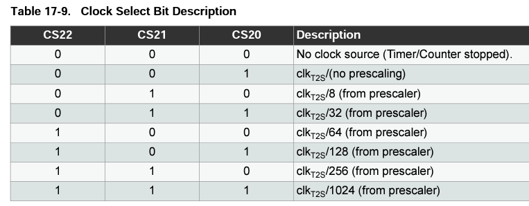
On page 131 you can find the clock select bit table for Timer 2.
Timers Modes
Any of the timers can be configured for different modes, such as Normal mode, CTC (Clear Timer on Compare Match) mode, Fast PWM mode, and Phase Correct PWM mode, depending on your specific requirements.
Timer/Counter 0
Timer/Counter0 is an 8-bit timer that is commonly used for generating PWM signals on pins 5 and 6 (OC0B and OC0A). It is also used by the millis() and micros() functions for timing operations.
Note: It is important to pay attention when to use Timer 0 properly. If in your code you are using any of the delay functions, Timer 0 becomes a critical peripheral to use because it is already being used by those functions.
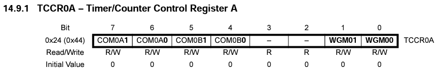
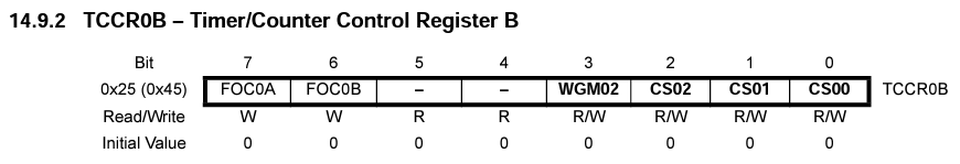
To select the mode, on page 86 you can find the waveform generation mode bit table for Timer 0.
And around this table you can find the registers that we need to change in order to select the desired functionality.
Timer/Counter 1
Timer/Counter1 is a 16-bit timer that provides more features and flexibility compared to Timer/Counter0. It is commonly used for generating PWM signals on pins 9 and 10 (OC1A and OC1B), as well as for various timing operations.
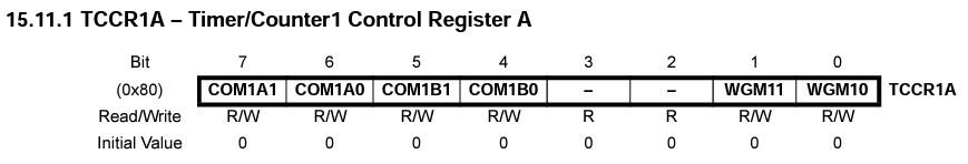
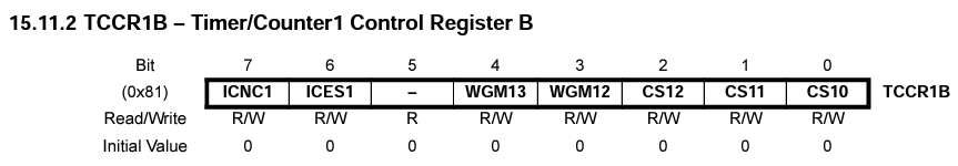
On page 109 you can find the waveform generation mode bit table for Timer 1.
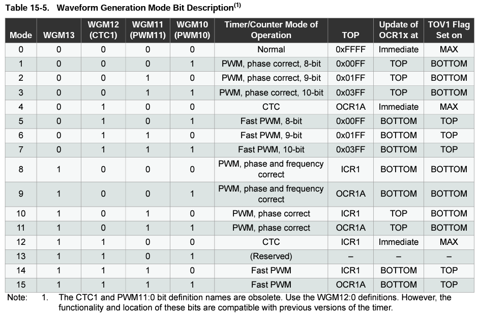
And around this table you can find the registers that we need to change in order to select the desired functionality.
Timer/Counter 2
Timer/Counter2 is another 8-bit timer similar to Timer/Counter0. It is commonly used for generating PWM signals on pins 3 and 11 (OC2A and OC2B).
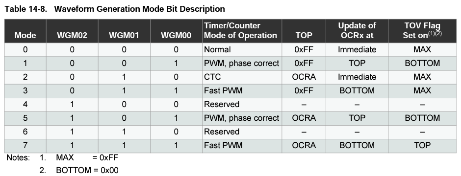
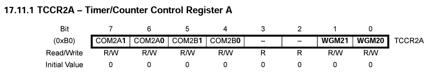
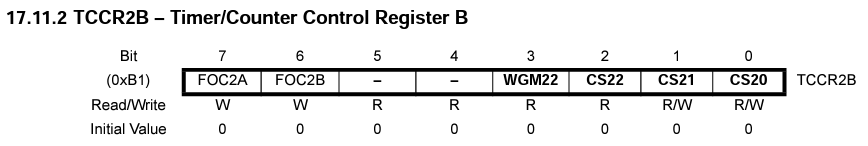
On page 130 you can find the waveform generation mode bit table for Timer 2.
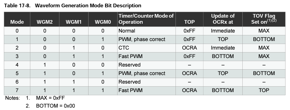
And around this table you can find the registers that we need to change in order to select the desired functionality.
CTC Mode Example
We are now in good shape to see an example, and hopefully we can understand how to set up the registers accordingly and understand the selected parameters.
This example will focus on using the timer in CTC mode that stands for Clear Timer on Compare Match.
Timer 1 @ 1sec
I hope the reader is familiar with how to set up interrupt routines using the Arduino IDE. For now, we will be focusing primarily on setting up and understanding timers for Arduino boards.
In the "Timers Clock Source" section, we can see that Timer 1 can run at max clock speed (16 MHz) or slower values if we select a prescaler value.
Since we are using the timer in compare mode, we need to use the OCR1A/B registers to input the value that we want the timer to count to.
On page 90 of the datasheet we can see that OCR1A/B are 16 bit registers, that means that the maximum value that we can enter is 

The goal is to set the timer to count up to 1 second. If we don't set up a prescalar and let the timer run at 16MHz, the maximum time that we can count will be 
To fix that, let's pick a prescalar of 256 (check table 15-6). Now the timer will be running at 

If you understand all the concepts up to this point, then all we need to do is the following:
- Line 23: load OCR1A with the value to count
- Line 24: Set the timer to CTC mode (table 15-5)
- Line 26: Set the prescalar to 256
- Line 27: Enable timer compare interrupt
#define LED  13

// Volatile Variables
volatile unsigned char gISRFlag1   = 0;

unsigned int gTimerCounter = 62500;  //1sec
char toggled = 0;

/**
 * @brief Setup peripherals and timers
 * @param
 * @return
 */
void setup() {
  // LEDs Pins
  pinMode(LED, OUTPUT);

  // Initialize Timer1 (16bit)
  // Speed of Timer1 = 16MHz/256 = 62.5 KHz
  noInterrupts();
  TCCR1A = 0;
  TCCR1B = 0;
  OCR1A = gTimerCounter; // compare match register 16MHz/256
  TCCR1B |= (1<<WGM12);   // CTC mode
  // Start Timer by setting the prescaler
  TCCR1B |= (1<<CS12);    // 256 prescaler
  TIMSK1 |= (1<<OCIE1A);  // enable timer compare interrupt
  interrupts();
}

/**
 * @brief Timer 1 ISR
 * @param TIMER1_COMPA_vect
 * @return
 */
ISR(TIMER1_COMPA_vect)  // Timer1 interrupt service routine (ISR)
{
  gISRFlag1 = 1;
}

/**
 * @brief Main Loop
 * @param
 * @return
 */
void loop()
{

  // Attend Button 2 ISR
  if(gISRFlag1 == 1)
  {
    // Clear Flag
    gISRFlag1 = 0;

    // Toggle LED
    toggled = !toggled;
    digitalWrite(LED, toggled);
  }
}
Timer 1 @ 1ms
As an exercise let's set up the timer to count at 1ms.
If you keep the prescalar at 256, to count up to 1ms you need the OCR1A value to be 
Let's change the prescalar to 8 (timer 1 will be running at 

#define LED  13

// Volatile Variables
volatile unsigned char gISRFlag1   = 0;

unsigned int gTimerCounter = 2000;  //1ms
char toggled = 0;

/**
 * @brief Setup peripherals and timers
 * @param
 * @return
 */
void setup() {
  // LEDs Pins
  pinMode(LED, OUTPUT);

  // Initialize Timer1 (16bit)
  // Speed of Timer1 = 16MHz/8 = 2MHz
  noInterrupts();
  TCCR1A = 0;
  TCCR1B = 0;
  OCR1A = gTimerCounter; // compare match register 16MHz/8
  TCCR1B |= (1<<WGM12);   // CTC mode
  // Start Timer by setting the prescaler
  TCCR1B |= (1<<CS11); // 8 prescaler
  TIMSK1 |= (1<<OCIE1A);  // enable timer compare interrupt
  interrupts();
}

/**
 * @brief Timer 1 ISR
 * @param TIMER1_COMPA_vect
 * @return
 */
ISR(TIMER1_COMPA_vect)  // Timer1 interrupt service routine (ISR)
{
  gISRFlag1 = 1;
}

/**
 * @brief Main Loop
 * @param
 * @return
 */
void loop()
{

  // Attend Button 2 ISR
  if(gISRFlag1 == 1)
  {
    // Clear Flag
    gISRFlag1 = 0;

    // Toggle LED
    toggled = !toggled;
    digitalWrite(LED, toggled);
  }
}
Timer 2 @ 2ms
Last example, let's use Timer 2, and set it to run at 2ms.
The subtle difference that it is easy to forget for Timer 2 is that it is an 8 bit timer. The register OCR2A is still a 16-bit register but we should only set it up to 
Don't forget to use the correct interrupt routine service too.
#define LED  13

// Volatile Variables
volatile unsigned char gISRFlag1   = 0;

byte gTimerCounter = 125;  //2ms
char toggled = 0;

/**
 * @brief Setup peripherals and timers
 * @param
 * @return
 */
void setup() {
  // LEDs Pins
  pinMode(LED, OUTPUT);

  Serial.begin(115200);
  uint32_t cpuFrequency = F_CPU;
  Serial.println(cpuFrequency);

  // Initialize Timer2 (8bit)
  // Speed of Timer2 = 16MHz/256 = 62.5 KHz
  noInterrupts();
  TCCR2A = 0;
  TCCR2B = 0;
  OCR2A = gTimerCounter; // compare match register 16MHz/256
  TCCR2A |= (1<<WGM21);   // CTC mode
  // Start Timer by setting the prescaler
  TCCR2B |= (1<<CS22) | (1<<CS21);    // 256 prescaler
  TIMSK2 |= (1<<OCIE2A);  // enable timer compare interrupt
  interrupts();
}

/**
 * @brief Timer 2 ISR
 * @param TIMER2_COMPA_vect
 * @return
 */
ISR(TIMER2_COMPA_vect)  // Timer2 interrupt service routine (ISR)
{
  gISRFlag1 = 1;
}

/**
 * @brief Main Loop
 * @param
 * @return
 */
void loop()
{

  // Attend Button 2 ISR
  if(gISRFlag1 == 1)
  {
    // Clear Flag
    gISRFlag1 = 0;

    // Toggle LED
    toggled = !toggled;
    digitalWrite(LED, toggled);
  }
}
GitHub Repository
References
- [REF 1] "Digital Counters", learnabout-electronics[Article]
- [REF 2] "Arduino Timer Interrupts - Explained with Timer 1 and Timer2 Examples", Microcontrollerslab Website [Article]
- [REF 3] "Using Arduino Interrupts – Hardware, Pin Change and Timer", DroneBotWorkshop [Article]
- [REF 4] "Pin Change Interrupt", ElectroNoobs [Article]