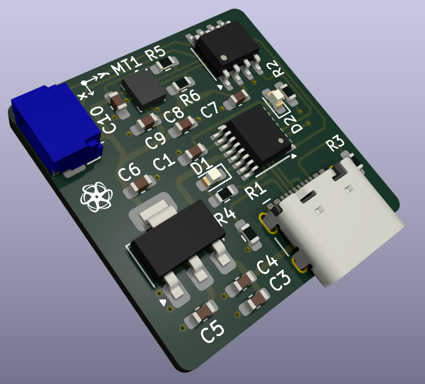
STM32C011J with ICM 42605
STM32C011J4M6 with IMU ICM 42605
✔️ Introduction
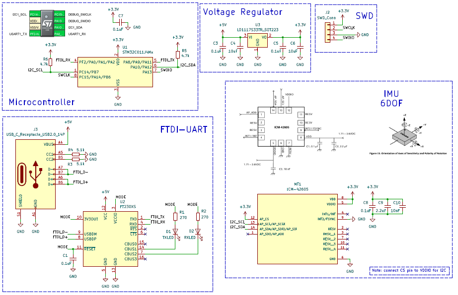
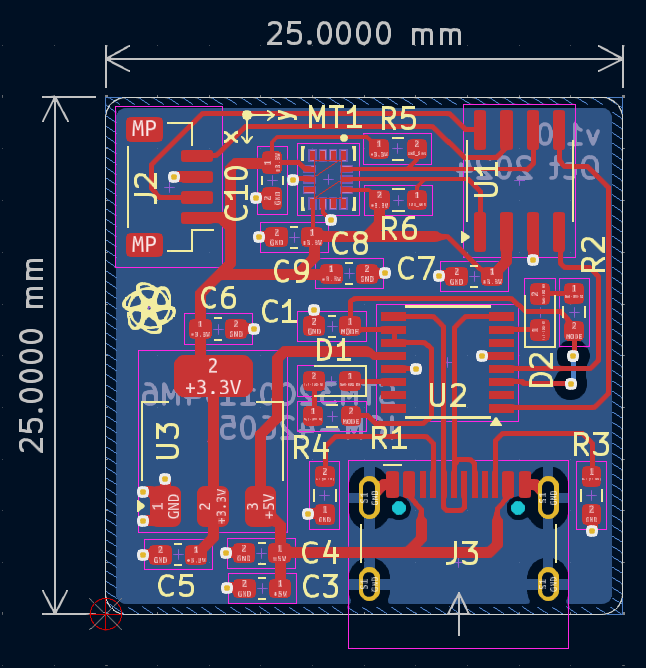
The goal with this project is to get familiar with the STM32C011J4M6 and the IMU 42605. This design can be used as a reference for projects that require an IMU on a small footprint PCB.
With that, the article jumps right away to the PCB design phase.
✔️ Assemble Stage
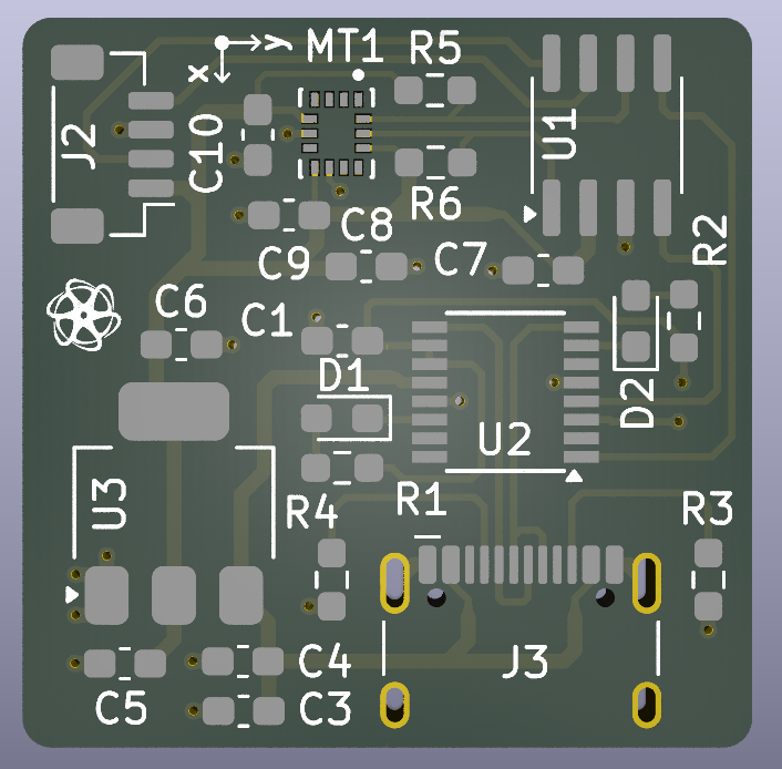
The boards were manufactured and assembled by PCBWay. As always a wonderful job.
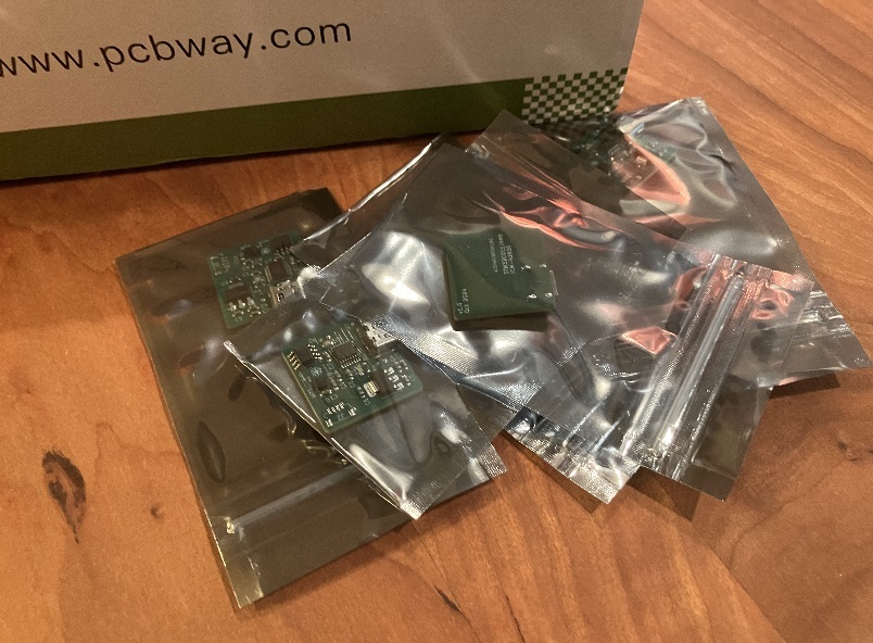
One of the aspects I appreciate most about PCBWay's assembly service is the consistent communication throughout the entire process, ensuring everything proceeds smoothly. For instance, after submitting the component list, PCBWay promptly confirmed receipt of all the requested components. If any files are missing, they notify me via email and respond quickly. During the assembly, they verify that all components are correctly soldered. Finally, once the board is ready for shipment, I receive a notification that it is on its way.
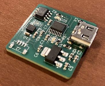
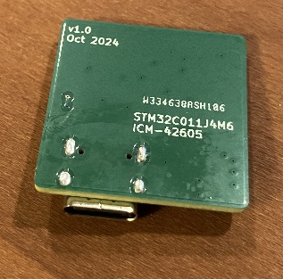
Assembling a board can be a time-consuming process, but the professional behavior and prompt communication from PCBWay instill confidence in their assembly service, making it a reliable choice for future projects with tight deadlines.
The JST connector was soldered onto the board manually after it was received. This was a deliberate design choice, as I could not source the part in time before submitting the files for production.


Quick Note: I forgot to include the resistors for the I2C lines. Fortunately, I was able to use the internal pull up resistors from the STM32C011J (around 50kΩ). All designs and files from the PCB design section were fixed accordingly.
✔️ Programmer/Debugger Adapter
To program the board I am using the ST-Link/V2 that has a 20-pin header connector that exposes all the pins needed for full JTAG and SWD support.


However, the STM32C011J board has a 1mm 4-pin JST connector. With that in mind I created an interface board to connect the SWD pins from the debugger to the STM32C011J. This interface board allows to connect 3 different types of SWD configurations:
- 3V3 / SWCLK / GND / SWDIO (4-pin JST)
- 3V3 / SWCLK / GND / SWDIO / RESET (5-pin JST)
- 3V3 / SWCLK / GND / SWDIO / SWO / RESET (6-pin JST)


✔️ Program the Board
Before using the STM32CubeIDE to write the test code, we need to do a small adjustment to the pinouts using the STM32CubeProgrammer.
Notice during the PCB design section, I assigned the UART_TX to pin 4 of the STM32C011J.
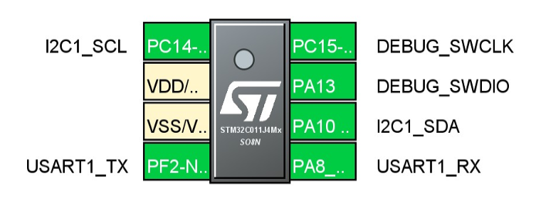
However, that pin can also be set to be the NRST pin which can cause the microcontroller to reset when we are using the UART if we don't disable that functionality [REF 2].

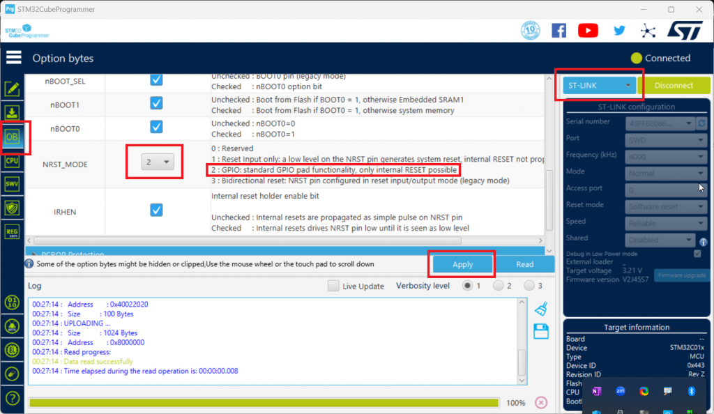
To configure the microcontroller pinout functionalities, start the STM32CubeProgrammer and connect to the board using the ST-Link mode. Once connected, select the "Option bytes" tab on the left, scroll down and set the NRST_MODE to 2. Press "Apply" and that is it, we are ready to program the board using the STM32CubeIDE.
✔️ Blink LED Test
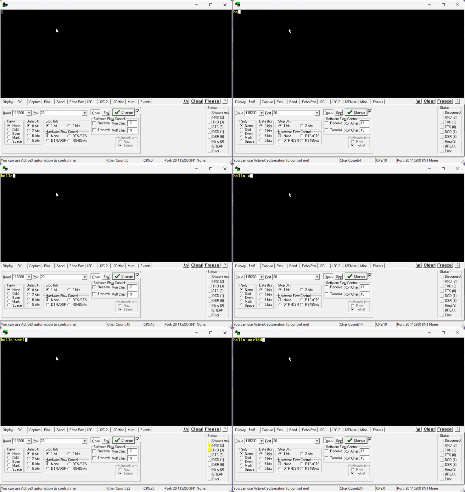
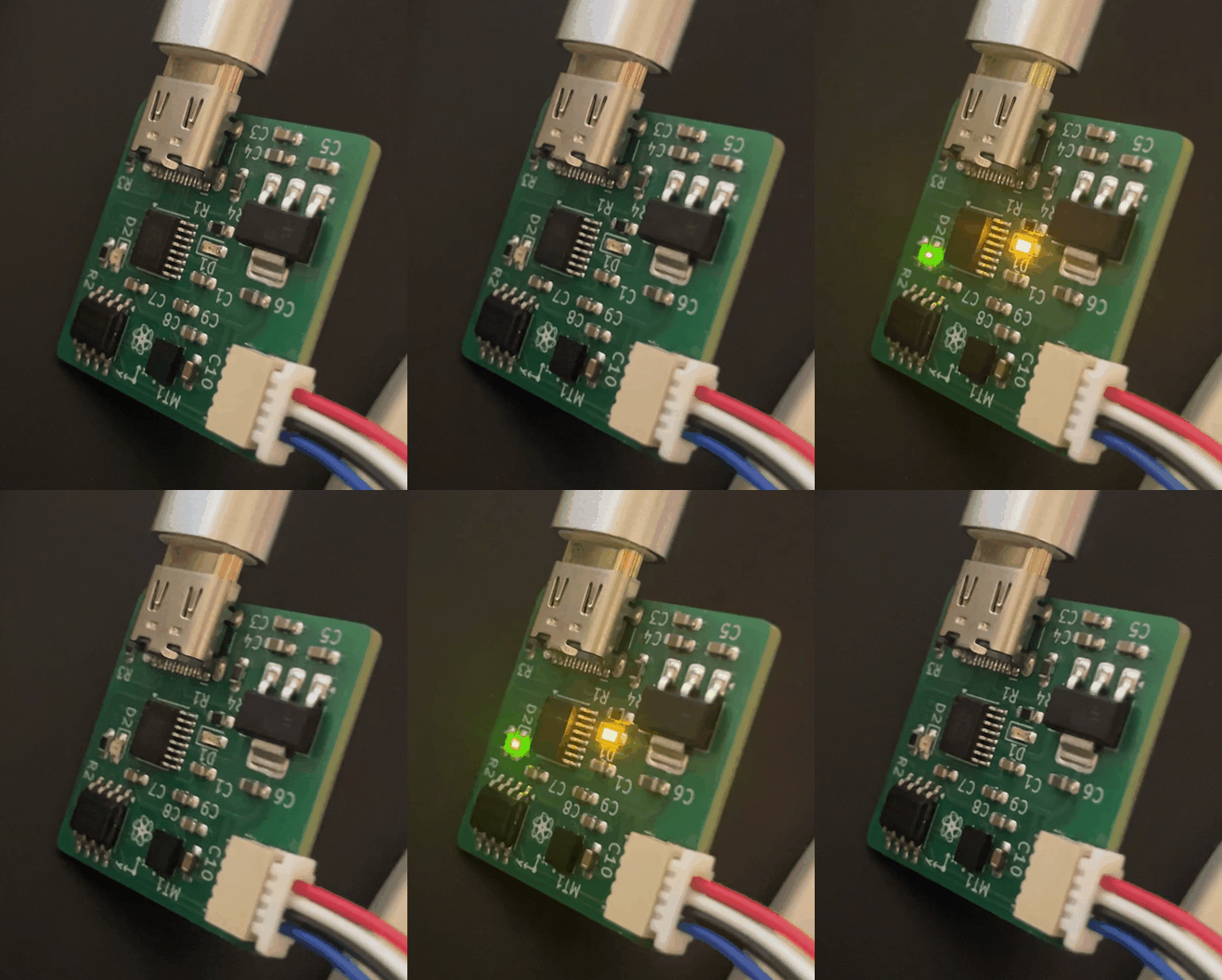
Since I don't have an LED available on this board, I will be doing the "Hello World" test using the UART. You can have access to code under the GitHub Repository section below.
✔️ IMU Test
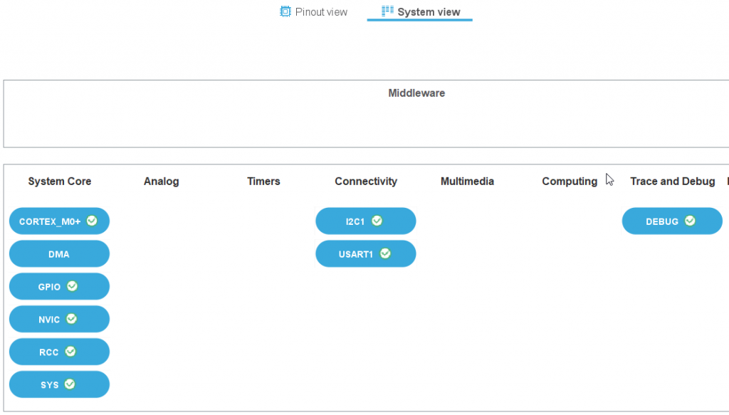
With the UART running, we can now shift our focus to interact with the IMU. I will start by showing the configuration done with the STM32CubeIDE.
Pinout and System View

UART Configuration

I2C Configuration

I2C GPIO Mode and Configuration

Code Observations
The code responsible for retrieving raw accelerometer and gyro data and transmitting it over UART is available in the GitHub Repository section. While a detailed explanation of the code is beyond the scope of this article, I will highlight a few interesting observations.
The STM32C011J has just 16KB of Flash, and I nearly maxed it out despite writing only a modest amount of code.

With that in mind, I had to write efficient drivers for interacting with the IMU and UART. The drivers included in this project are incomplete, and to fully leverage the capabilities of this IMU, I would recommend using a different microcontroller for interaction.
Debug
To ensure proper communication with the IMU and verify that I was receiving accurate data, I used the built-in STM32CubeIDE debugger to monitor the raw data stored in global variables.

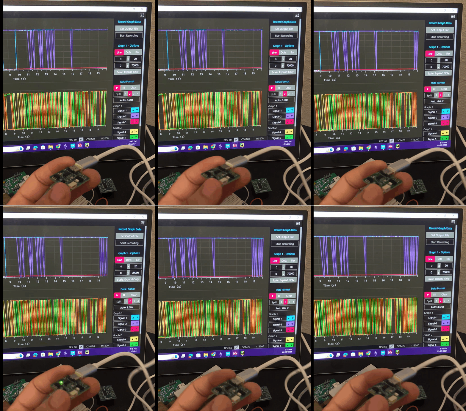
Serial Plotter
To plot the data being sent over UART, I used the Processing Grapher Program (Link)
✔️ GitHub Repository
✔️ References
- [REF 1] "Guide: Connecting your Debugger", Website [Article]
- [REF 2] "Troubleshoot Direction", Website [Forum]
- [REF 3] "Processing Grapher Program", Website [Software]
Sponsor

