Charge Pump
Charge Pump
✔️ Introduction
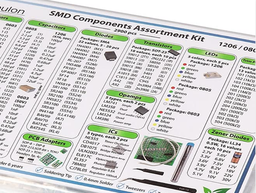
The motivation for this project comes after watching the video from Ben Eater on his YouTube channel about building a voltage multiplier and having around some SMD components from this box that I wanted to use.
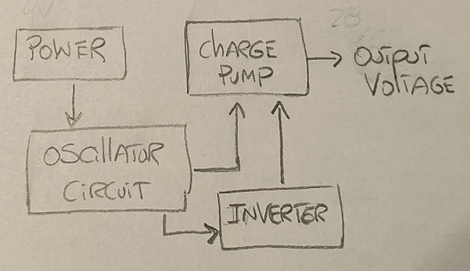
I recommend watching the video since it does a wonderful job explaining how a voltage multiplier works. However, the general block diagram for this project is below.
✔️ Design Stage
For the oscillator part of the circuit, I will be using the NE555 timer in A-stable mode and I will be using the reference design from the datasheet on page 11.
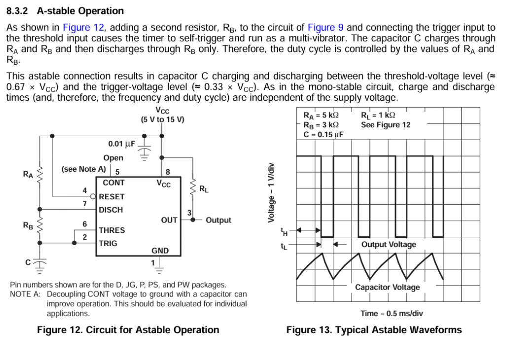
I picked the values of 

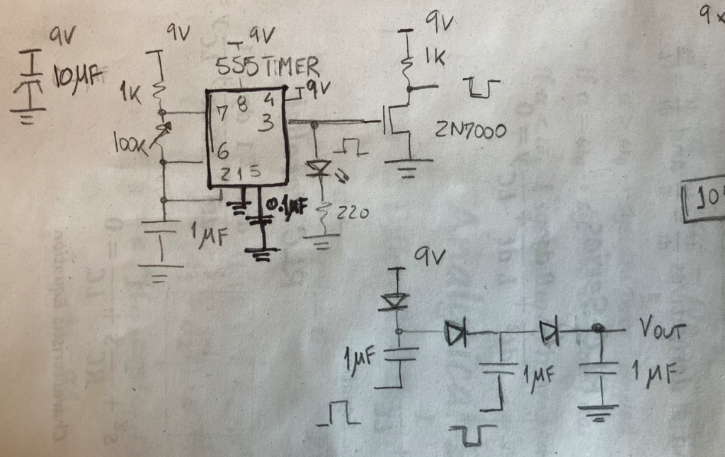
For the charge pump circuitry, I will follow Ben’s components values, since I have them available on the SMD assortment kit.
Unfortunately, the SMD assortment kit doesn’t have N-Channel transistors. With that, for the inverter, I will use the N-Channel (2N7002k).
Ben used 15 stages and increased the voltage from 9V to around 110V. Let’s do some testing and figure it out how many stages should I include in this design.
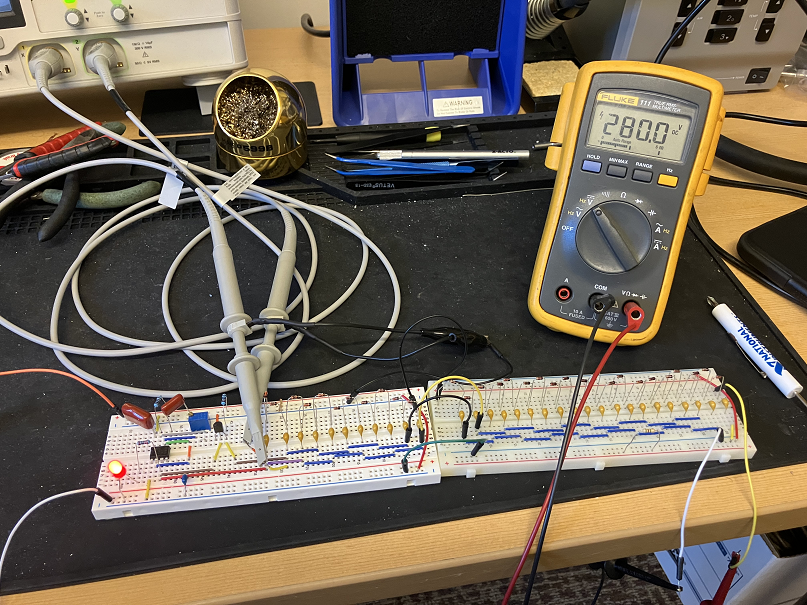
✔️ Prototype Stage
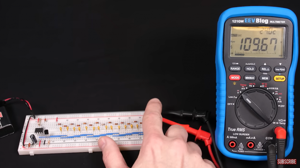
I built the prototype up to 30 stages, resulting with an output voltage of 280V.
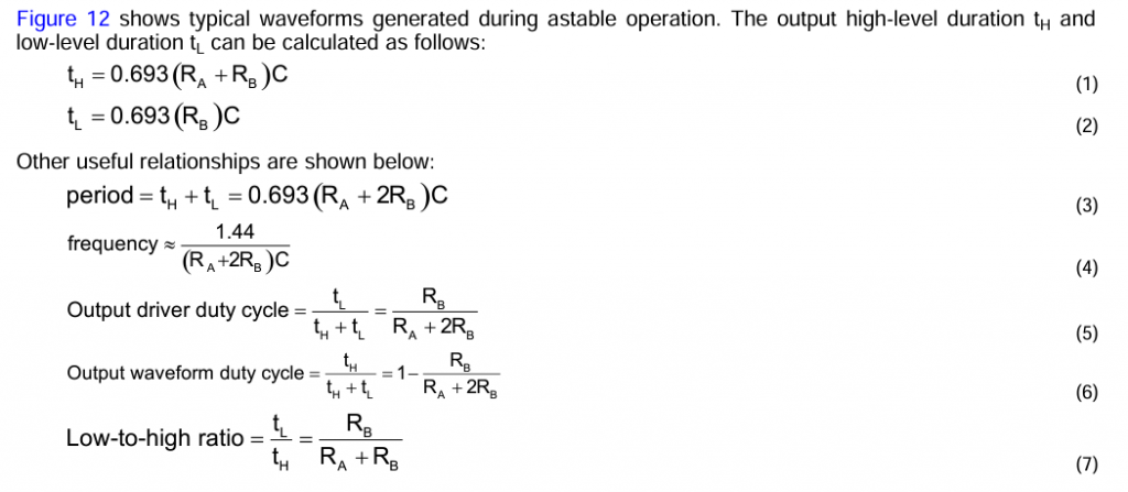
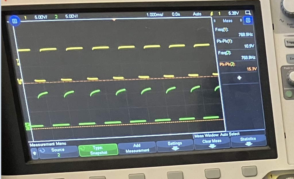
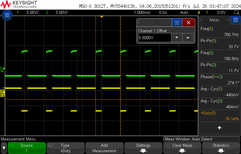
I set the NE555 to oscillate around 768Hz which sets a duty cycle around 76%. No particular preference on the frequency of oscillation for this test.
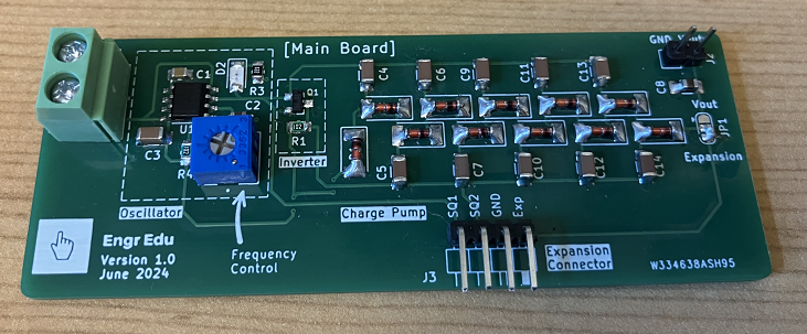
✔️ PCB Design
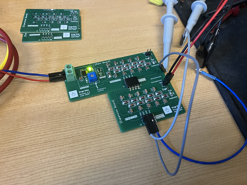
The design was divided into 2 parts: a main board with a 10-Stage charge pump and an expansion board with a 10-Stage charge pump. The expansion boards can stack on each other to create a bigger output voltage.
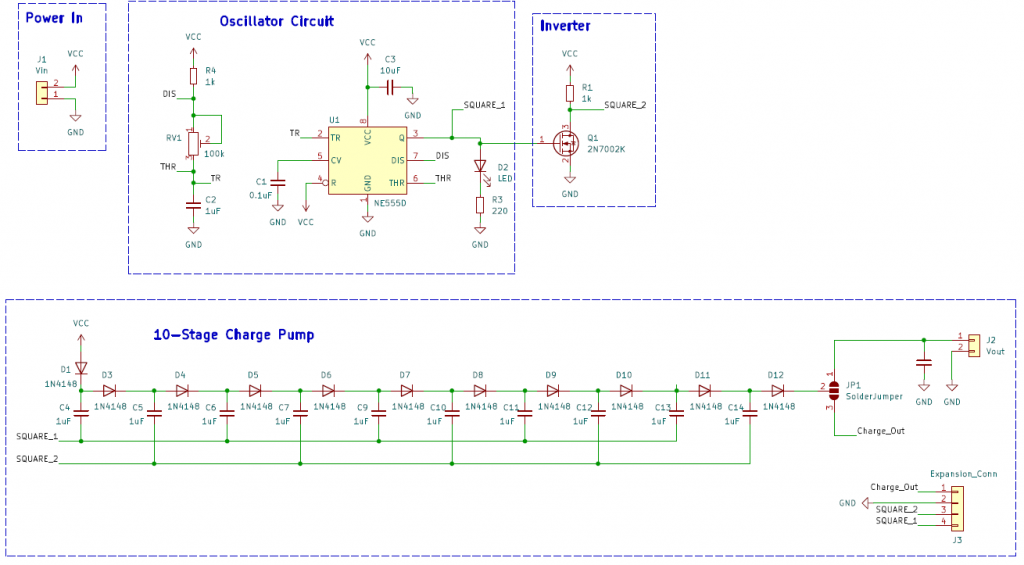
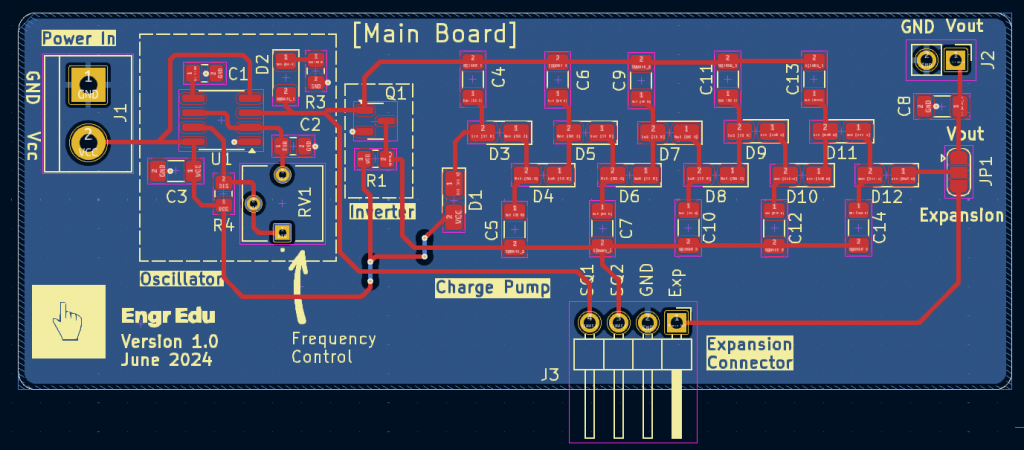
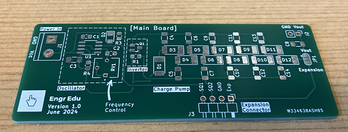
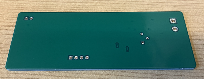
Main Board
Schematic (Zoom)
Layout (Zoom)
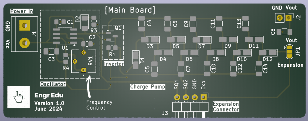
3D Rendering

Interactive BOM (Link)
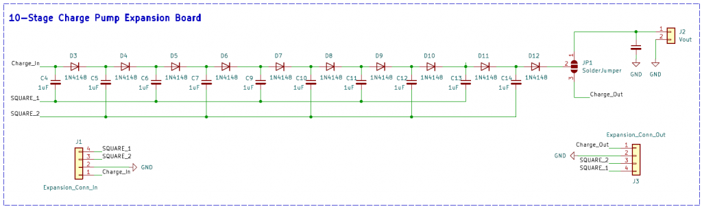
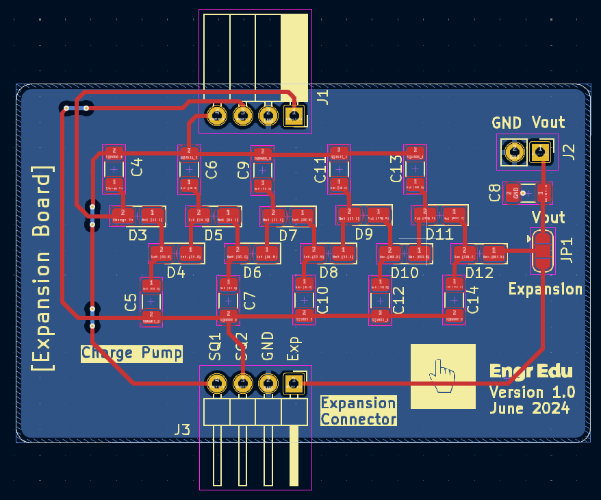
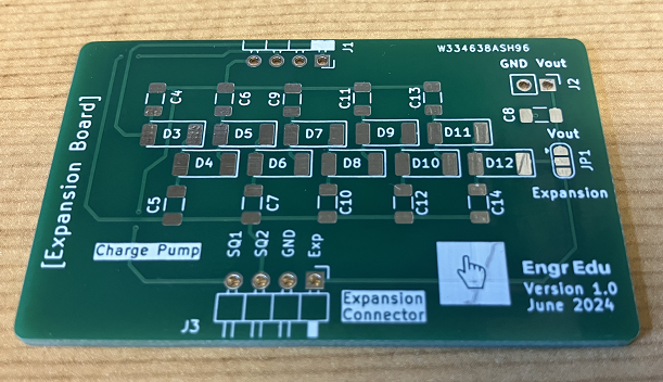
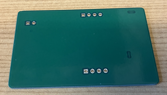
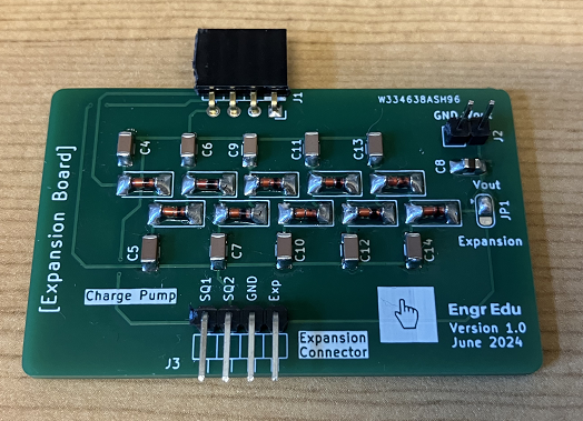
Expansion Board
Schematic (Zoom)
Layout (Zoom)
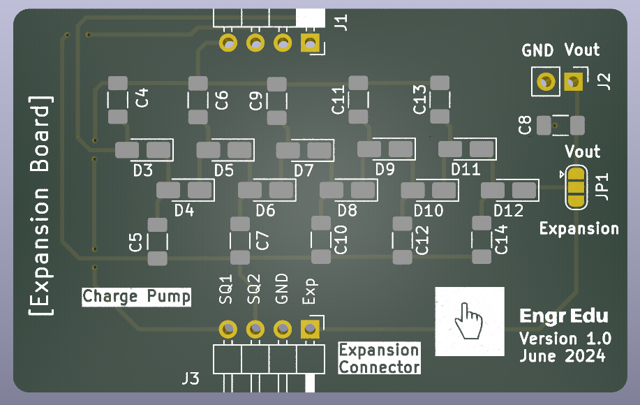
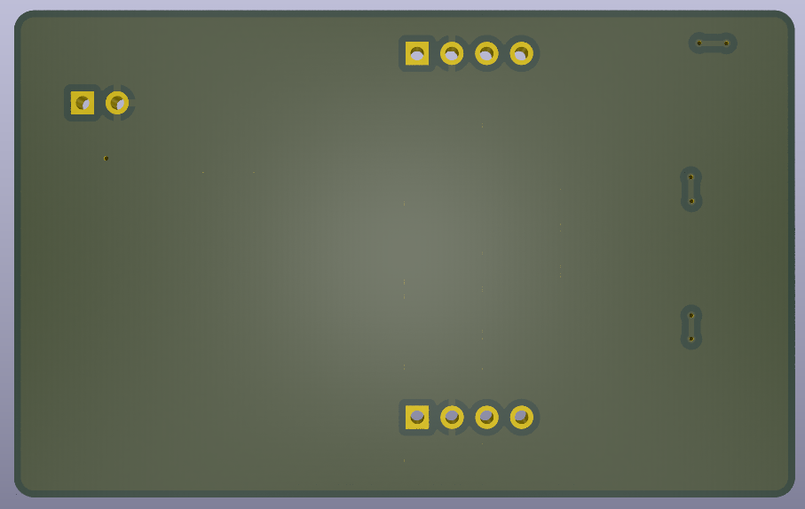
3D Rendering
Interactive BOM (Link)
Main Board + Expansion Boards (Fusion 360)
✔️ Assemble Stage
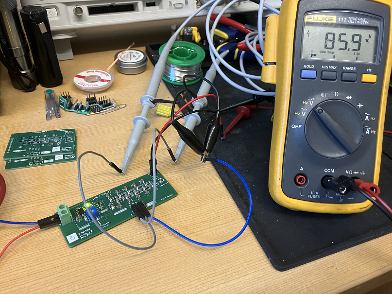
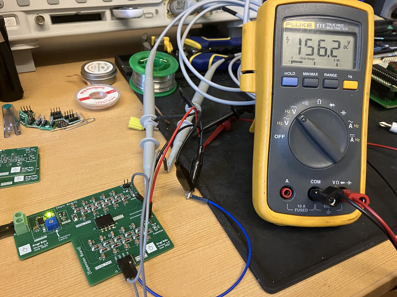
✔️ Testing Stage
Main Board
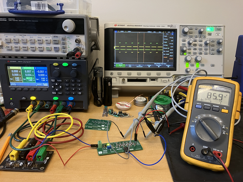
Main Board + Expansion Board
Oscilloscope
✔️ GitHub Repository
KiCad Files
✔️ References
- [Ref 1] “Let’s build a voltage multiplier”, Ben Eater YouTube Channel [Video]
Sponsor

Happy 10th Anniversary PCBWay. Thank you as always for your support, I appreciate it 🙏