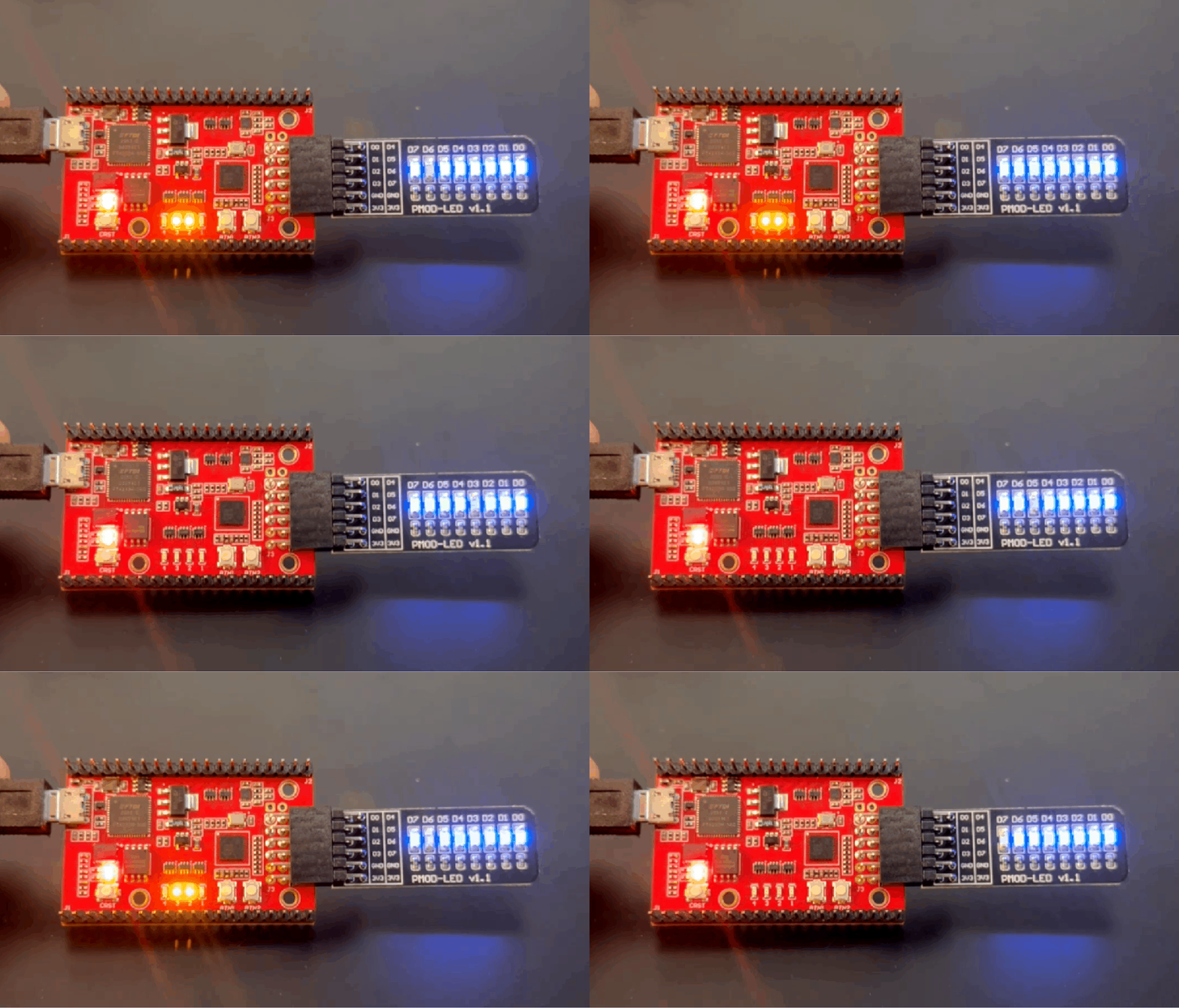
PMOD Blink LED
Note
To install the Xyloni USB drivers and EFINIX IDE follow the guidelines under this GitHub repository
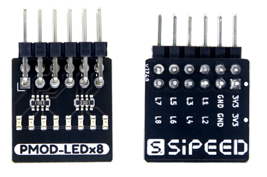
- For this project you also need the TANG PMOD-LEDx8 or a PMOD LEDx8 with equivalent pinout
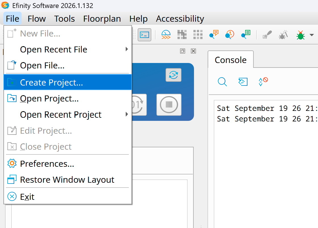
- Open EFINIX IDE.
Create a Project
- File-->Create Project...
- Set the project name, path and choose the model of your FPGA: Trion T8F81 C2
Note
Change the name of the project from ToggleLED to PMOD_BlinkLED.
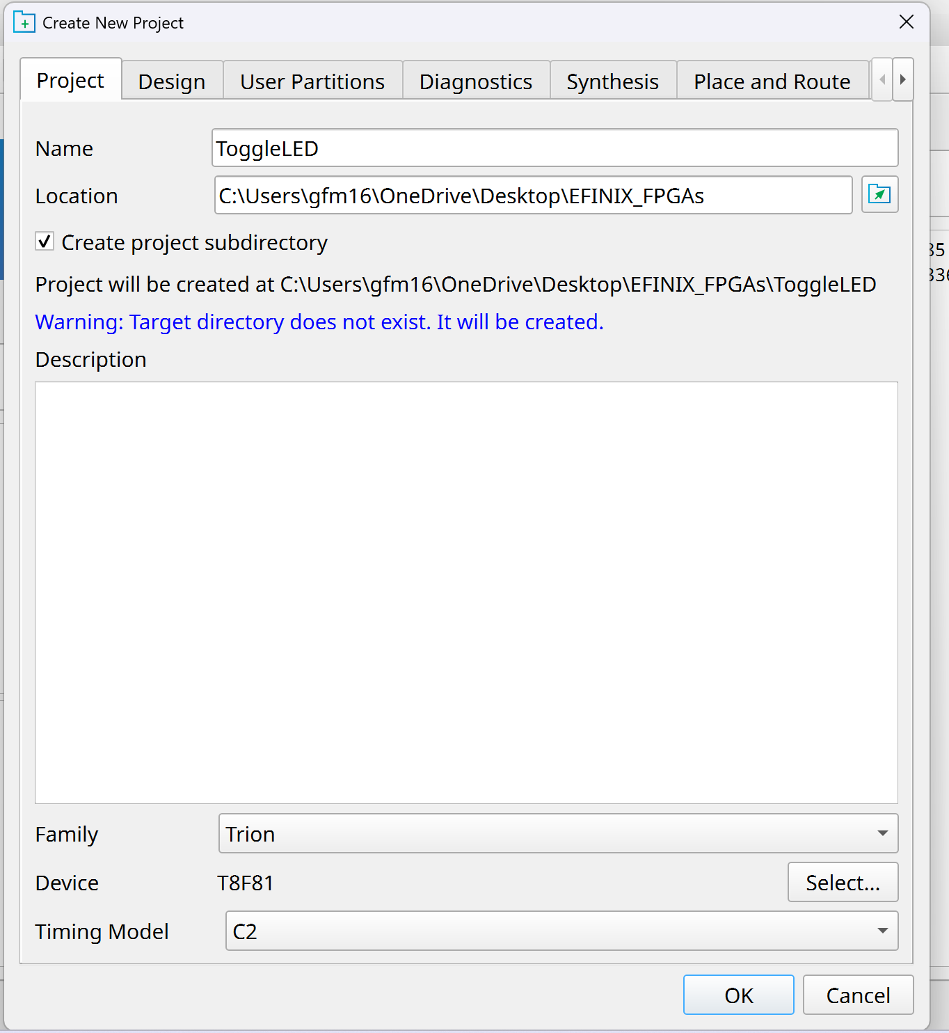
- Press Ok and finish.
Create the Top Level Module
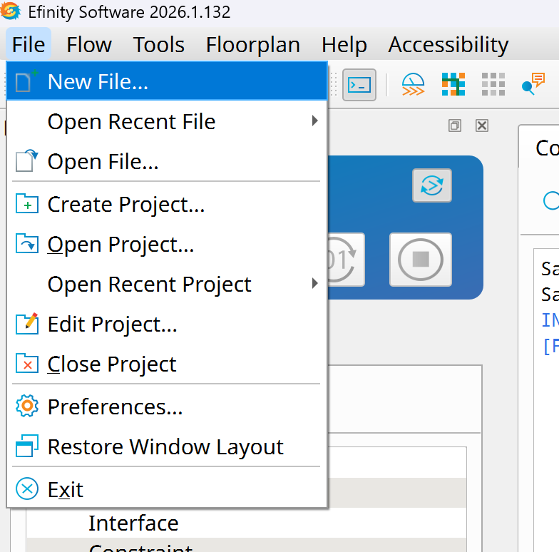
- Create a new Verilog file
- File --> New File...
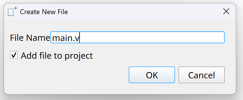
- I like to call the top level module "main.v"
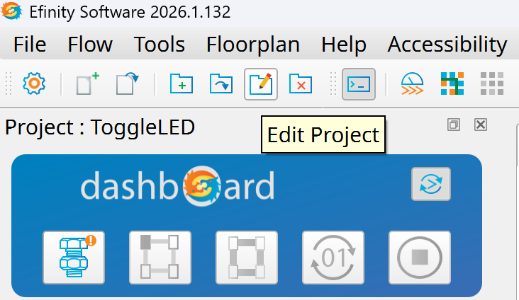
- Go to Edit Project
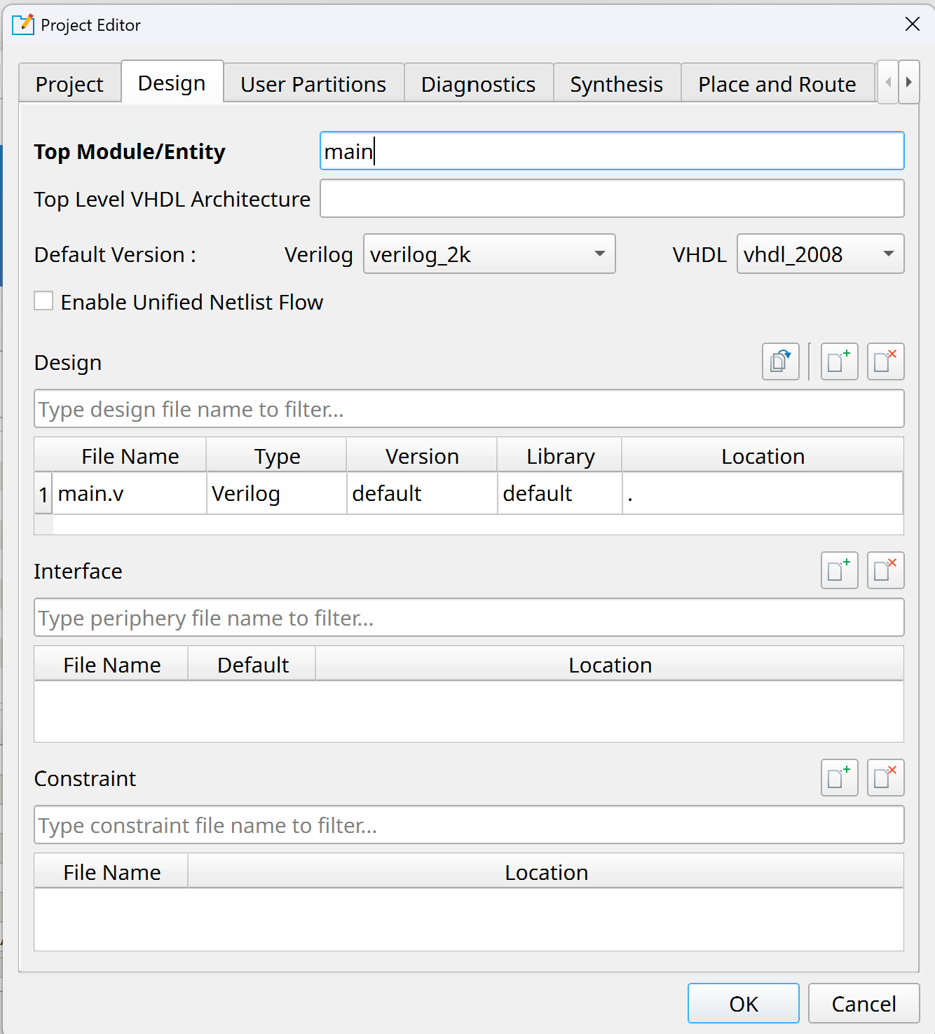
- Select the Design tab and change the Top Module/Entity to "main"
-
Press the Ok button
-
Write the code below under the main.v to toggle the onboard LEDs
module main(
    input clk,
    input [1:0] BUTTON,
    output [3:0] LEDY,
    output [7:0] LEDx8
);

    assign LEDY[0] = ~BUTTON[0];
    assign LEDY[3] = ~BUTTON[1];

    wire w_blink;

    counter C0(
        .clk_0(clk),
        .out(w_blink)
    );

    assign LEDY[1] = w_blink;
    assign LEDY[2] = w_blink;

    shiftRegister_8 SR8(
        .clk_0(clk),
        .out(LEDx8)
    );


endmodule

module counter(
    input  wire clk_0,
    output reg  out
);

    // 6,600,000 cycles = 200 ms at 33 MHz
    localparam integer COUNT_MAX = 6_600_000 - 1;  // External oscillator 33MHz
    //localparam integer COUNT_MAX = 2_000 - 1;  // for internal oscillator 10kHz

    reg [22:0] cnt;

    always @(posedge clk_0) begin
        if (cnt == COUNT_MAX) begin
            cnt <= 23'd0;
            out <= ~out;
        end
        else begin
            cnt <= cnt + 1'b1;
        end
    end

endmodule

module shiftRegister_8(
    input  wire clk_0,
    output reg [7:0] out
);

    // 6,600,000 cycles = 200 ms at 33 MHz
    localparam integer COUNT_MAX = 3_300_000 - 1;  // External oscillator 33MHz

    reg [22:0] cnt;

    // configure the power-up state of the flip-flops
    // substitute this with a reset button
    initial begin
        cnt = 0;
        out = 8'b00000001;
    end

    always @(posedge clk_0) begin
        if (cnt == COUNT_MAX) begin
            cnt <= 0;
            out <= {out[6:0], out[7]};
        end
        else begin
            cnt <= cnt + 1'b1;
        end
    end

endmodule
Floor Planner
- In order for FPGA to realize the functions of the code, the ports involved in the code must be bound to the actual pins of FPGA.
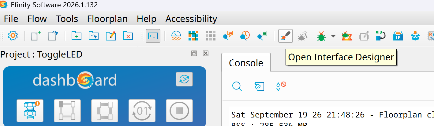
- Open the Interface Designer
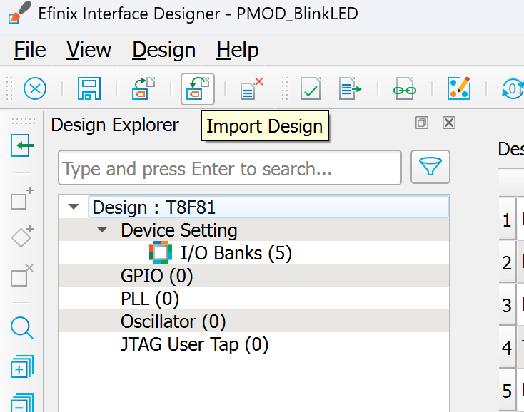
- This time, instead of assigning the pins one by one, we are going to import a csv file with the pins already assigned.
- Press the "Import Design" button
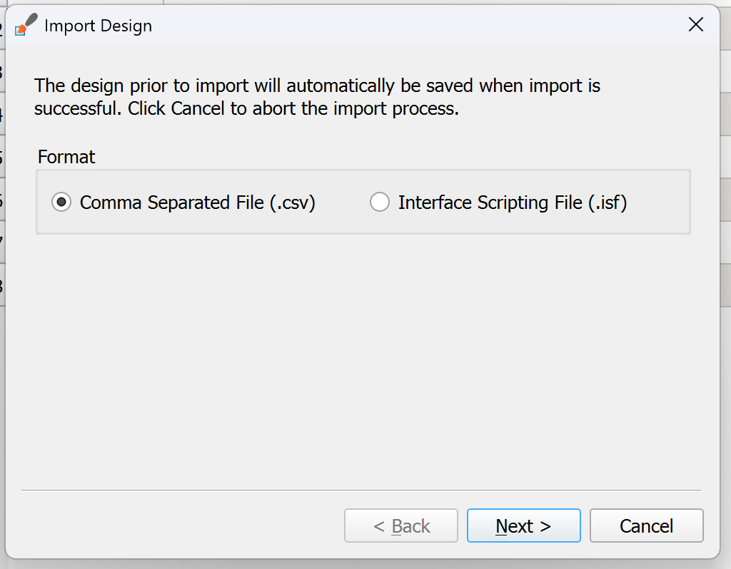
- Select "Comma Separated File (.csv)"
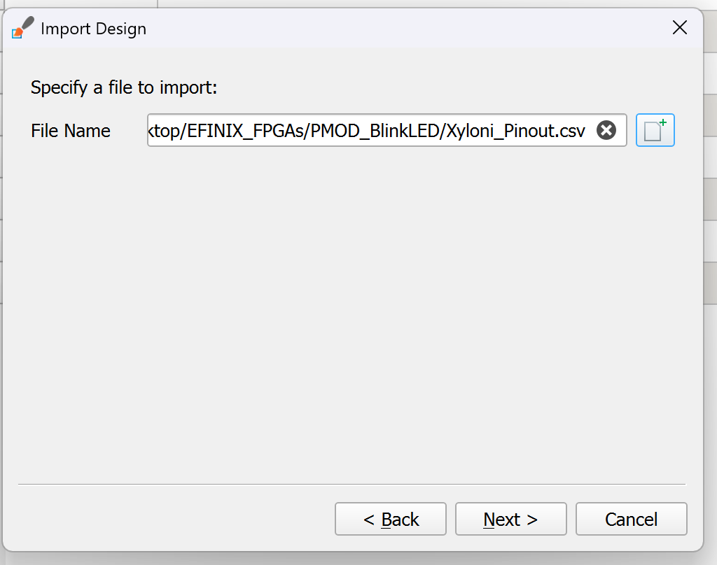
- Point to the "Xyloni_Pinout.csv" file
-
Press "Next" and "Finish"
-
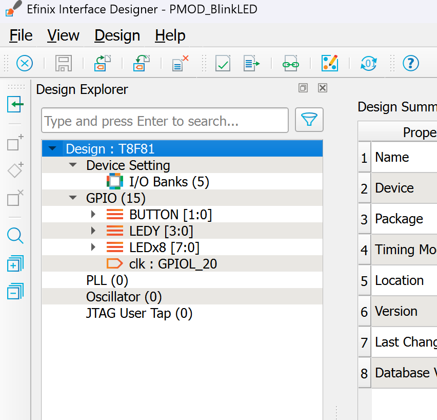
All pins for this project should be imported accordingly with the correct names that match the main module header.
Synthesis
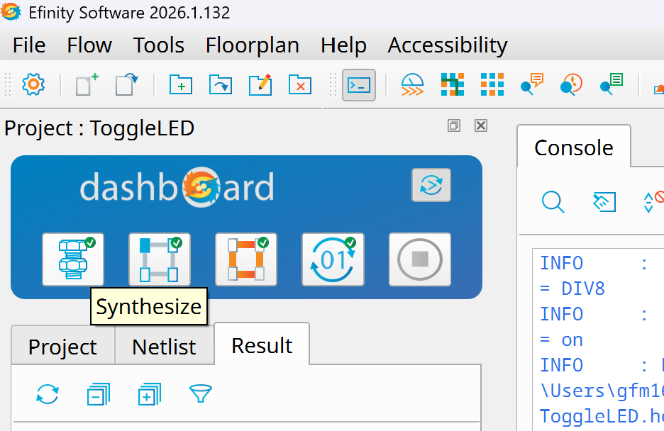
- On the dashboard press the button "Synthesize"
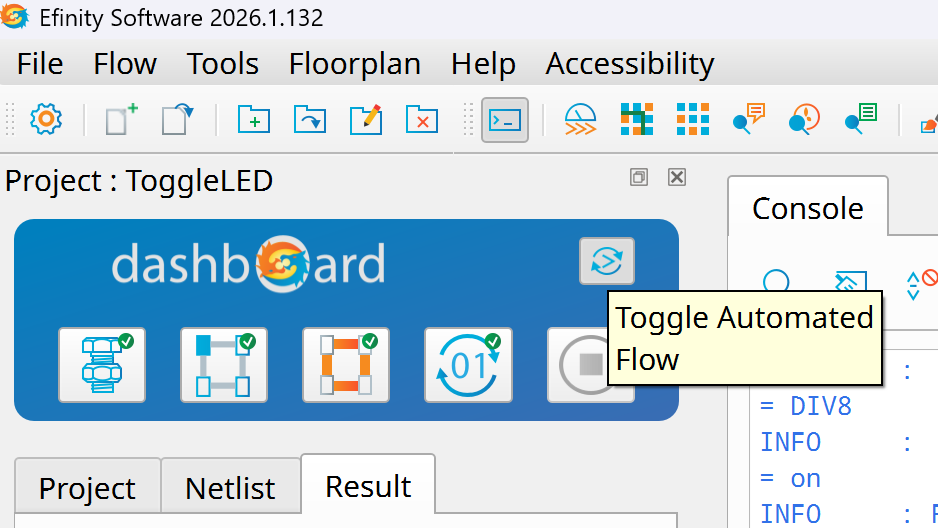
- If the button "Toggle Automated Flow" is enable, the rest of the sequence (Place --> Route --> Generate Bitstream) will happen automatically.
Download to Device
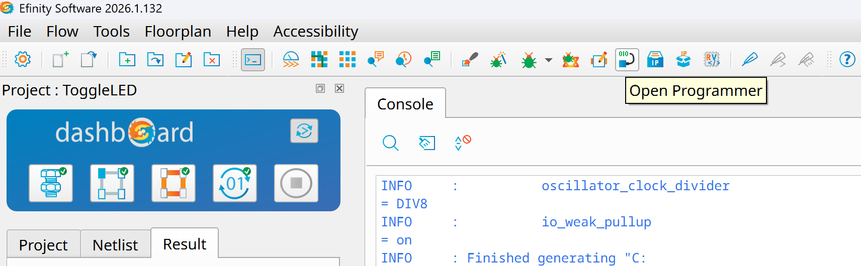
- Make sure Xyloni is connected to your computer and press the "Open Programmer" button
-
The programmer will detect your board automatically and it will select the .hex file to be sent to the board
-
Press "Start Program"
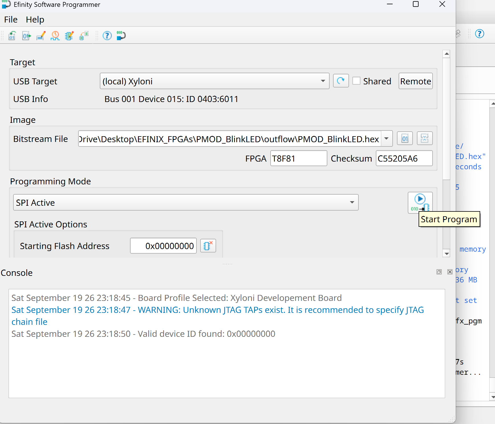
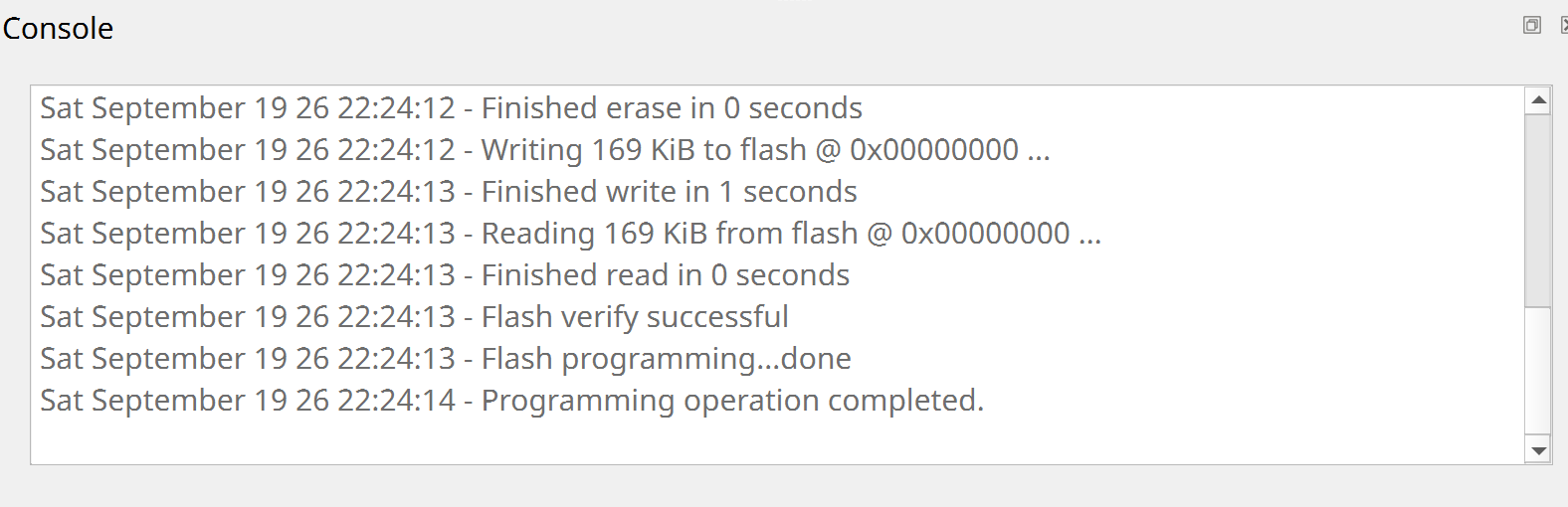
- Wait until programming operation is completed
- Press the button to toggle the LED
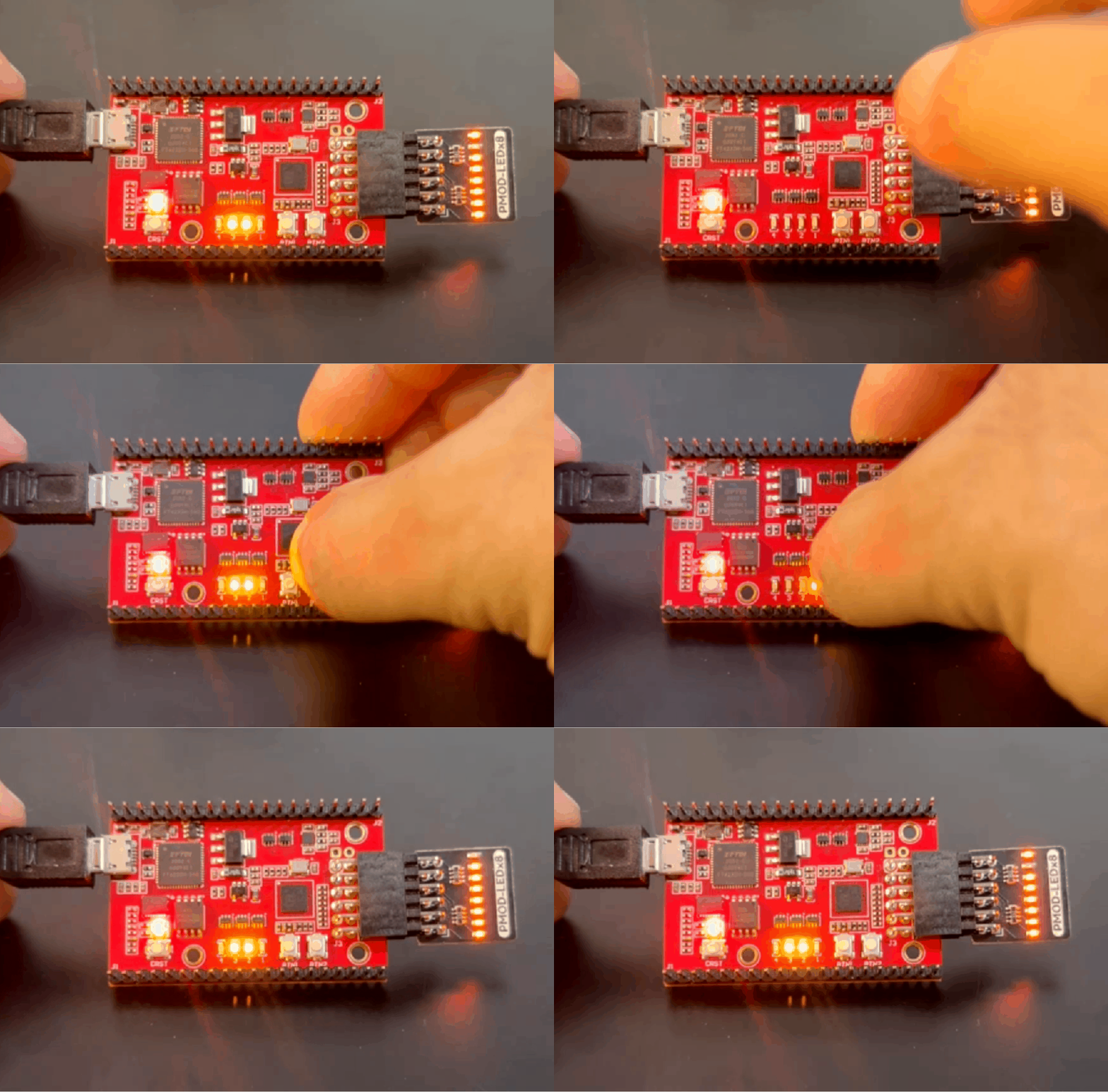
- You can use other PMODs as long as Vcc and GND pins on the PMOD are aligned correctly.
- In the case below, the LEDs of that PMOD are connected differently which generates a different pattern with the same synthesized hardware.