How to Create an Icon
Creating icons from schematics in Electric can be a valuable way to visually organize your designs as they grow more complex. Icons also help abstract circuit functionality, making it easier to understand your overall project.
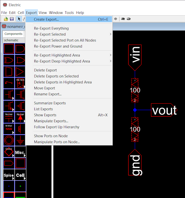
Export Input and Output Variables
Let's go over a simple circuit, a voltage divider, and create the icon for the schematic below. The inputs and outputs of your schematic should be exported with the create export command. In this case, I created a $Vin$, $Vout$ and $gnd$ using the create export command. You can apply this command to a wire, Wire-Pin or an Off-Page component.
Create Icon
With your schematic selected, go to "View -> Make Icon View"
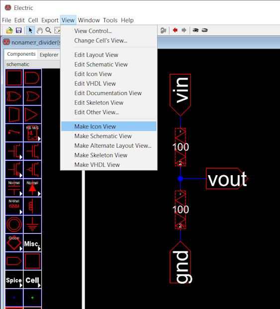
Electric will create a random icon with all the inputs and outputs that were exported and it will add a .ic file under the Explorer tab.
Edit Icon
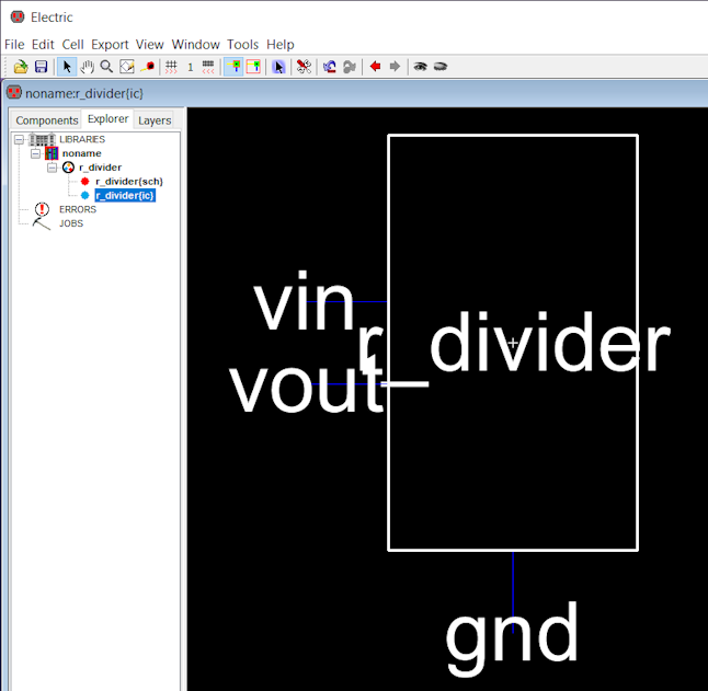
To edit the icon, go to the Explorer tab and double click on the .ic file.
You can now use the Components tab to design/modify the icon to your taste. If you want to create icons that are not predefined shapes, you need a little bit more patience and reuse and modify some of default components to achieve the desired shape.
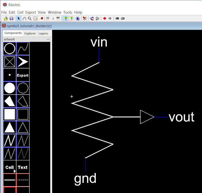
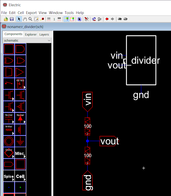
The icon on the schematic gets updated automatically.
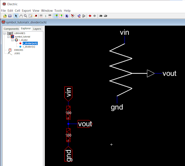
Use Icon
To use the new icon, create a new schematic and drag the icon as many as times as you want to your new design.
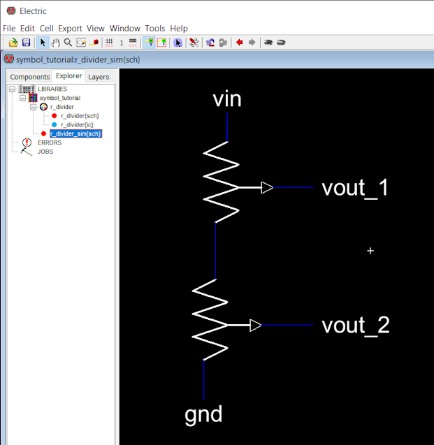
Simulate Icon
You can use spice commands to simulate the circuit and validate if the icon was successfully created.
![]()
![]()
References
- "Example on how to create a symbol" (5:16) [YouTube Video]