Blink LED
Step 1 - Create BlinkLED Project
Create a new project using Quartus called BlinkLED with a main.v file as the top module.
Note
If you don't remember how to do this, follow the "Toggle LED" article
Step 2 - Preliminary Design
In microcontrollers, LED blinking is typically implemented using delays, which rely on timers composed of counters. These timers are configured through a Hardware Abstraction Layer (HAL) code, which sets the appropriate registers to interact with the counters. The counters themselves are built into and provided by the microcontroller’s architecture.
In contrast, FPGAs do not provide built-in structures such as counters by default. Instead, they offer a blank canvas that designers must configure to meet their requirements.
I always recommend designing a block diagram that outlines the required hardware for your project. In this case is simple, we need a counter and an LED.
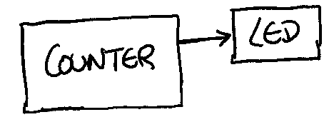
We will redesign the block diagram as we get more information about the project.
Step 3 - Design Option 1
Simulate
For digital logic, I like using Logisim (or Logisim Evolution) to simulate the initial design and gain a clearer visual understanding of the design idea. It might be a bit overkilled for this project, but developing good habits can help with more complex projects.
As stated before, the solution relies on using a counter. Counters need a clock source and FPGAs typically have a clock source available for use.
This particular board has an external oscillator at 24MHz that goes through a clock generator that provides one 10MHz clock for the on board ADC and two additional 50MHz clock for I/Os.
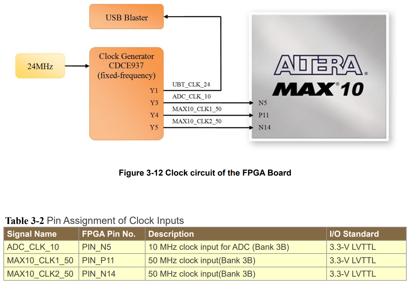
It is clear that feeding 50MHz (20ns) directly to a counter, will blink the LED super fast. We need to find a way to slow down this clock.
We can start by using a multi-bit counter that increments at a 20 ns rate and then connect a LED to the most significant bit (MSB) as illustrated below.
Let's try to write some HDL code to blink the LED at 1Hz (1 second).
Code Template
There are several ways to design counters in HDL, and they can include different features such as:
- Synchronous or Asynchronous
- Up count
- Down count
- Up/Down count
- Load
- Reset
- Enable
The HDL code will change depending on which features you want your counter to have. For now, we will keep things simple and use a basic up counter with a reset as our template.
Note
I will be using Verilog as the HDL language.
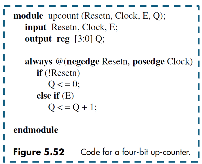
Verilog
I could write the counter as a separate submodule and then call it in the main.v file, but to keep things simple, I will just write the counter code directly inside the main module. I need to do some adjustment in order to connect the I/Os from the main module to the counter template.
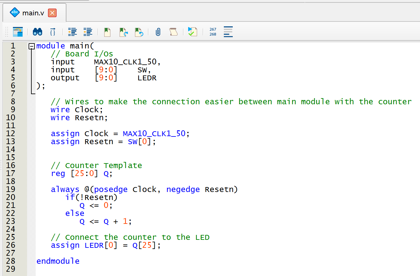
Let's do a bit of math to figure out what rate is the LED blinking with this code.
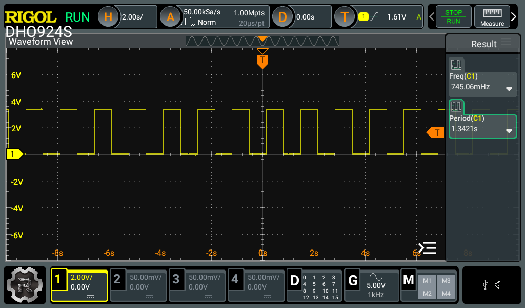
A 26-bit counter can count up to $2^{26} - 1 = 67,108,863$. But since LEDR[0] only toggles when the most significant bit (MSB), Q[25], changes, the effective count is $2^{25} + 1 = 33,554,433$. With the counter clock running at 20 ns, this gives an LED on time of about 0.67 seconds and an off time of another 0.67 seconds, for a total blink period of 1.34 seconds.
We can confirm this timing by connecting an oscilloscope to the LED.
As you are probably already thinking, we are very limited on the values that we can count by connecting the LED to any of the counter output pins. We need find another strategy to count to any value that we want.
Step 4 - Design Option 2
Redesign Block Diagram
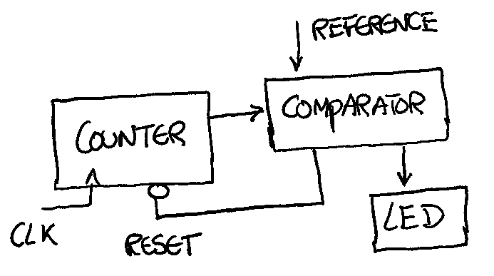
Looking back at the block diagram, we can include more details - such as the clock and reset pins - and also add a comparator. The comparator will monitor the counter’s value and reset it whenever it matches the reference number.
Simulate
In the simulation, we notice that the comparator’s output doesn’t stay high long enough - in fact, it resets so quickly that the LED never even blinks. To fix this, we need a way to hold (or latch) the value so the LED can actually blink. We achieve this by placing a memory element between the comparator and the LED.
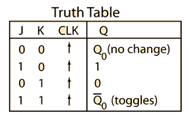
J-K flip-flops work well as memory elements. As you can see in the truth table (Link) , when both inputs J and K are set to 1, the output toggles each time the clock transitions high.
Verilog
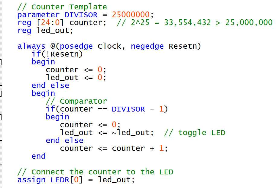
Adding a comparator and a memory element to the Verilog code is a little different from what we did earlier. I updated only the counter template section (the rest of the code stays the same) to match the block diagram names and included the code for the comparator, the LED toggle, and the counter reset.
Note
There is more behind the always statement that should be covered in a separate article. For now
Results were confirmed using an oscilloscope.


References
- DE10-Lite Official Website Documentation
- DE10-Lite Online Manual
- DE10_pin_assignments.qsf download
- Logisim Evolution Simulation (GitHub)
- BlinkLED Quartus Project (GitHub)