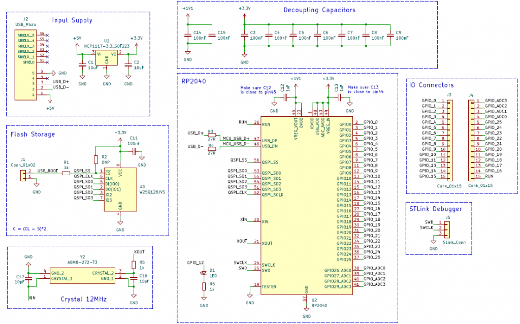
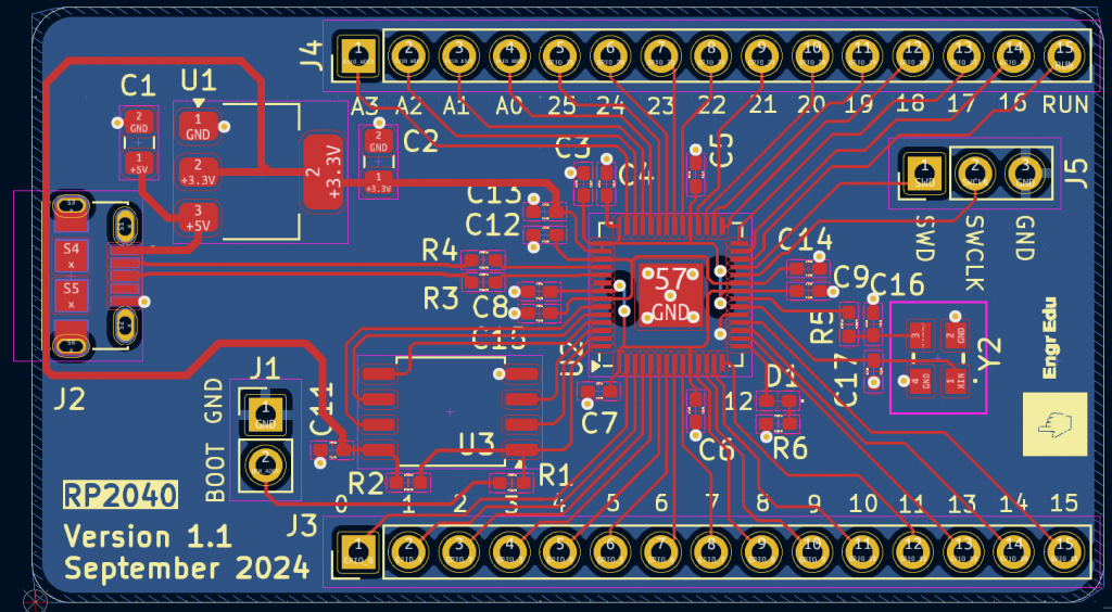
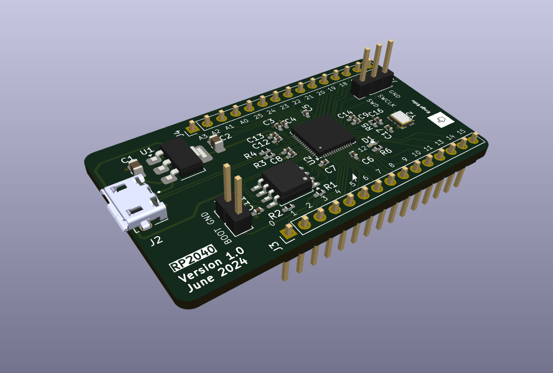
RP2040
RP2040
✔️ Introduction
The goal with this project is simple, get familiar with making a PCB board for the RP2040 chipset and test out PCBWay assembly service.
There are plenty of resources online to follow, but the nature of this project makes it hard to design or prototype it.
With that, the article jumps right away to the PCB design phase.

✔️ Assemble Stage
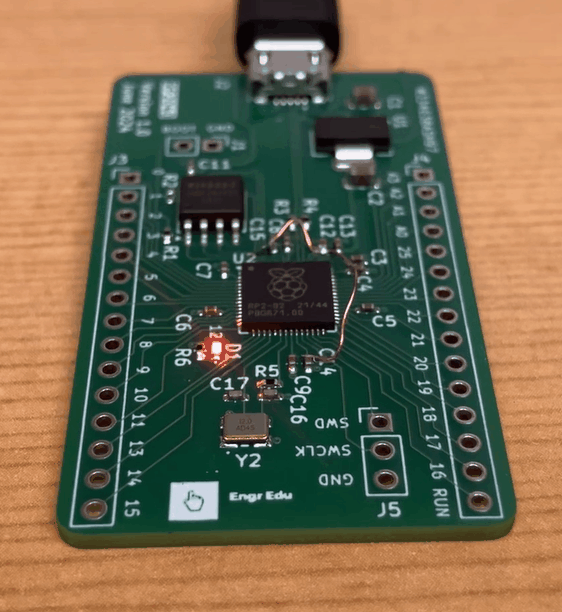
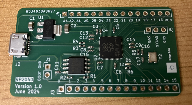
The boards were manufactured and assembled by PCBWay. As always a wonderful job.
One of the things that I love the most about the assembly service with PCBWay, is the constant communication throughout the entire process to make sure that all goes smoothly. For example, after providing the list of components needed, PCBWay answered back confirming that they had all the components requested. If files are missing, they communicate that information over email and they answer in a timely manner. During the assembly process, they reached to confirm if all components were soldered in the correct position. At last, when the board is ready to be shipped, I get a notification that the board is on the way.
Assembling a board is definitely a time consuming task. However, this professional behavior and prompt communication by PCBWay, gives me confidence to use the assembly service in future projects with critical timings.
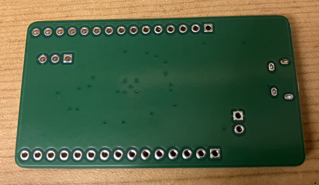
Unfortunately, I made a mistake during the routing phase and for some odd reason the +1V1 pins were not routed. I don’t know how I missed the DRC error during the PCB revision before generating the Gerber files.
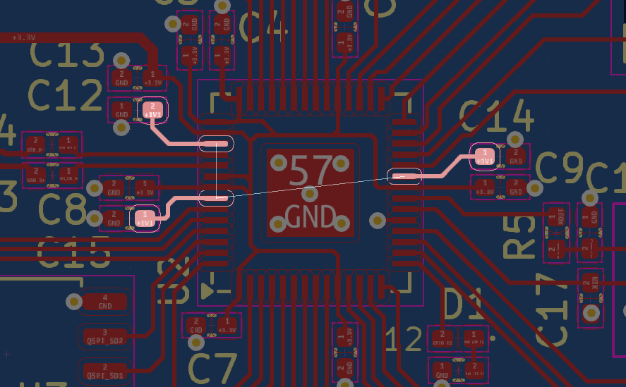
This issue was fixed by soldering some wires around.
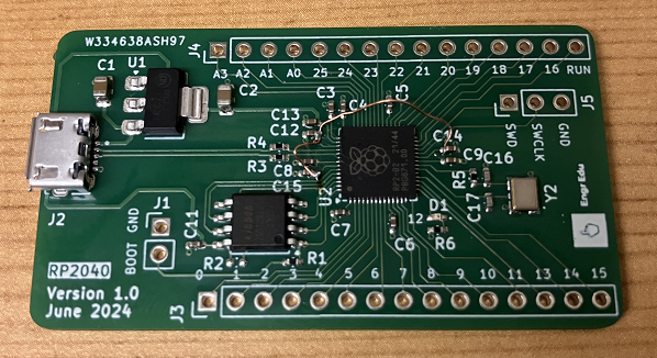
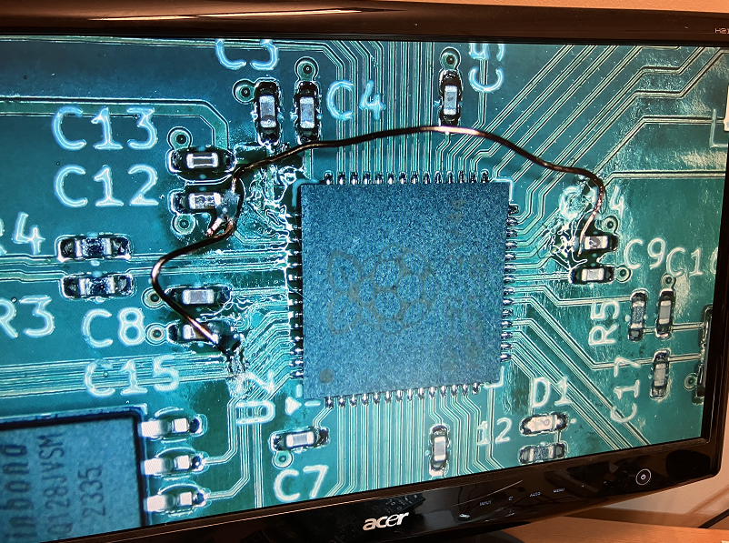
Schematic and layout were fixed and all files under the GitHub repository have this issue fixed.
✔️ Testing Stage
To program the RP2040 board, I follow this article that explains how to program the Raspberry Pi Pico using the Arduino IDE.
The code below shows an example how to use timer interrupt routines and blink LEDs at different speeds. GPIO pin 12 connects to the on board LED and GPIO pin 1 is available on the board pinout.
#include "hardware/irq.h"
#include "hardware/timer.h"
#include "pico/stdlib.h"

#define GPIO_1  1
#define GPIO_12 12

volatile bool ledState_1 = false;
volatile bool ledState_2 = false;

// Initialize Timers
struct repeating_timer timer1;
struct repeating_timer timer2;

// Timer ISR for the first timer
bool onTimer1(struct repeating_timer *t) {
  ledState_1 = !ledState_1; // Toggle the state
  digitalWrite(GPIO_1, ledState_1);
  return true;  // keep repeating
}

// Timer ISR for the second timer
bool onTimer2(struct repeating_timer *t) {
  ledState_2 = !ledState_2; // Toggle the state
  digitalWrite(GPIO_12, ledState_2);
  return true; // keep repeating
}

void setup() {
  // Initialize LEDS
  pinMode(GPIO_1, OUTPUT);
  pinMode(GPIO_12, OUTPUT);

  // Set up the first timer to fire every 100ms
  add_repeating_timer_ms(100, onTimer1, NULL, &timer1);

  // Set up the first timer to fire every 500ms
  add_repeating_timer_ms(100, onTimer2, NULL, &timer2);
}

void loop() {
  // empty loop as the work is done in the setup
}
Work in progress…
Since the RP2040 is a 32-bit dual ARM Cortex-M0+ microcontroller, I made the ST-Link pins available so I could use the STM32Cube IDE to program the chip.
I will update this section once I have this part tested and running properly.
✔️ GitHub Repository
KiCad Files
✔️ References
- [Ref 1] “Hardware design with RP2040”, Raspberry Pi Datasheets
- [Ref 2] “Raspberry Pi RP2040 Hardware Design | Altium Designer | JLCPCB – Phil’s Lab #28”, Phil’s Lab YouTube Channel [Video]
- [Ref 3] “A Designer’s Take on Raspberry Pi’s First Microcontroller”, All About Circuits [Article]
- [Ref 4] “Programming the Raspberry Pi Pico with Arduino”, BC Robotics [Article]
Sponsor