ADC – ADS8689 Interface
ADS8689 Interface
✔️ Introduction
Standard microcontrollers are generally not equipped to handle input voltages to their internal ADCs that exceed the microcontroller's supply voltage. The absolute maximum input rating for an ADC is typically linked to the microcontroller's supply voltage (VDDA).
This issue could be addressed by adding external resistors before the ADC to extend the input ranges. However, this approach introduces challenges such as gain error and gain drift.
To address this, one possible solution is to explore integrating external ADCs with the microcontroller. Some external ADCs support software-configurable input ranges (e.g., 0V to 5V, ±5V, and ±10V), though this comes at the cost of using digital communication protocols, such as SPI or I2C, to interface with the ADC.
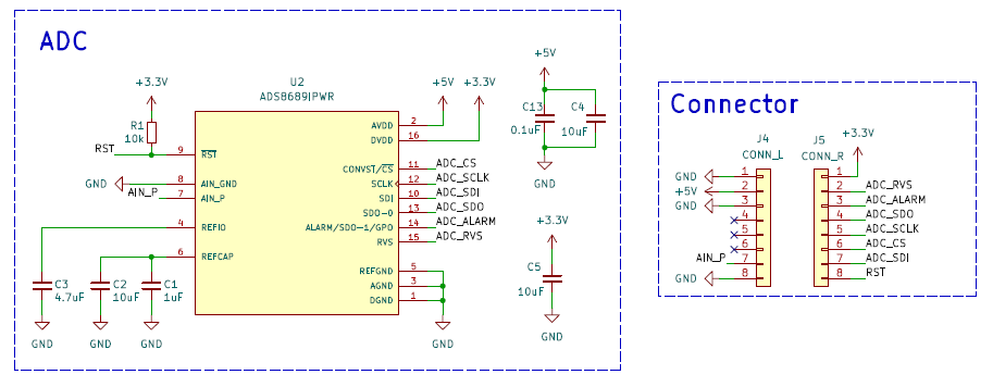
This article explore the ADS8689 from Texas Instruments.

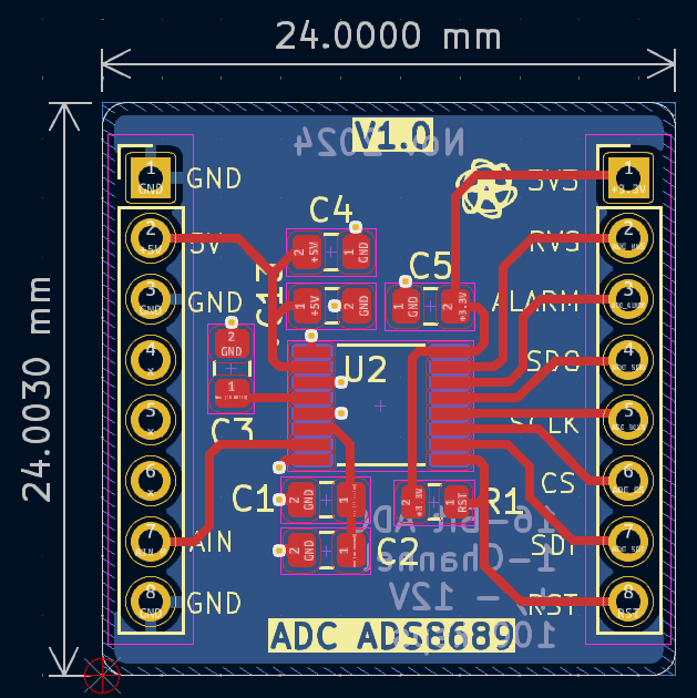
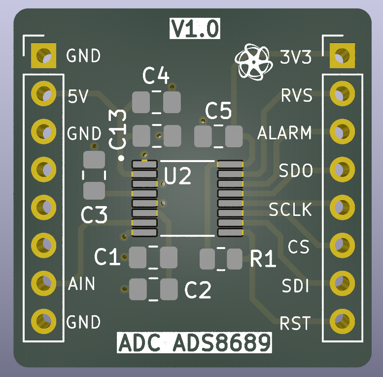
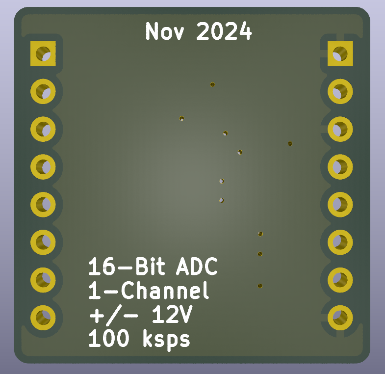
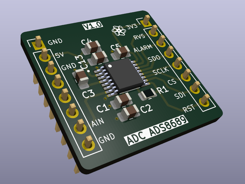
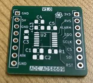
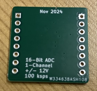
I developed a simple PCB board that allows testing the ADS8689 with different types of microcontrollers.
✔️ Assemble Stage
✔️ Arduino Uno Test
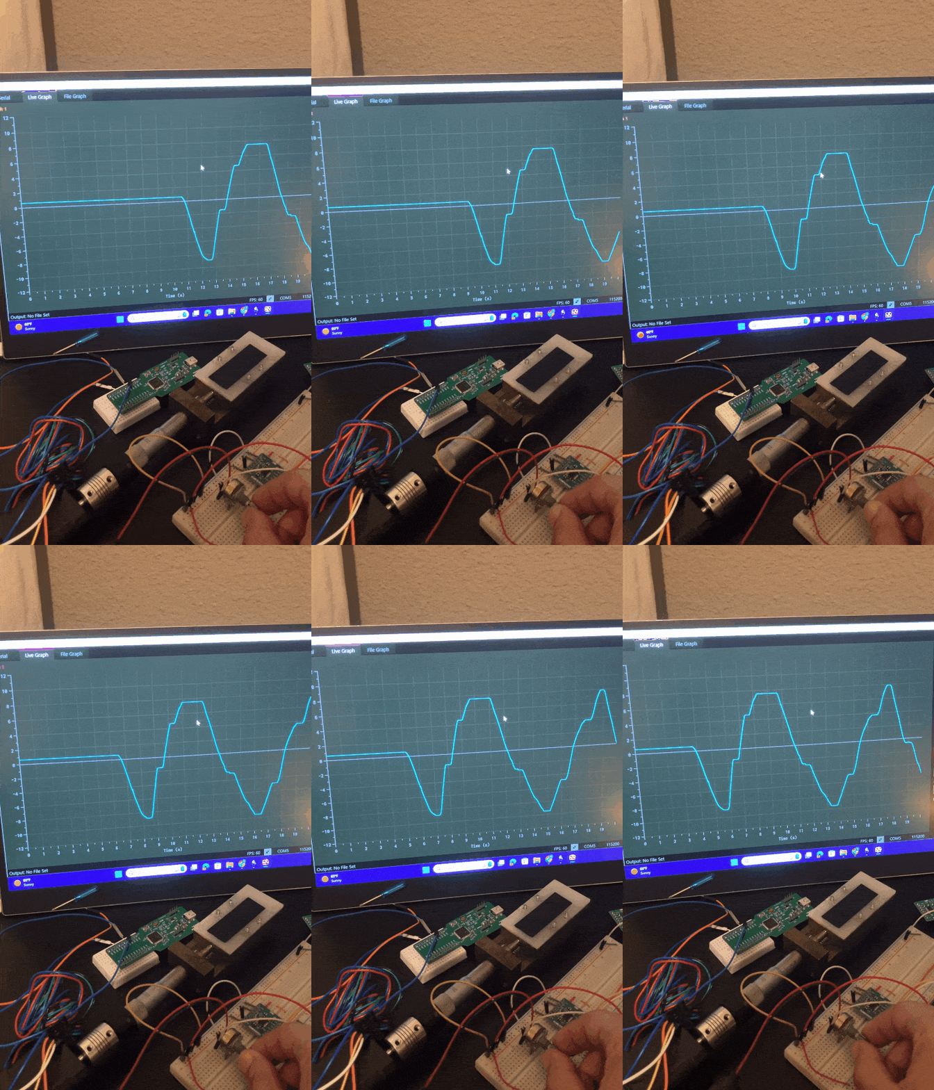
I kept the driver code simple and wrote a basic program to read the ADC values within the range of ±12V, send the data over UART, and plot the results using the Processing Grapher Program (Link)
#include "ADS8689.h"

/* ******************************
// Global Variables
****************************** */
uint16_t gADC_Data = 0;
float gADC_Voltage = 0.0;

void setup() {
  uint16_t answer = 0;

  // Init User Pins
  pinMode(CS_PIN, OUTPUT);
  digitalWrite(CS_PIN, HIGH);

  // Start Serial
  Serial.begin(115200);

  // Start SPI
  SPI.begin();

  // ADS8689_DEVICE_ID_REG
  answer = ADS8689_SendCommand(ADS8689_READ_HWORD_CMD, ADS8689_DEVICE_ID_REG, 0x0000);
  Serial.print("Device ID: ");
  Serial.println(answer);

  // ADS8689_RANGE_SEL_REG
  answer = ADS8689_SendCommand(ADS8689_READ_HWORD_CMD, ADS8689_RANGE_SEL_REG, 0x0000);
  Serial.print("RANGE_SEL_REG: ");
  Serial.println(answer);

  // INTREF_DIS[6] = 0b = Internal Reference is enabled -- RANGE_SEL[3:0] = 0000b = +/- 3xVref
  ADS8689_SendCommand(ADS8689_WRITE_CMD, ADS8689_RANGE_SEL_REG, 0b0000000000000000);
  // INTREF_DIS[6] = 0b = Internal Reference is enabled -- RANGE_SEL[3:0] = 1000b = 3xVref
  //ADS8689_SendCommand(ADS8689_WRITE_CMD, ADS8689_RANGE_SEL_REG, 0b0000000000001000);
}

void loop() {

  gADC_Data = ADS8689_SendCommand(ADS8689_NOP_CMD, ADS8689_NO_OP_REG, 0x0000);
  //Serial.println(gADC_Data);

  gADC_Voltage = (gADC_Data - 32768) * (24.576/65536); // RANGE_SEL[3:0] = 0000b = +/- 3xVref
  //gADC_Voltage = (gADC_Data) * (12.288/65536);  // RANGE_SEL[3:0] = 1000b = 3xVref

  Serial.println(gADC_Voltage);

  delay(1);  // 1ms
}
Since I don't have a power supply with me, I connected two 9V batteries to a potentiometer to create +/-9V and linked it to the ADC for testing.

✔️ GitHub Repository
✔️ References
- [REF 1] "Extending Input Voltage Range and Understanding Associated Errors for ADC with Integrated Front End", Texas Instruments [Article]
Sponsor

