Simple Examples
Let's use a couple of simple examples to illustrate the process of synthesizing and deploying the code into a board in Logisim Evolution.
Example 1
Step 1 - Design
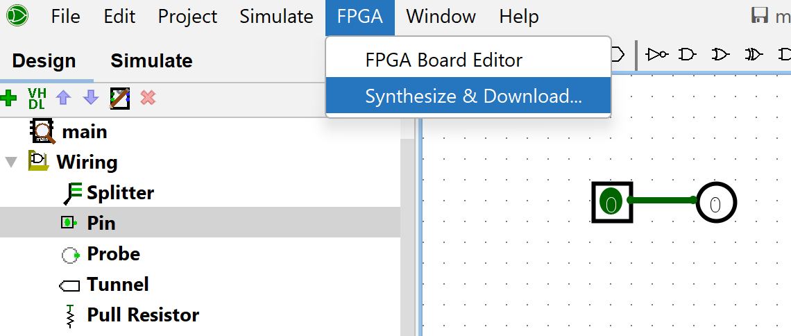
- Add 2 pins and set one of them as output and facing west. Connect them together with a wire.

Step 2 - Annotate
- Go to "FPGA->Synthesize & Download"
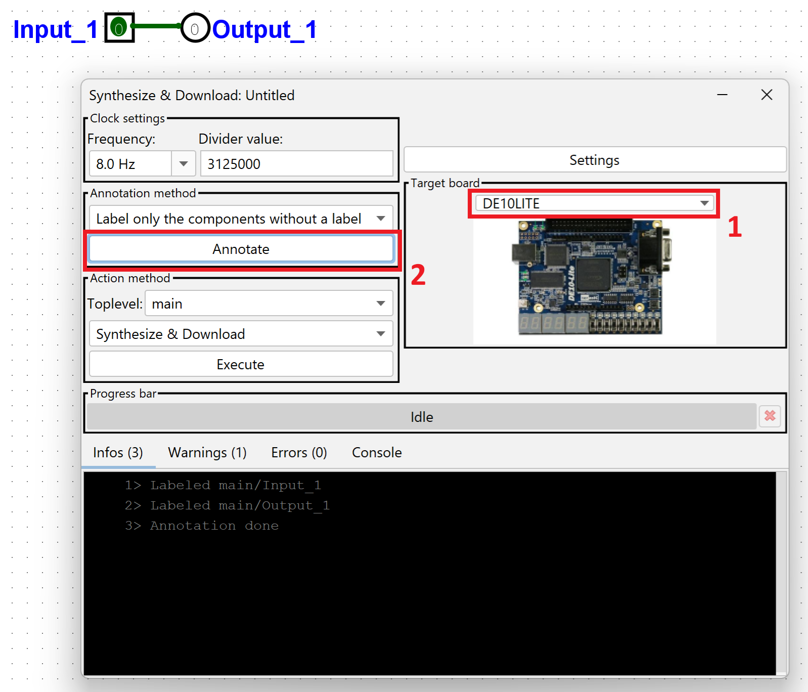
- Then select the target board: DE10LITE
- "Annotate" your schematic: annotate will give names to all inputs and outputs in the schematic
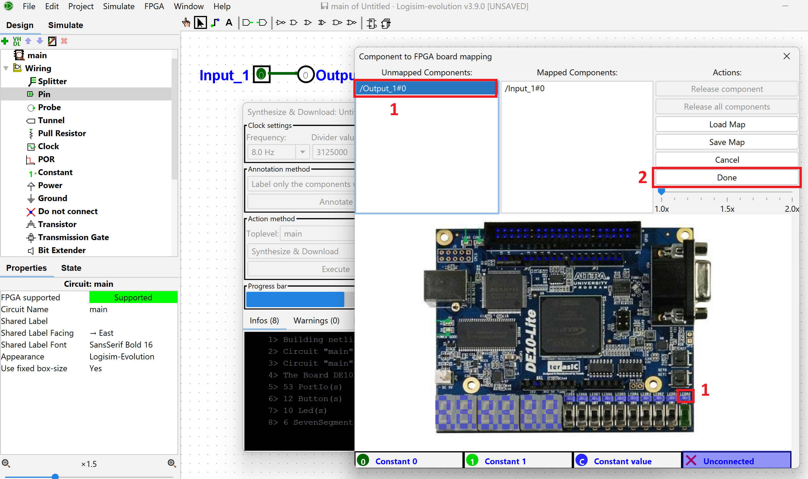
Step 3 - IOs Mapping and Synth
- Press the "Execute" button and the software will ask you to map the inputs and outputs to physical components on the board.
- As you keep mapping them, the board highlights the components in green.
- Once you are done, press the "Done" button.
- The software will start synthesizing your schematic.
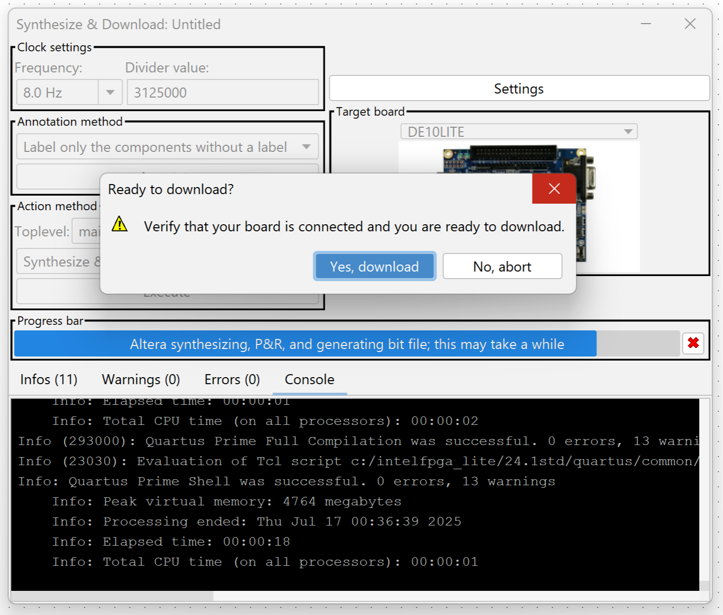
Step 4 - Download Program
- After synthesizing the schematic, the program will ask you if you are ready to download the program to the FPGA. Make sure that you have the board connected to the computer and press "Yes, download".
- Once the software is done programming it shows "Idle" on the progress bar.
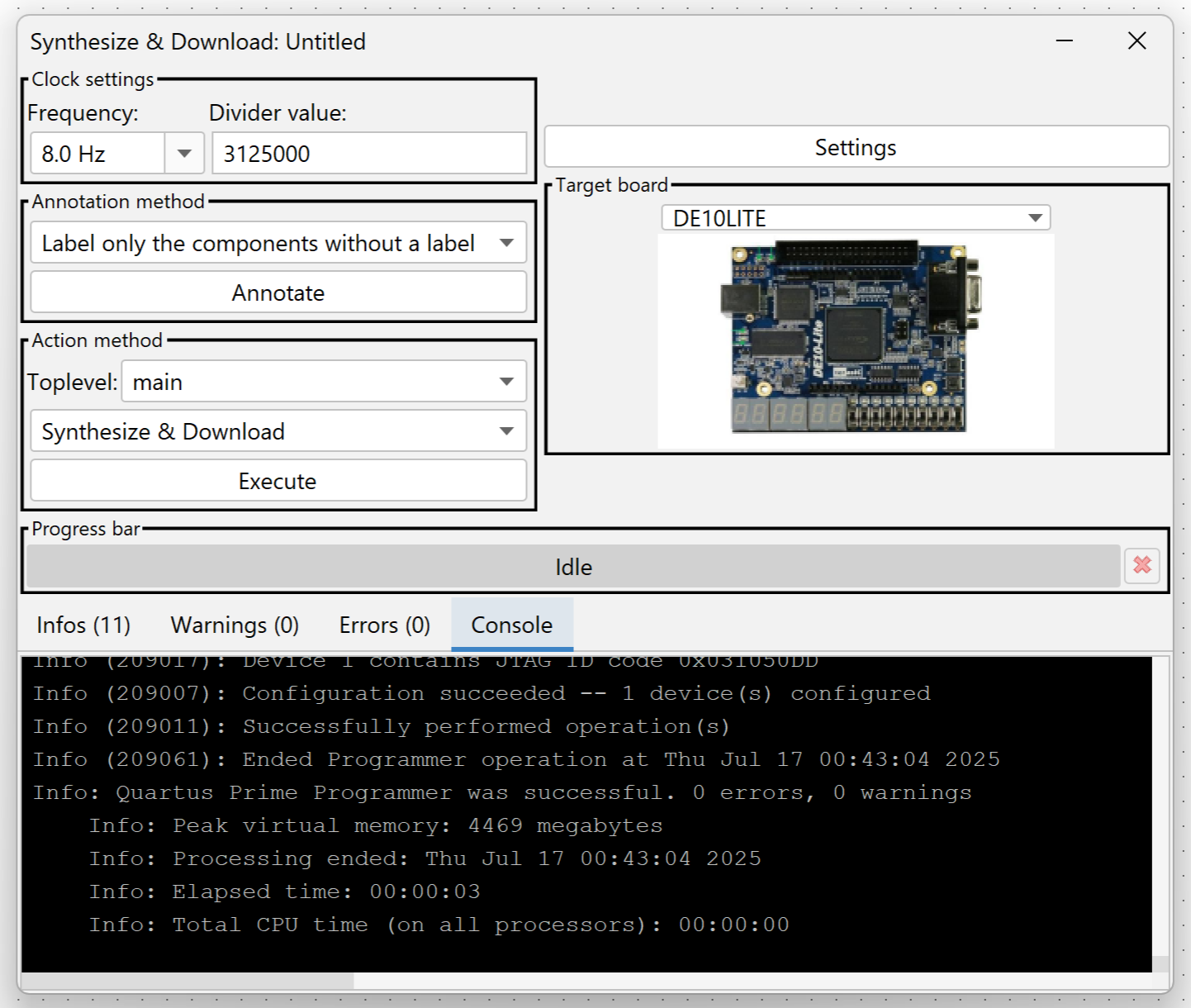
- You can now test your design
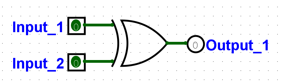
Example 2
See if you can build, deploy and test the following schematic: