Chapter 1.2 Voltage, Current and Resistance
Exercise 1.1
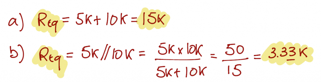
For this exercise we can use the equivalent resistance equations from page 5.
\[ R = R_1 + R_2 \;\;\; \text{(Eq. 1.3)} \]
\[ R = \frac{R_1 R_2}{R_1 + R_2} \;\;\; \text{(Eq. 1.4)} \]
Exercise 1.2
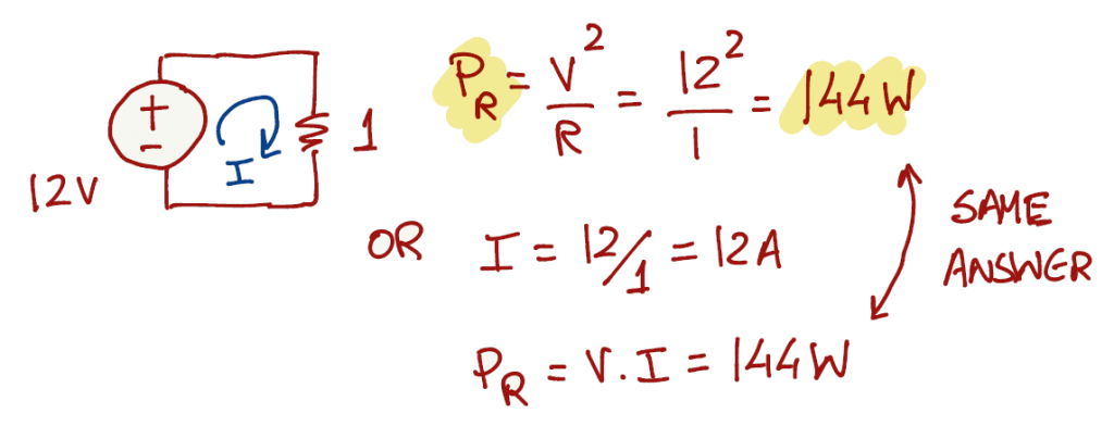
On page 6, section C, you can find the equation of power dissipation by a resistor and respective equivalent forms. When questions are descriptive and don't provide a schematic, it helps if we design the respective schematic in order to understand which tool(s) can be use to solve the exercise.
- Option 1: since the voltage source is in parallel with the resistor, the resistor sees the same voltage (12V).
- Option 2: apply ohm's law and get the current in the circuit and then apply the power equation.
Exercise 1.3
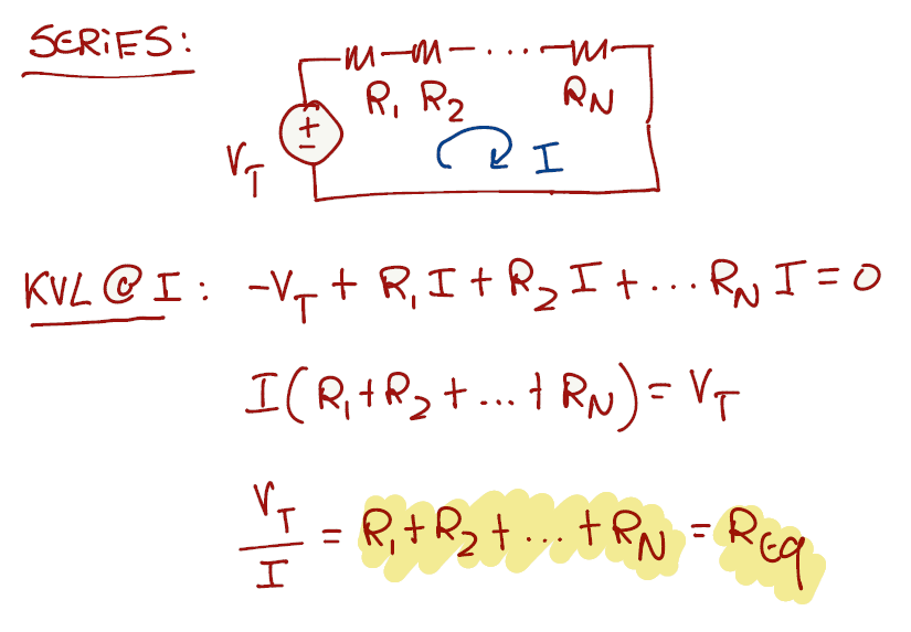
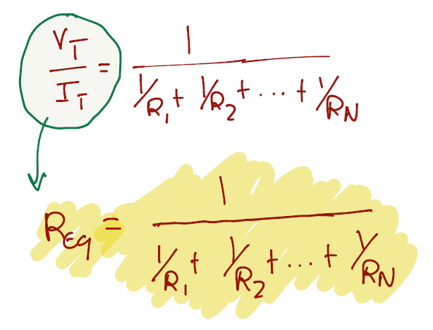
To prove the formula for series, we can use KVL around a loop of components in series and apply ohm's law on the final equation to get the equivalent resistance.
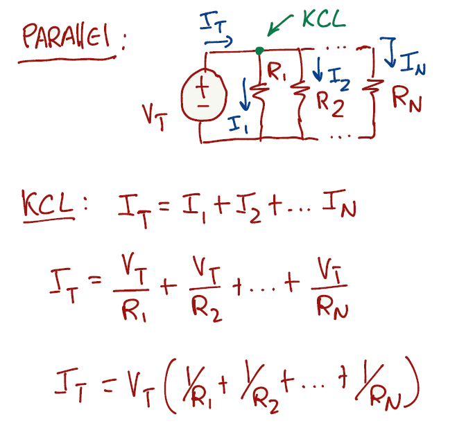
To prove the formula for parallel, we can use KCL on a node and apply ohm's law on the equation to get the equivalent resistance.
Exercise 1.4
Is proven in Exercise 1.3
Exercise 1.5
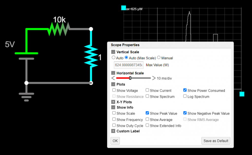
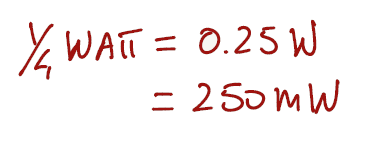
Let's start the exercise by expressing a quarter of a watt in mW.
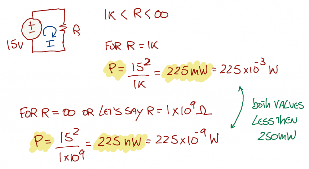
We need to evaluate the circuit for all R's greater than 1kΩ. For R = 1kΩ the power is 225 mW and for R = 1GΩ the power is 0.000225 mW. Both values are smaller than 250 mW.
Exercise 1.6
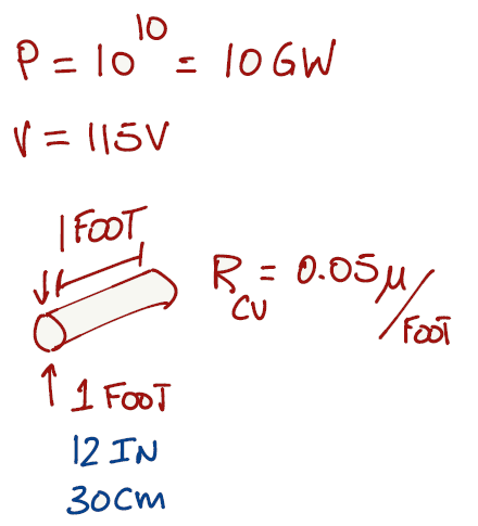
Some exercises benefit by writing down all the available information before tackling the solution. For this particular case, if you are not familiar with the imperial system (feet or inches), we can convert the answer to the metric system (meters, centimeters or millimeters).
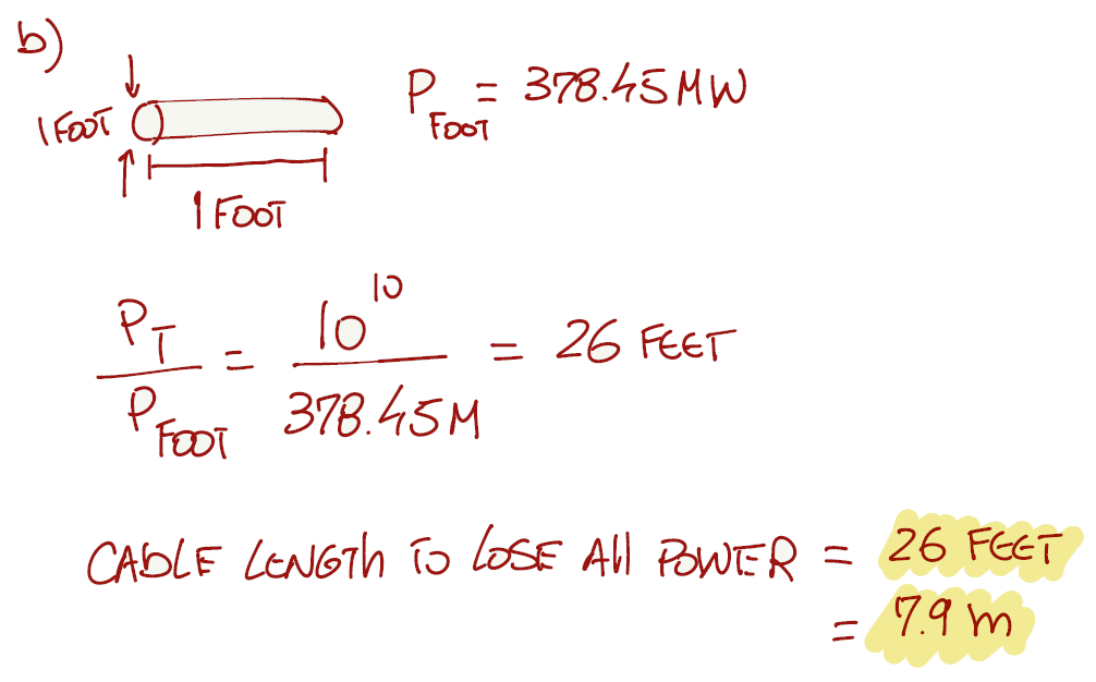
There are 4 different mechanism of transferring heat in an object: conduction, convection, radiation and vaporization (Link). Thermal radiation is energy transfer by the emission of electromagnetic waves which carry energy away from the emitting object. This is the case of the cable, and this thermal radiation generates heat.
The relationship governing the net radiation from hot objects is called the Stefan-Boltzmann law:
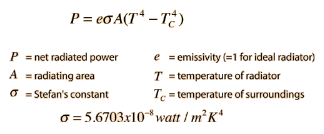
We can write the Stefan-Boltzmann law in terms of absolute temperature (T) instead of considering the hot object radiating energy to its cooler surroundings at temperature Tc. We can also consider an ideal radiator and set e = 1:
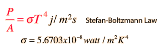
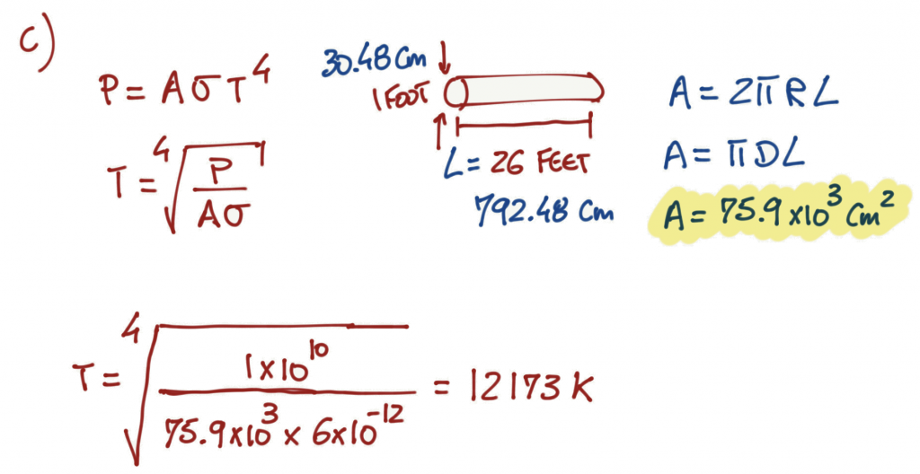
As a point of reference, the sun radiates at around 5800K and a hot campfire at 800K. The cable temperature for this example is indeed crazy.
To reduce the heat in a cable, we can apply two solutions:
Solution 1
- if we increase the voltage from 115V to 115kV, and since the power is the same, the current that flows in the wire is going to be less.
- If the current is less, the power lost per foot is going to be reduced significantly.
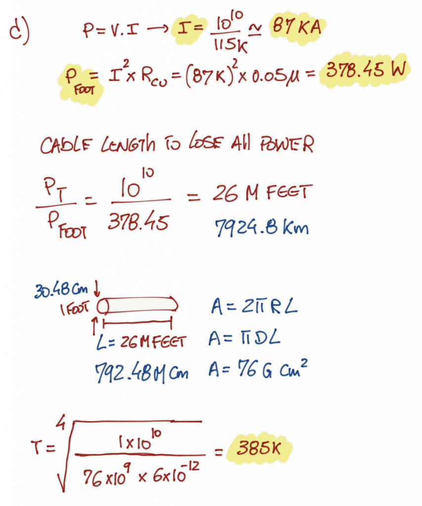
The cable length is now 1x10^6 times longer and the cable heat is reduced significantly. As a point of reference, the heat is now around 106 degrees Celsius (223 Fahrenheit).
Solutions 2
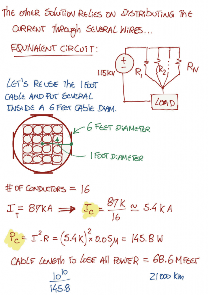
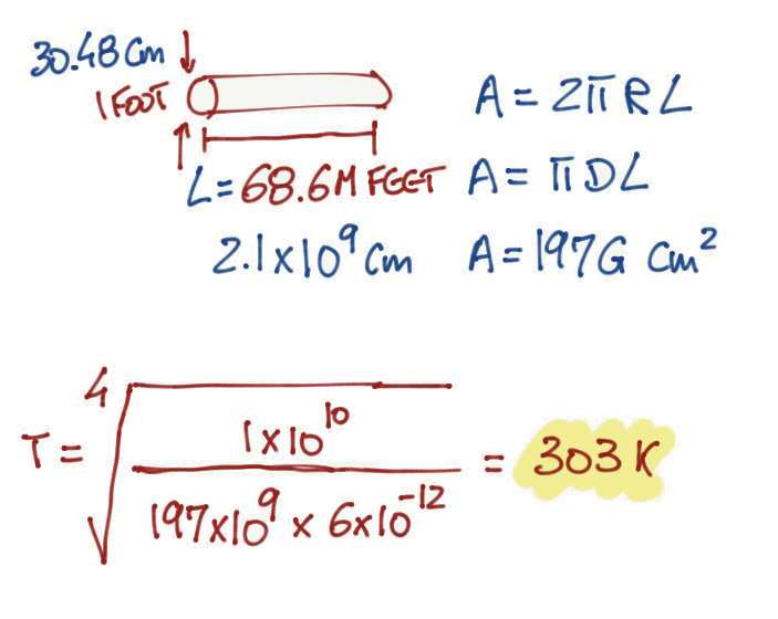
With this techniques, we reduce the temperature even more, close to 29 degrees Celsius (84 Fahrenheit).
Exercise 1.7
Remember that designing a schematic can help visualize the problem that your are trying to solve.
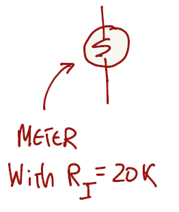
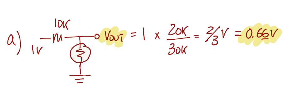
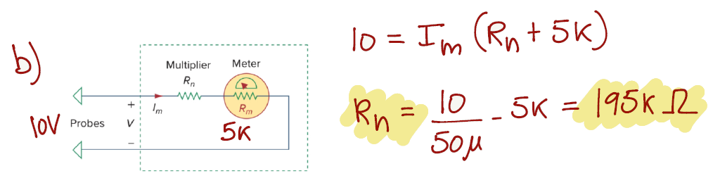
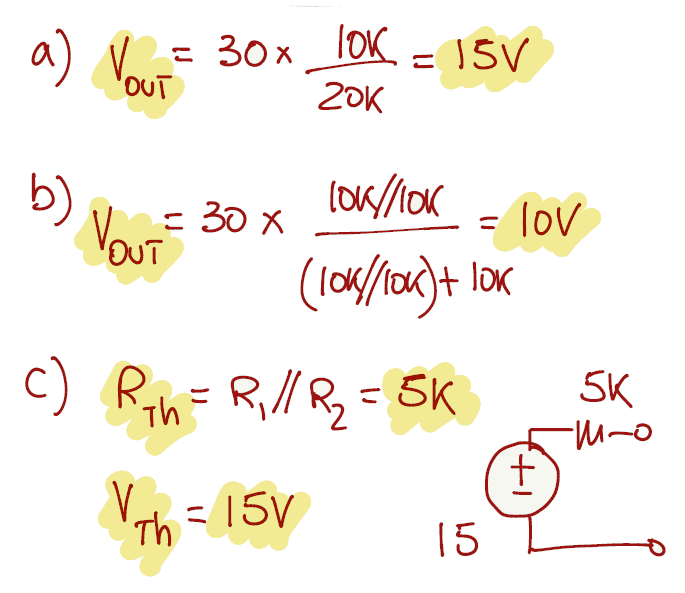
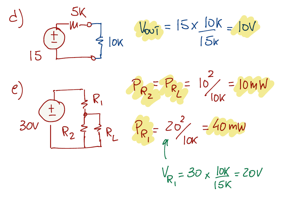
For the first question the voltage source as an internal resistance of 10kΩ and it is connected in series with the meter. Since all the components are connected in series, we can apply the voltage divider equation (from page 7).
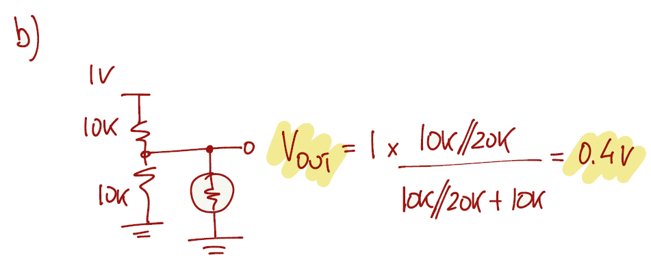
The voltage divider can still be used to answer b), however the resistor R2 from the voltage divider equation is now the parallel of 10kΩ with 20kΩ, changing the output voltage accordingly.
We have been solving the exercises with hand calculations but we can also simulate the circuits to get a better understanding of our solutions. There are a lot of different circuit simulators that you can use. Falstad is free and does a wonderful job with the visualization of the current and voltages in your circuits, and we can also share the circuits by exporting a link.
Falstad link for this exercise.
Exercise 1.8
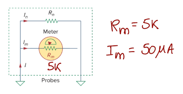
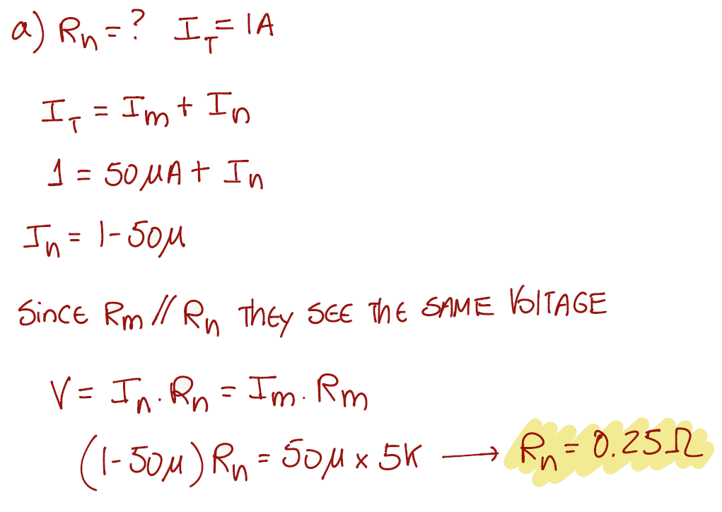
We will start by designing what the exercise is asking for:
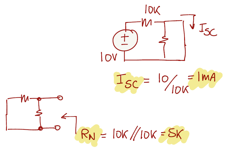
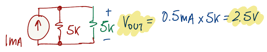
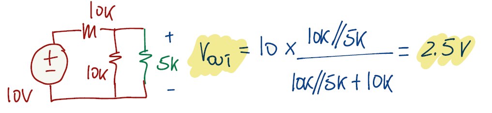
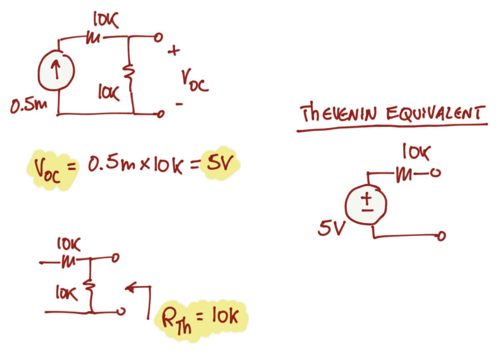
Exercise 1.9
This exercise can be a bit confusing at first, but let's design the schematic for a DMM in voltage mode (voltmeter). The Rn resistance will be ignored for this exercise because we don't need to have the voltmeter changing ranges. RL is representing the "leakage" resistance and Rm is the DMM internal resistance for the 2V dc range. The available dc source can go up to 10V.
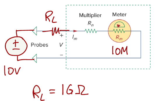
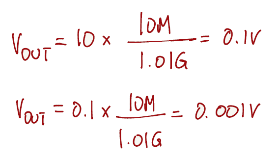
Since all elements in this circuit are connected in series, we can apply the voltage divider equation (from page 7) to get a reading from the DMM meter. If we vary the input voltage source from 0.1V to 10V we will be able to read values from 0.1V to 0.001v
\[ V_{out} = V_{in}*\frac{R_m}{R_m+R_L} \]
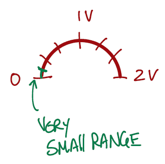
If the meter is analog, the needle will not move that much for that range of values.
However, the problem is asking a different question. The problem is asking how accurately can we measure a leakage resistance. To answer that question, we need to rewrite the voltage divider in terms of RL.
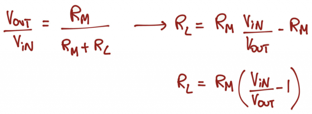
With the equation written in this form we have the DMM reading the value of RL, and we can control the range of values by varying the input dc voltage source accordingly.
Let's use Desmos to visualize this (Link). On the animation below, varying Vin represents changing the resolution of the reading, and varying Vout represents changing the output voltage reading in order to see what RL is connected in the circuit.
We can see that for Vin = 10V, we can measure RL's from 990GΩ to 40GΩ. For Vin = 2.1V, we can measure RL's from 200GΩ to 500kΩ. Vin shouldn't be less than Vout, otherwise you will get negative values of resistance.
Exercise 1.10
For this exercise we keep applying the voltage divider equation (from page 7).
Exercise 1.11
You can find the solution for this exercise in any classic circuits book. It relies on finding when the derivative of the power equation combined with the voltage divider equation is equal to zero with respect to RL.
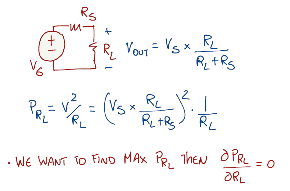
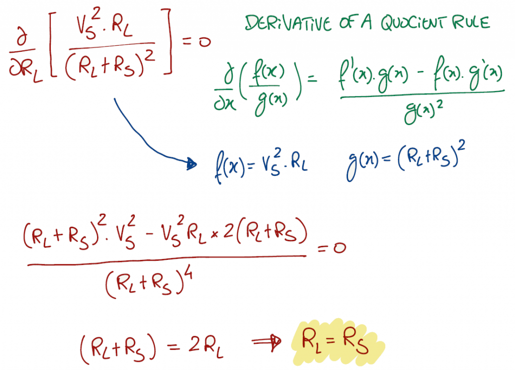
Let's plot the power equation on Desmos and analyze the answer (Link). Notice on the animation below, the power is maximum when RL = Rs no matter how you vary Rs. Varying Vs, the maximum power value changes (with no surprise) but it is still related to RL = Rs.
Falstad link for this exercise